Sony FST-GTK11iP Service Manual

Sony FST-GTK11iP Service Manual

Home audio docking system
Hide thumbs Also See for FST-GTK11iP:
Table of Contents

Advertisement

SERVICE MANUAL
Ver. 1.0 2012.03
AUDIO POWER SPECIFICATIONS
POWER OUTPUT AND TOTAL HARMONIC DISTORTION:
(The United States model only)
With 3.5 ohm loads, both channels driven, from 120
10,000 Hz; rated
50 watts per channel minimum RMS power, with no more than 0.7% total
harmonic distortion from 250 milliwatts to rated output.
Amplifier section (US model)
RMS output power (reference):
210 W + 210 W (per channel at 3.5 Ω, 1 kHz)
Amplifier section (Except US model)
The following are measured at AC 120 V
240 V, 50/60 Hz (Latin American
models (except for Mexican and Argentine models))
The following are measured at AC 127 V, 60 Hz (Mexican model)
The following are measured at AC 220 V
240 V, 50/60 Hz (European,
Russian, Australian and Argentine models)
The following are measured at AC 120 V
240 V, 50/60 Hz (Other models)
FST-GTK33iP/RDH-GTK33iP
Power output (rated):
100 W + 100 W (at 3.5 Ω, 1 kHz, 1% THD)
RMS output power (reference):
210 W + 210 W (per channel at 3.5 Ω, 1 kHz)
FST-GTK11iP/RDH-GTK11iP
Power output (rated):
55 W + 55 W (at 3 Ω, 1 kHz, 1% THD)
RMS output power (reference):
115 W + 115 W (per channel at 3 Ω, 1 kHz)
Speaker section
Speaker system: 2 way speaker system, Bass reflex
Speaker units:
FST-GTK33iP/RDH-GTK33iP:
Woofer: 200 mm, cone type
Tweeter: 66 mm, cone type
FST-GTK11iP/RDH-GTK11iP:
Woofer: 160 mm, cone type
Tweeter: 40 mm, cone type
Rated impedance:
FST-GTK33iP/RDH-GTK33iP: 3.5 Ω
FST-GTK11iP/RDH-GTK11iP: 3.0 Ω
Input
DVD/PC IN (audio in L/R):
FST-GTK33iP/RDH-GTK33iP: Sensitivity 1,000 mV, impedance 47 kΩ
FST-GTK11iP/RDH-GTK11iP: Sensitivity 1,500 mV, impedance 47 kΩ
9-893-451-01
Sony Corporation
2012C33-1
©
2012.03
Published by Sony Techno Create Corporation
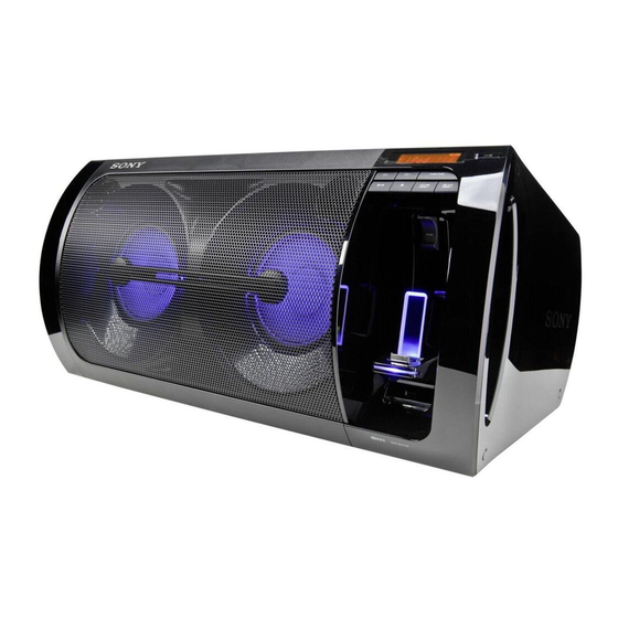
Photo: RDH-GTK33iP
SPECIFICATIONS
iPod/iPhone section
iPod/iPhone connector:
Output voltage: DC 5 V
Maximum output current: 1 A
Compatible iPod/iPhone models:
iPod touch 4th generation
iPod touch 3rd generation
iPod touch 2nd generation
iPod nano 6th generation
iPod nano 5th generation (video camera)
iPod nano 4th generation (video)
iPod nano 3rd generation (video)
iPod classic
iPhone 4S
iPhone 4
iPhone 3GS
iPhone 3G
"Made for iPod, " and "Made for iPhone" mean that an electronic accessory has
been designed to connect specifically to iPod or iPhone, respectively, and has
been certified by the developer to meet Apple performance standards. Apple
is not responsible for the operation of this device or its compliance with safety
and regulatory standards. Please note that the use of this accessory with iPod
or iPhone may affect wireless performance.
USB section
Supported bit rates:
MP3 (MPEG 1 Audio Layer-3): 32 kbps
320 kbps, VBR
WMA: 48 kbps
192 kbps, VBR
AAC: 48 kbps
320 kbps
Sampling frequencies:
MP3 (MPEG 1 Audio Layer-3): 32/44.1/48 kHz
WMA: 44.1 kHz
AAC: 44.1 kHz
(USB) port: Type A, maximum current 500 mA
FST-GTK11iP/GTK33iP/
RDH-GTK11iP/GTK33iP
Saudi Arabia Model
Tuner section
FM stereo, FM/AM superheterodyne tuner
Antenna:
FM lead antenna
AM loop antenna
FM tuner section:
Tuning range:
87.5 MHz
108.0 MHz (100 kHz step) (US model)
87.5 MHz
108.0 MHz (50 kHz step) (Except US model)
AM tuner section:
Tuning range:
European, Russian and Saudi Arabian models:
531 kHz
1,602 kHz (9 kHz step)
US and Latin American models:
530 kHz
1,710 kHz (10 kHz step)
531 kHz
1,710 kHz (9 kHz step)
Australian model:
531 kHz
1,710 kHz (9 kHz step)
530 kHz
1,710 kHz (10 kHz step)
Other models:
531 kHz
1,602 kHz (9 kHz step)
530 kHz
1,610 kHz (10 kHz step)
General
Power requirements:
US model:
AC 120 V, 60 Hz
Latin American models (except for Mexican and Argentine models):
AC
120 V
240 V, 50/60 Hz
Mexican model:
AC 127 V, 60 Hz
European, Russian, Australian and Argentine models:
AC 220 V
240 V, 50/60 Hz
Other models:
AC 120 V
240 V, 50/60 Hz
Power consumption:
FST-GTK33iP/RDH-GTK33iP: 75 W (0.5 W at the Power Saving mode)
FST-GTK11iP/RDH-GTK11iP: 45 W (0.5 W at the Power Saving mode)
Dimensions (W/H/D):
FST-GTK33iP/RDH-GTK33iP: Approx. 768.5 mm × 323 mm × 385 mm
FST-GTK11iP/RDH-GTK11iP: Approx. 678.5 mm × 323 mm × 385 mm
Mass:
FST-GTK33iP/RDH-GTK33iP: Approx. 14.0 kg
FST-GTK11iP/RDH-GTK11iP: Approx. 12.5 kg
Quantity of the unit: 1 piece
Supplied accessories: Remote Commander (1), R6 (Size AA) batteries (2),
FM lead/AM loop antenna (1)
Design and specifications are subject to change without notice.
HOME AUDIO DOCKING SYSTEM
US Model
RDH-GTK33iP
AEP Model
UK Model
Singapore Model
Malaysia Model
RDH-GTK11iP
E Model
FST-GTK11iP/GTK33iP
Australian Model
RDH-GTK11iP/GTK33iP
Chilean Model
Peruvian Model
FST-GTK33iP
License and Trademark Notice
iPhone, iPod, iPod classic, iPod nano, and iPod touch
are trademarks of Apple Inc., registered in the U.S. and
other countries.
MPEG Layer-3 audio coding technology and patents
licensed from Fraunhofer IIS and Thomson.
Windows Media is either a registered trademark or
trademark of Microsoft Corporation in the United
States and/or other countries.
This product contains technology subject to certain
intellectual property rights of Microsoft. Use or
distribution of this technology outside of this product
is prohibited without the appropriate license(s) from
Microsoft.
All other trademarks and registered trademarks are of
their respective holders. In this manual,
and
®
are not specified.
marks

Advertisement

Table of Contents
loading

Summary of Contents for Sony FST-GTK11iP

  • Page 1 Power consumption: Woofer: 160 mm, cone type FST-GTK33iP/RDH-GTK33iP: 75 W (0.5 W at the Power Saving mode) Tweeter: 40 mm, cone type FST-GTK11iP/RDH-GTK11iP: 45 W (0.5 W at the Power Saving mode) Rated impedance: Dimensions (W/H/D): FST-GTK33iP/RDH-GTK33iP: 3.5 Ω FST-GTK33iP/RDH-GTK33iP: Approx. 768.5 mm × 323 mm × 385 mm FST-GTK11iP/RDH-GTK11iP: 3.0 Ω...
  • Page 2: Leakage Test

    COMPONENTS IDENTIFIED BY MARK 0 OR DOTTED LINE WITH MARK 0 ON THE SCHEMATIC DIAGRAMS AND IN THE PARTS LIST ARE CRITICAL TO SAFE OPERATION. REPLACE THESE COMPONENTS WITH SONY PARTS WHOSE PART NUMBERS APPEAR AS SHOWN IN THIS MANUAL OR IN SUPPLEMENTS PUBLISHED BY SONY.
  • Page 3: Table Of Contents

    FST-GTK11iP/GTK33iP/RDH-GTK11iP/GTK33iP TABLE OF CONTENTS SERVICING NOTES 5-6. Printed Wiring Board ..........- MAIN Board (Conductor Side) - ........39 5-7. Schematic Diagram - MAIN Board (1/4) - ..... 40 DISASSEMBLY 5-8. Schematic Diagram - MAIN Board (2/4) - ..... 41 2-1.
  • Page 4: Servicing Notes

    FST-GTK11iP/GTK33iP/RDH-GTK11iP/GTK33iP SECTION 1 SERVICING NOTES UNLEADED SOLDER NOTE THE D009 AND D010 ON THE LED (L) BOARD Boards requiring use of unleaded solder are printed with the lead- REPLACING free mark (LF) indicating the solder contains no lead. D009 and D010 on the LED (L) board cannot exchange with (Caution: Some printed circuit boards may not come printed with single.
  • Page 5 FST-GTK11iP/GTK33iP/RDH-GTK11iP/GTK33iP CAPACITOR ELECTRICAL DISCHARGE PROCESSING 2. GTK11-SMPS board (Ref. No. C914) (GTK11iP only) When checking the board, the electrical discharge is necessary for The GTK11-SMPS board can be discharged by two kinds of fol- the electric shock prevention. lowing methods.
  • Page 6 R727 • Use bond C914 Part No. Description 7-432-912-52 BOND, SONY (SC-608LV) • Parts position 800 /2 W MAIN board (page 7) GTK11-SMPS board (GTK11iP only) (page 8) 2. Heat sink (A930) and R914. GTK33-SMPS board (GTK33iP only) (page 9) –...
  • Page 7 FST-GTK11iP/GTK33iP/RDH-GTK11iP/GTK33iP 1. MAIN board – MAIN Board (Component Side) – J301 C734 L707 L703 C811 C730 L704 L708 C731 L709 R727 L705 C732 C734 L710 L706 C733 The portion which applies bond:...
  • Page 8 FST-GTK11iP/GTK33iP/RDH-GTK11iP/GTK33iP 2. GTK11-SMPS board (GTK11iP only) The portion which applies bond: C914 – GTK11-SMPS Board (Component Side) – Fix the 180-degree or larger circumferences of C914. L904 Fix A930 with the board. L903 A930 Fix both the sides of R934 L903 and L904 with the board.
  • Page 9 FST-GTK11iP/GTK33iP/RDH-GTK11iP/GTK33iP 3. GTK33-SMPS board (GTK33iP only) The portion which applies bond: – GTK33-SMPS Board (Component Side) – C911 C914 C912 Fix the 180-degree or larger circumferences of C914, and fix C911 and C912 with the board. A930 A932 L902 Fix A930 with the board.
  • Page 10 FST-GTK11iP/GTK33iP/RDH-GTK11iP/GTK33iP MAIN BOARD SERVICE POSITION GTK11-SMPS board (GTK11iP)/ GTK33-SMPS board (GTK33iP) MAIN board – Top rear view – Note: Please spread a sheet under a unit not to injure front grille. GTK11-SMPS/GTK33-SMPS BOARD SERVICE POSITION GTK11-SMPS board (GTK11iP)/ GTK33-SMPS board (GTK33iP)
  • Page 11 FST-GTK11iP/GTK33iP/RDH-GTK11iP/GTK33iP PANEL BOARD, IP BOARD, USB BOARD SERVICE POSITION PANEL board IP board USB board MAIN board – Rear left view – LED BOARD SERVICE POSITION LED board – Front left view – LED board...
  • Page 12: Disassembly

    FST-GTK11iP/GTK33iP/RDH-GTK11iP/GTK33iP SECTION 2 DISASSEMBLY • This set can be disassembled in the order shown below. 2-1. DISASSEMBLY FLOW 2-2. SIDE PANEL (R) 2-3. SIDE PANEL (L-BASE) (Page 13) (Page 14) 2-4. COVER (BACK) BLOCK (Page 15) 2-5. BACK PANEL BLOCK (GTK11iP) (Page 16) 2-6.
  • Page 13: Side Panel (R)

    FST-GTK11iP/GTK33iP/RDH-GTK11iP/GTK33iP Note: Follow the disassembly procedure in the numerical order given. 2-2. SIDE PANEL (R) 1 Insert tweezers etc. in the slot on four cover screws and remove so that it may hollow. Note: Do not damage cover screw. tweezers etc.
  • Page 14: Side Panel (L-Base)

    FST-GTK11iP/GTK33iP/RDH-GTK11iP/GTK33iP 2-3. SIDE PANEL (L-BASE) ire setti – Left side view – 6 side panel (L-base) 3 tapping screw (3.5 – Rear left view – 2 foot 4 Remove the side panel (L-base) block in the direction of an arrow.
  • Page 15: Cover (Back) Block

    FST-GTK11iP/GTK33iP/RDH-GTK11iP/GTK33iP 2-4. COVER (BACK) BLOCK Wire setting Distance Distance is far. is near. 2 screw (BV/ring) rear side 1 three tapping screws (3.5 3 two lug wires tape tape 45 ± 5 mm – Top rear view – top side...
  • Page 16: Back Panel Block (Gtk11Ip)

    FST-GTK11iP/GTK33iP/RDH-GTK11iP/GTK33iP 2-5. BACK PANEL BLOCK (GTK11iP) 3 Insert tweezers etc. in the slot on four screw covers (back panel) and remove so that it may hollow. Note 1: Do not damage screw cover (back panel). tweezers etc. 6 Insert tweezers etc. in the slot on eight screw caps and remove so that it may hollow.
  • Page 17: Back Panel Block (Gtk33Ip)

    FST-GTK11iP/GTK33iP/RDH-GTK11iP/GTK33iP 2-6. BACK PANEL BLOCK (GTK33iP) 3 Insert tweezers etc. in the slot on four screw covers (back panel) and remove so that it may hollow. Note 1: Do not damage screw cover (back panel). tweezers etc. 6 Insert tweezers etc. in the slot on ten screw caps and remove so that it may hollow.
  • Page 18: Shield (Main) Block

    FST-GTK11iP/GTK33iP/RDH-GTK11iP/GTK33iP 2-7. SHIELD (MAIN) BLOCK (GTK33iP) 1 two screws (BV/ring) 1 screw (BV/ring) 2 shield (main-U) 3 screw (BV/ring) 3 three screws (BV/ring) 3 screw (BV/ring) 3 screw (BV/ring) 3 screw (BV/ring) 4 shield (main) block 3 two screws (BV/ring) –...
  • Page 19: Panel Right Assy

    FST-GTK11iP/GTK33iP/RDH-GTK11iP/GTK33iP 2-8. PANEL RIGHT ASSY Note 2: When you install the connector, please install themcorrectly. There is a possibility that this machine damages when not correctly installing it. Insert is straight Insert is shallow Insert is incline to the interior.
  • Page 20: Usb Board

    FST-GTK11iP/GTK33iP/RDH-GTK11iP/GTK33iP 2-9. USB BOARD 1 two screws 3 connector (CN562) (BVTP2.6) 4 USB board 2 Remove the USB board in the direction of an arrow. Note: When you install the connector, please install themcorrectly. There is a possibility that this machine damages when not correctly installing it.
  • Page 21: Spring (Pwb)

    FST-GTK11iP/GTK33iP/RDH-GTK11iP/GTK33iP 2-11. SPRING (PWB) 2 spring (PWB) IP board spring (PWB) 1 two shafts 2-12. IP BOARD Wire e i 1 two shafts 3 escutcheon (I-PH) Roll the wire once. 4 connector tape clamp filter (CN552) 30 ± 5 mm...
  • Page 22: Spring (Lock 2)

    FST-GTK11iP/GTK33iP/RDH-GTK11iP/GTK33iP 2-13. SPRING (LOCK 2) 3 spring (lock 2) 2 hook 1 hook spring (lock 2) – –...
  • Page 23: Main Board

    FST-GTK11iP/GTK33iP/RDH-GTK11iP/GTK33iP 2-14. MAIN BOARD 9 two screws (BV/ring) 0 MAIN board 4 connector (CN813) 9 three screws (BV/ring) 8 connector (CN811) 6 connector (CN701) 1 flexible flat cable (9 core) 5 connector (CN302) (CN812) 3 flexible flat cable (13 core)
  • Page 24: Shield (Power) Block

    FST-GTK11iP/GTK33iP/RDH-GTK11iP/GTK33iP 2-15. SHIELD (POWER) BLOCK 3 two screws (BVTP3 2 three screws 4 shield (power) block (BV/ring) 2 screw (BV/ring) 1 connector (CN813) 2 two screws (BV/ring) Note 1: Please spread a sheet under a unit not to injure front grille.
  • Page 25: Power Cord (Ac1)

    FST-GTK11iP/GTK33iP/RDH-GTK11iP/GTK33iP 2-16. POWER CORD (AC1) Power cord setting Roll the power cord once. 50 mm cushion (E) 1 screw (BV/ring) power cord (AC1) 2 cover (power-PWB) block 70 ± 5 mm cushion (E) ferrite core 1 screw power cord (AC1)
  • Page 26: Gtk11-Smps Board (Gtk11Ip) /Gtk33-Smps Board (Gtk33Ip)

    FST-GTK11iP/GTK33iP/RDH-GTK11iP/GTK33iP 2-17. GTK11-SMPS BOARD (GTK11iP) /GTK33-SMPS BOARD (GTK33iP) 2 screw 2 two screws Note 2: When you install the connector, please (BV/ring) (BV/ring) install themcorrectly. 2 screw There is a possibility that this machine 2 three screws (BV/ring) damages when not correctly installing it.
  • Page 27: Chassis Block, Reinforcement (Back Panel) Block

    FST-GTK11iP/GTK33iP/RDH-GTK11iP/GTK33iP 2-18. CHASSIS BLOCK, REINFORCEMENT (BACK PANEL) BLOCK 3 two tapping screws 3 three tapping screws (3.5 (3.5 3 two tapping screws (3.5 (GTK33iP: US) 3 tapping screw 1 two screws (3.5 (BV/ring) 4 chassis block 2 shield (main-UB) 5 tapping screw 5 three tapping screws (3.5...
  • Page 28: Front Panel Assy

    FST-GTK11iP/GTK33iP/RDH-GTK11iP/GTK33iP 2-20. FRONT PANEL ASSY • JIG When disassembling the set, use the following jig (for speaker removal). Part No. Description J-2501-238-A JIG FOR SPEAKER REMOVAL total twenty bosses 3 All bosses are removed while moving jig in the direction of the arrow, and front panel assy is removed.
  • Page 29: Loudspeaker (16 Cm) (Sp1, Ap2) (Gtk11Ip)

    FST-GTK11iP/GTK33iP/RDH-GTK11iP/GTK33iP 2-21. LOUDSPEAKER (16 cm) (SP1, AP2) (GTK11iP) Note: It is possible to also remove ones of Lch and Rch. 1 four tapping screws (3.5 4 loudspeaker (16 cm) (SP1) 5 four tapping screws 3 terminal (3.5 (black/white) 8 loudspeaker (16 cm) (SP2)
  • Page 30: Loudspeaker (20 Cm) (Sp1, Ap2) (Gtk33Ip)

    FST-GTK11iP/GTK33iP/RDH-GTK11iP/GTK33iP 2-22. LOUDSPEAKER (20 cm) (SP1, AP2) (GTK33iP) Note: It is possible to also remove ones of Lch and Rch. 1 four tapping screws (3.5 4 loudspeaker (20 cm) (SP1) 5 four tapping screws (3.5 3 terminal (black/white) 8 loudspeaker (20 cm) (SP2)
  • Page 31: Test Mode

    FST-GTK11iP/GTK33iP/RDH-GTK11iP/GTK33iP SECTION 3 TEST MODE COLD RESET AM STEP CHANGE (Except AEP, Russian, UK and Sau- The cold reset clears all data including preset data stored in the di Arabian models) memory to initial conditions. Execute this mode when returning The step interval of AM channels can be toggled between 9 kHz the unit to the customer.
  • Page 32: Electrical Check

    FST-GTK11iP/GTK33iP/RDH-GTK11iP/GTK33iP SECTION 4 ELECTRICAL CHECK 5. Press the [l m TUNING –] button again, the MC version FM TUNE LEVEL CHECK is displayed on the liquid crystal display panel. In this state, signal whenever the [x] button is pressed, the MC version and the generator version date are switched.
  • Page 33: Diagrams

    FST-GTK11iP/GTK33iP/RDH-GTK11iP/GTK33iP SECTION 5 DIAGRAMS 5-1. BLOCK DIAGRAM - MAIN Section - AUDIO DECODER CN551 IC306 (iPod/iPhone CONNECTOR) USB D+ 34 USB_DP IIS DATA IIS DATA IIS BCK IIS BCK USB D- AUDIO 33 USB_DM IIS LRCK IIS LRCK SELECT IC309...
  • Page 34: Block Diagram - Amp Section

    FST-GTK11iP/GTK33iP/RDH-GTK11iP/GTK33iP 5-2. BLOCK DIAGRAM - AMP Section - STREAM PROCESSOR POWER AMP SPB1 IC702 IC303 IC603 SPK BOX ASSY IIS DATA DATAI1 DATAMO DATA OUTL1 INPUT_A OUT_A IIS BCK BCKI1 BCKO OUTL2 INPUT_B (WOOFER (L-CH)) IIS LRCK LRCKI1 LRCKO LRCK...
  • Page 35: Block Diagram - Regulator Section

    FST-GTK11iP/GTK33iP/RDH-GTK11iP/GTK33iP 5-3. BLOCK DIAGRAM - REGULATOR Section - (GTK11iP) VOLTAGE DETECT PVDD IC821 SYSTEM CONTROLLER (GTK11iP) IC101 (3/4) VOLTAGE DETECT GVDD AC_DET IC822 +12V GVDD +12V REGULATOR IC701 (GTK33iP) POWER ON/OFF CONTROL Q701, 702 D302 B+ SWITCH LEVEL DETECT +12V...
  • Page 36: Block Diagram - Power Supply Section

    FST-GTK11iP/GTK33iP/RDH-GTK11iP/GTK33iP 5-4. BLOCK DIAGRAM - POWER SUPPLY Section - SYSTEM CONTROLLER IC101 (4/4) (GTK11iP) POWER TARNSFORMER POWER CONTROL T901 IC930 D940 RIPPLE RECT PVDD 3 Vcc/OVP FILTER D965 Q930 POWER D934 ON/OFF 6 BD SUB-ON CONTROL Q970 5 FB/OLP F931...
  • Page 37 FST-GTK11iP/GTK33iP/RDH-GTK11iP/GTK33iP THIS NOTE IS COMMON FOR PRINTED WIRING BOARDS AND SCHEMATIC DIAGRAMS. • Circuit Boards Location (In addition to this, the necessary note is printed in each block.) For Printed Wiring Boards. For Schematic Diagrams. Note: Note: • X : Parts extracted from the component side.
  • Page 38: Printed Wiring Board - Main Board (Component Side)

    FST-GTK11iP/GTK33iP/RDH-GTK11iP/GTK33iP 5-5. PRINTED WIRING BOARD - MAIN Board (Component Side) - • See page 37 for Circuit Boards Location. • : Uses unleaded solder. MAIN BOARD (COMPONENT SIDE) (CHASSIS) (EXCEPT SP6) R206 CL202 (GTK11iP) (GTK33iP) SL801 R207 Q802 Q807 CL187...
  • Page 39: Printed Wiring Board - Main Board (Conductor Side)

    FST-GTK11iP/GTK33iP/RDH-GTK11iP/GTK33iP 5-6. PRINTED WIRING BOARD - MAIN Board (Conductor Side) - • See page 37 for Circuit Boards Location. • : Uses unleaded solder. MAIN BOARD (CONDUCTOR SIDE) CL189 CN813 CL191 (CHASSIS) CL193 R820 ET101 JL110 R824 JL111 (FAN) C808...
  • Page 40: Schematic Diagram - Main Board (1/4)

    FST-GTK11iP/GTK33iP/RDH-GTK11iP/GTK33iP 5-7. SCHEMATIC DIAGRAM - MAIN Board (1/4) - • See page 52 for Waveforms. • See page 52 for IC Block Diagrams. • See page 57 for IC Pin Function Description. MAIN BOARD (1/4) CN101 JL101 IP_DET 3.3V IP_DET...
  • Page 41: Schematic Diagram - Main Board (2/4)

    FST-GTK11iP/GTK33iP/RDH-GTK11iP/GTK33iP 5-8. SCHEMATIC DIAGRAM - MAIN Board (2/4) - • See page 52 for Waveforms. • See page 52 for IC Block Diagrams. • See page 57 for IC Pin Function Description. MAIN BOARD (2/4) C369 C371 R382 C380 R372...
  • Page 42: Schematic Diagram - Main Board (3/4)

    FST-GTK11iP/GTK33iP/RDH-GTK11iP/GTK33iP 5-9. SCHEMATIC DIAGRAM - MAIN Board (3/4) - • See page 52 for Waveforms. • See page 52 for IC Block Diagrams. MAIN BOARD (3/4) Q801 - 803 CL801 FAN MOTOR DRIVE R803 R804 R805 Q802 6.8k 6.8k RT1P141M-TP-1...
  • Page 43: Schematic Diagram - Main Board (4/4)

    FST-GTK11iP/GTK33iP/RDH-GTK11iP/GTK33iP 5-10. SCHEMATIC DIAGRAM - MAIN Board (4/4) - • See page 52 for Waveforms. • See page 52 for IC Block Diagrams. MAIN BOARD (4/4) R751 JL706 S-MASTER_DCP R756 Q709 S-MASTER_RST ISA1602AM1-T111-1EF S-MASTER_SD Q706 - 709 Q705 S-MASTER_OTW1 OVER LOAD DETECT...
  • Page 44: Printed Wiring Boards - Audio Input Section

    FST-GTK11iP/GTK33iP/RDH-GTK11iP/GTK33iP 5-11. PRINTED WIRING BOARDS - AUDIO INPUT Section - • See page 37 for Circuit Boards Location. • : Uses unleaded solder. MAIN BOARD >02P CN301 (Page 39) USB BOARD LED (R) BOARD LED (R) BOARD (SIDE A) (SIDE B)
  • Page 45: Schematic Diagram - Audio Input Section

    FST-GTK11iP/GTK33iP/RDH-GTK11iP/GTK33iP 5-12. SCHEMATIC DIAGRAM - AUDIO INPUT Section - USB BOARD JUNCTION BOARD LED (R) BOARD CN561 R561 R551 (GTK33iP) (GTK11iP) D009 D010 CN562 CN551 CN552 CN001 SMLV56RGB1U1 SMLV56RGB1U1 CN003 (SPEAKER ILLUMINATION) (SPEAKER ILLUMINATION) >02S >09S R562 R557 VBUS LED_6V...
  • Page 46: Printed Wiring Boards - Panel Section

    FST-GTK11iP/GTK33iP/RDH-GTK11iP/GTK33iP 5-13. PRINTED WIRING BOARDS - PANEL Section - • See page 37 for Circuit Boards Location. • : Uses unleaded solder. PANEL BOARD S514 S515 S505 S506 R528 R527 R530 R515 C509 R524 R519 D501, S501 TUNING – TUNING +...
  • Page 47: Schematic Diagram - Panel Section

    FST-GTK11iP/GTK33iP/RDH-GTK11iP/GTK33iP 5-14. SCHEMATIC DIAGRAM - PANEL Section - • See page 52 for Waveforms. • See page 52 for IC Block Diagrams. PANEL BOARD ND501 LIQUID CRYSTAL DISPLAY PANEL 10 11 12 23 24 D502 D503 1L0341Y23E0CA602-II 1L0341Y23E0CA602-II (LCD BACKLIGHT)
  • Page 48: Printed Wiring Board - Gtk11-Smps Board - (Gtk11Ip)

    FST-GTK11iP/GTK33iP/RDH-GTK11iP/GTK33iP 5-15. PRINTED WIRING BOARD - GTK11-SMPS Board - (GTK11iP) • See page 37 for Circuit Boards Location. • : Uses unleaded solder. GTK11-SMPS BOARD A930 CL906 C909 D902 (CHASSIS) ET902 C934 CL931 R936 C914 CL933 CL935 CL905 R1010 D931...
  • Page 49: Schematic Diagram - Gtk11-Smps Board - (Gtk11Ip)

    FST-GTK11iP/GTK33iP/RDH-GTK11iP/GTK33iP 5-16. SCHEMATIC DIAGRAM - GTK11-SMPS Board - (GTK11iP) • See page 52 for IC Block Diagrams. GTK11-SMPS BOARD ET931 CL904 C902 C903 CAM901 470p 470p (CHASSIS) PATTERN 250V 250V SPARK-GAP F901 CN901 250V TH901 JL901 JL902 LIVE L903 L904...
  • Page 50: Printed Wiring Board - Gtk33-Smps Board - (Gtk33Ip)

    FST-GTK11iP/GTK33iP/RDH-GTK11iP/GTK33iP 5-17. PRINTED WIRING BOARD - GTK33-SMPS Board - (GTK33iP) • See page 37 for Circuit Boards Location. • : Uses unleaded solder. GTK33-SMPS BOARD A930 R968 C909 JW916 D901 C911 (CHASSIS) ET902 R1000 D967 D966 C932 CL968 CL969 CL906...
  • Page 51: Schematic Diagram - Gtk33-Smps Board - (Gtk33Ip)

    FST-GTK11iP/GTK33iP/RDH-GTK11iP/GTK33iP 5-18. SCHEMATIC DIAGRAM - GTK33-SMPS Board - (GTK33iP) • See page 52 for IC Block Diagrams. GTK33-SMPS BOARD ET931 CL904 C902 C903 T901 CAM901 470p 470p (CHASSIS) MAIN POWER PATTERN 250V 250V TRANSFORMER SPARK-GAP F901 C912 CN901 0.01 250V...
  • Page 52 FST-GTK11iP/GTK33iP/RDH-GTK11iP/GTK33iP • Waveforms • IC Block Diagrams – MAIN Board – – MAIN Board – IC10, 105, 302, 304, 305 MM3404A33URE IC101 qa (XcOUT) IC306 ra (XOUT_PLL) IC812 1 (BOOT) IC307, 314, 315 MM3404A50URE IC601 MM3404A18URE CE 1 BIAS 1.8 Vp-p 15.6 Vp-p...
  • Page 53 FST-GTK11iP/GTK33iP/RDH-GTK11iP/GTK33iP IC313 TC74VHC4052AFT (EK) IC701 SI-3010KM-TLA 0Y 1 2Y 2 Y-COM 3 – X-COM 3Y 4 1Y 5 VOUT INH 6 GND 7 GND 8 IC603 CXD9843AR CLOCK CLOCK 36 XFSIIN GENERATOR GENERATOR (SECONDARY) (PRIMARY) XVSS 35 DVDD VSUBC 34 TEST...
  • Page 54 FST-GTK11iP/GTK33iP/RDH-GTK11iP/GTK33iP IC702 TAS5614APHDR GND_A GND_D PVDD_A PVDD_D PVDD_A PVDD_D OUT_A OUT_D OUT_A OUT_D BST_A BST_D GATE GATE GATE GATE DRIVE DRIVE DRIVE DRIVE GVDD_A GVDD_D GVDD_B GVDD_C TIMING TIMING TIMING TIMING CONTROL CONTROL CONTROL CONTROL CONTROL CONTROL CONTROL CONTROL RECEIVER...
  • Page 55: Panel Board

    FST-GTK11iP/GTK33iP/RDH-GTK11iP/GTK33iP IC811, 812 TPS54232DR 8 PH 7 GND BOOT MAXIMUM BOOT 1 UNDERVOLTAGE 6 COMP CLAMP LOCKOUT BOOT THERMAL CHARGE SHUTDOWN DISCHARGE LOGIC ECO-MODE MAXIMUM CLAMP VIN 2 ENABLE COMPARATOR SHUTDOWN VOLTAGE ENABLE THRESHOLD LOGIC LATCH REFERENCE GATE COMPARATOR DRIVE LOGIC –...
  • Page 56 FST-GTK11iP/GTK33iP/RDH-GTK11iP/GTK33iP – GTK33-SMPS Board – IC931 STR-X6768N BOTTOM COUNTER SELECTOR Max ON BOTTOM DETECT PROTECTION LATCH SOFT START DELAY DRIVE REGULATOR BURST REGULATOR, CONTROL CONSTANT OVER CURRENT LOAD FEEDBACK OVER PROTECT CURRENT START PROTECT OVER STOP VOLTAGE BURST PROTECT IC965 STR-Y6763...
  • Page 57 FST-GTK11iP/GTK33iP/RDH-GTK11iP/GTK33iP • IC Pin Function Description MAIN BOARD IC101 R5F364AEDFA (SYSTEM CONTROLLER) Pin No. Pin Name Description DP SDA/SPI DOUT Serial data output to the liquid crystal display driver DP SCL Serial data transfer clock signal output to the liquid crystal display driver...
  • Page 58 FST-GTK11iP/GTK33iP/RDH-GTK11iP/GTK33iP Pin No. Pin Name Description S-MASTER DATA Serial data output to the stream processor S-MASTER SHIFT Serial data transfer clock signal output to the stream processor S-MASTER LATCH Serial latch pulse signal output to the stream processor S-MASTER NSP muting on/off control signal output to the stream processor...
  • Page 59 FST-GTK11iP/GTK33iP/RDH-GTK11iP/GTK33iP MAIN BOARD IC303 BU9408KS2 (DSP) Pin No. Pin Name Description DVDDPLL Power supply terminal (+3.3V) FILT1 Not used DGNDPLL Ground terminal FILT2 Not used SCANTEST Not used I2CADR Not used Serial data transfer clock signal input from the system controller...
  • Page 60 FST-GTK11iP/GTK33iP/RDH-GTK11iP/GTK33iP MAIN BOARD IC306 BU94604BKV-E2 (AUDIO DECODER) Pin No. Pin Name Description RESETX Reset signal input from the system controller SEL_SLAVE Mode setting terminal “H”: stand alone, “L”: slave Fixed at “L” in this unit Mode setting terminal “H”: play MP3 only, “L”: play MP1, MP2 and MP3 SEL_MP3 Fixed at “L”...
  • Page 61: Exploded Views

    FST-GTK11iP/GTK33iP/RDH-GTK11iP/GTK33iP SECTION 6 EXPLODED VIEWS Note: • -XX and -X mean standardized parts, so • Color Indication of Appearance Parts Ex- The components identifi ed by mark 0 they may have some difference from the ample: or dotted line with mark 0 are critical for original one.
  • Page 62: Back Cover Section

    FST-GTK11iP/GTK33iP/RDH-GTK11iP/GTK33iP 6-2. BACK COVER SECTION back panel section FFC1 not supplied not supplied not supplied not supplied not supplied Ref. No. Part No. Description Remark Ref. No. Part No. Description Remark 3-704-515-32 SCREW (BV/RING) FFC1 9-833-605-73 WIRE KIT (FFC 9 CORE) (with Cushion) 4-874-614-52 SCREW (1) (3.5X20), TAPPING...
  • Page 63: Back Panel Section (Gtk11Ip)

    FST-GTK11iP/GTK33iP/RDH-GTK11iP/GTK33iP 6-3. BACK PANEL SECTION (GTK11iP) • Back side view ornament section supplied Ref. No. Part No. Description Remark Ref. No. Part No. Description Remark 4-425-393-01 CUSHION (H) 4-409-655-02 BACK PANEL (11) (E2) 4-409-658-01 SCREW COVER (BACK PANEL) 4-409-655-12 BACK PANEL (11) 4-874-614-52 SCREW (1) (3.5X20), TAPPING...
  • Page 64: Back Panel Section (Gtk33Ip)

    FST-GTK11iP/GTK33iP/RDH-GTK11iP/GTK33iP 6-4. BACK PANEL SECTION (GTK33iP) • Back side view ornament section 155 154 supplied Ref. No. Part No. Description Remark Ref. No. Part No. Description Remark 4-425-393-01 CUSHION (H) 4-409-656-02 BACK PANEL (22) (E2, E51) 4-409-658-01 SCREW COVER (BACK PANEL)
  • Page 65: Ornament Section

    FST-GTK11iP/GTK33iP/RDH-GTK11iP/GTK33iP 6-5. ORNAMENT SECTION • Back side view top panel section not supplied DC fan section FFC2 supplied not supplied (GTK33iP) Ref. No. Part No. Description Remark Ref. No. Part No. Description Remark 3-704-515-32 SCREW (BV/RING) 4-425-392-11 CUSHION (E) 4-874-614-52 SCREW (1) (3.5X20), TAPPING...
  • Page 66: Top Panel Section

    FST-GTK11iP/GTK33iP/RDH-GTK11iP/GTK33iP 6-6. TOP PANEL SECTION • Back side view not supplied not supplied (RC board) not supplied (PANEL board) supplied supplied (HOLD board) front panel section not supplied (HOLD KEY board) not supplied not supplied (KEY board) (VOL JOG board) Ref.
  • Page 67: Front Panel Section

    FST-GTK11iP/GTK33iP/RDH-GTK11iP/GTK33iP 6-7. FRONT PANEL SECTION • Back side view not supplied not supplied not supplied not supplied not supplied not supplied Ref. No. Part No. Description Remark Ref. No. Part No. Description Remark 3-087-053-01 +BVTP2.6 (3CR) 4-409-601-02 PLATE (FIX) A-1861-156-A...
  • Page 68: Dc Fan Section

    FST-GTK11iP/GTK33iP/RDH-GTK11iP/GTK33iP 6-8. DC FAN SECTION • Back side view MAIN board section not supplied (GTK11iP) (GTK33iP) not supplied (GTK11iP) supplied supplied not supplied (GTK33iP) supplied not supplied not supplied not supplied not supplied (GTK33iP) Ref. No. Part No. Description Remark Ref.
  • Page 69: Main Board Section

    FST-GTK11iP/GTK33iP/RDH-GTK11iP/GTK33iP 6-9. MAIN BOARD SECTION • Back side view chassis section 403 404 not supplied (GTK11-SMPS board: GTK11/ GTK33-SMPS board: GTK33) ACP1 (E2, E51, SP6) Ref. No. Part No. Description Remark Ref. No. Part No. Description Remark 3-704-515-32 SCREW (BV/RING)
  • Page 70: Chassis Section

    FST-GTK11iP/GTK33iP/RDH-GTK11iP/GTK33iP 6-10. CHASSIS SECTION • Back side view (AEP, RU, UK, AUS, EA, SP6) SPK box section (GTK33iP: US) not supplied not supplied 451 451 supplied not supplied not supplied not supplied supplied not supplied not supplied not supplied supplied Ref.
  • Page 71: Spk Box Section (Gtk11Ip)

    FST-GTK11iP/GTK33iP/RDH-GTK11iP/GTK33iP 6-11. SPK BOX SECTION (GTK11iP) not supplied SPB1 not supplied LED board section Ref. No. Part No. Description Remark Ref. No. Part No. Description Remark 4-419-678-11 CUSHION (CABINET) 1-858-751-11 LOUDSPEAKER (16 cm) (Woofer) 4-425-392-41 CUSHION (E) 4-427-239-01 ADHESSIVE SHEET (ORNAMENT USB)
  • Page 72: Spk Box Section (Gtk33Ip)

    FST-GTK11iP/GTK33iP/RDH-GTK11iP/GTK33iP 6-12. SPK BOX SECTION (GTK33iP) not supplied SPB1 not supplied LED board section Ref. No. Part No. Description Remark Ref. No. Part No. Description Remark 4-419-678-01 CUSHION (CABINET) 1-858-753-11 LOUDSPEAKER (20 cm) (Woofer) 4-425-392-41 CUSHION (E) SPB1 A-1860-865-A SPK BOX ASSY (US)
  • Page 73: Led Board Section

    FST-GTK11iP/GTK33iP/RDH-GTK11iP/GTK33iP 6-13. LED BOARD SECTION • Back side view (GTK11iP) not supplied not supplied (GTK33iP) not supplied not supplied Ref. No. Part No. Description Remark Ref. No. Part No. Description Remark 3-087-053-01 +BVTP2.6 (3CR) 4-425-392-41 CUSHION (E) A-1861-159-A LED (L) BOARD, COMPLETE (GTK11iP)
  • Page 74: Electrical Parts List

    FST-GTK11iP/GTK33iP/RDH-GTK11iP/GTK33iP SECTION 7 GTK11-SMPS ELECTRICAL PARTS LIST Note: • Abbreviation • Due to standardization, replacements in • RESISTORS : Australian model the parts list may be different from the All resistors are in ohms. : 120V AC area in E model parts specifi...
  • Page 75 FST-GTK11iP/GTK33iP/RDH-GTK11iP/GTK33iP GTK11-SMPS GTK33-SMPS Ref. No. Part No. Description Remark Ref. No. Part No. Description Remark < CONNECTOR > 0 R1010 1-216-793-91 METAL CHIP 1/10W 0 R1011 1-216-864-91 SHORT CHIP 0 CN901 1-564-321-11 PIN, CONNECTOR (3.96 mm PITCH) 2P < TRANSFORMER >...
  • Page 76 FST-GTK11iP/GTK33iP/RDH-GTK11iP/GTK33iP GTK33-SMPS JUNCTION Ref. No. Part No. Description Remark Ref. No. Part No. Description Remark < TRANSFORMER > 0 R914 1-246-374-11 FUSIBLE 0 R930 1-248-050-11 METAL 0.22 0 T901 1-445-952-11 TRANSFORMER, CONVERTER 0 R931 1-248-050-11 METAL 0.22 0 T903 1-445-951-11...
  • Page 77 FST-GTK11iP/GTK33iP/RDH-GTK11iP/GTK33iP JUNCTION LED (L) LED (R) MAIN Ref. No. Part No. Description Remark Ref. No. Part No. Description Remark R562 1-216-812-11 METAL CHIP 1/10W A-1861-148-A MAIN BOARD, COMPLETE (GTK11iP: E2) R563 1-216-812-11 METAL CHIP 1/10W A-1862-023-A MAIN BOARD, COMPLETE (GTK11iP: AEP, UK)
  • Page 78 FST-GTK11iP/GTK33iP/RDH-GTK11iP/GTK33iP MAIN Ref. No. Part No. Description Remark Ref. No. Part No. Description Remark C343 1-116-737-11 CERAMIC CHIP 1uF C603 1-112-717-91 CERAMIC CHIP 1uF 6.3V C344 1-125-777-11 CERAMIC CHIP 0.1uF C604 1-164-937-11 CERAMIC CHIP 0.001uF C345 1-125-777-11 CERAMIC CHIP 0.1uF...
  • Page 79 FST-GTK11iP/GTK33iP/RDH-GTK11iP/GTK33iP MAIN Ref. No. Part No. Description Remark Ref. No. Part No. Description Remark C744 1-126-193-11 ELECT CHIP CN811 1-819-137-11 PIN, CONNECTOR 9P C745 1-165-887-91 CERAMIC CHIP 0.22uF 6.3V CN812 1-764-250-21 PIN, CONNECTOR (PC BOARD) 4P C750 1-128-991-21 ELECT CHIP...
  • Page 80 FST-GTK11iP/GTK33iP/RDH-GTK11iP/GTK33iP MAIN Ref. No. Part No. Description Remark Ref. No. Part No. Description Remark IC701 6-717-953-01 IC SI-3010KM-TLA R105 1-218-941-11 METAL CHIP 1/16W IC702 6-718-367-01 IC TAS5614APHDR R110 1-245-604-11 METAL CHIP 1/16W IC811 6-718-380-01 IC TPS54232DR IC812 6-718-380-01 IC TPS54232DR...
  • Page 81 FST-GTK11iP/GTK33iP/RDH-GTK11iP/GTK33iP MAIN Ref. No. Part No. Description Remark Ref. No. Part No. Description Remark R206 1-218-953-11 METAL CHIP 1/16W R325 1-218-941-11 METAL CHIP 1/16W R207 1-218-965-11 METAL CHIP 1/16W R326 1-218-941-11 METAL CHIP 1/16W R209 1-216-847-11 METAL CHIP 150K 1/10W...
  • Page 82 FST-GTK11iP/GTK33iP/RDH-GTK11iP/GTK33iP MAIN Ref. No. Part No. Description Remark Ref. No. Part No. Description Remark R410 1-216-295-00 SHORT CHIP R726 1-220-802-11 METAL CHIP 1/16W R413 1-218-941-11 METAL CHIP 1/16W 0 R727 1-248-180-11 METAL 0.034 R414 1-216-295-00 SHORT CHIP R728 1-218-969-11 METAL CHIP...
  • Page 83 FST-GTK11iP/GTK33iP/RDH-GTK11iP/GTK33iP MAIN PANEL Ref. No. Part No. Description Remark Ref. No. Part No. Description Remark R845 1-218-965-11 METAL CHIP 1/16W < LIQUID CRYSTAL DISPLAY > R846 1-218-953-11 METAL CHIP 1/16W R847 1-218-968-11 METAL CHIP 1/16W ND501 1-811-567-11 DISPLAY PANEL, LIQUID CRYSTAL...
  • Page 84 FST-GTK11iP/GTK33iP/RDH-GTK11iP/GTK33iP VOL JOG Ref. No. Part No. Description Remark Ref. No. Part No. Description Remark A-1861-156-A USB BOARD, COMPLETE SPB1 A-1862-220-A SPK BOX ASSY (GTK33iP: E2, E51, MX, AUS) ******************** A-1846-569-A TUNER1AM3RZ ASSY (FM/AM tuner unit) ************************************************************* < CAPACITOR >...
  • Page 85 FST-GTK11iP/GTK33iP/RDH-GTK11iP/GTK33iP MEMO...
  • Page 86: Revision History

    FST-GTK11iP/GTK33iP/RDH-GTK11iP/GTK33iP REVISION HISTORY Ver. Date Description of Revision 2012.03 How to search for a contact point of signal lines or the like in DIAGRAMS SECTION If a contact point of a BLOCK DIAGRAM, PRINTED WIRING BOARD or SCHEMATIC DIAGRAM is shown in a different page, use the PDF fi...

This manual is also suitable for:

Fst-gtk33ipRdh-gtk11ipRdh-gtk33ip

Table of Contents