Table of Contents
Advertisement
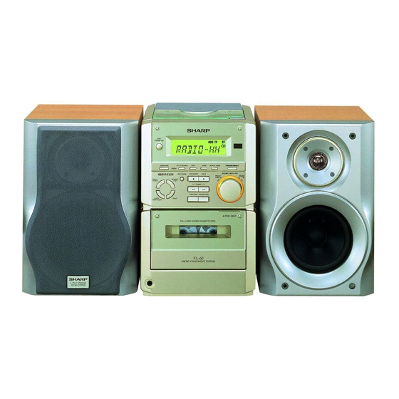
Illustration: XL-60H
Illustration: XL-70H
SAFETY PRECAUTION FOR SERVICE MANUAL .......................................................................................................... 2
IMPORTANT SERVICE NOTES (FOR U.K. ONLY) ......................................................................................................... 2
SPECIFICATIONS ............................................................................................................................................................ 3
NAMES OF PARTS .......................................................................................................................................................... 4
OPERATION MANUAL ..................................................................................................................................................... 6
DISASSEMBLY ................................................................................................................................................................. 8
REMOVING AND REINSTALLING THE MAIN PARTS .................................................................................................. 10
ADJUSTMENT ................................................................................................................................................................ 12
RDS ................................................................................................................................................................................ 13
TEST MODE ................................................................................................................................................................... 14
ERROR LIST .................................................................................................................................................................. 20
NOTES ON SCHEMATIC DIAGRAM ............................................................................................................................. 21
TYPE OF TRANSISTOR AND LED ................................................................................................................................ 21
BLOCK DIAGRAM .......................................................................................................................................................... 22
SCHEMATIC DIAGRAM ................................................................................................................................................. 26
WIRING SIDE OF P.W.BOARD ...................................................................................................................................... 32
WAVEFORMS OF CD CIRCUIT ..................................................................................................................................... 36
TROUBLESHOOTING .................................................................................................................................................... 37
FUNCTION TABLE OF IC .............................................................................................................................................. 43
LCD SEGMENT .............................................................................................................................................................. 52
SERVICE MANUAL
CONTENTS
SHARP CORPORATION
- 1 -
XL-60H/XL-70H Micro Component System consisting of XL-60H/
XL-70H (main unit) and CP-XL60H/CP-XL70H (speaker system).
• In the interests of user-safety the set should be restored to its original
condition and only parts identical to those specified should be used.
• Note for users in U.K.
Recording and playback of any material may require consent,
which SHARP is unable to give. Please refer particularly to the
provisions of Copyright Act 1956, the Dramatic and Musical
Performers Protection Act 1956, the Performers Protection Acts
1963 and 1972 and to any subsequent statutory enactments and
orders.
This document has been published to be used
for after sales service only.
The contents are subject to change without notice.
XL-60H/70H
No. S4031XL60H///
XL-60H
XL-70H
Page
Advertisement
Table of Contents

Related Manuals for Sharp XL-60H


Summary of Contents for Sharp XL-60H
-
Page 1: Table Of Contents
• Note for users in U.K. Recording and playback of any material may require consent, which SHARP is unable to give. Please refer particularly to the provisions of Copyright Act 1956, the Dramatic and Musical Performers Protection Act 1956, the Performers Protection Acts 1963 and 1972 and to any subsequent statutory enactments and orders. -
Page 2: Safety Precaution For Service Manual
XL-60H/70H SAFETY PRECAUTION FOR SERVICE MANUAL Precaution to be taken when replacing and servicing the Laser Diode Properties Laser Pickup. Material: GaAIAs The AEL (Accessible Emission Level) of Laser Power Output Wavelength: 780 nm Emission Duration: continuous for this model is specified to be lower than Class I Requirements. -
Page 3: Specifications
XL-60H/70H FOR A COMPLETE DESCRIPTION OF THE OPERATION OF THIS UNIT, PLEASE REFER TO THE OPERATION MANUAL. SPECIFICATIONS XL-60H/70H General Cassette deck section Power source: AC 230 V, 50 Hz Frequency response: 50 - 14,000 Hz (Normal tape) Power consumption:... -
Page 4: Names Of Parts
XL-60H/70H NAMES OF PARTS XL-60H/70H 1 2 3 5 6 7 8 9 Front panel 1. Timer Indicator 2. Record Indicator 3. Sleep Indicator 4. (CD) Random Indicator 5. (CD/TUNER) Memory Indicator 6. RDS Indicator 13 14 15 7. Traffic Programme Indicator 8. - Page 5 XL-60H/70H Speaker section CP-XL60H 1. Tweeter 2. Woofer 3. Bass Reflex Duct 4. Speaker Wire CP-XL70H 1. Tweeter 2. Woofer 3. Bass Reflex Duct 4. Speaker Wire XL-60H/70H Remote control 1. Remote Control Transmitter LED Tuner control section 2. Programme Type/Traffic Information Search Button 3.
-
Page 6: Operation Manual
XL-60H/70H OPERATION MANUAL – 6 –... -
Page 7: Listening To A Cd
XL-60H/70H Listening to a CD Check the supplied accessories Press the ON/STAND-BY button to turn Label side up OPEN/CLOSE the power on. Press the FUNCTION button until “CD” or “NO DISC” appears. Press the OPEN/CLOSE button to AM loop aerial ×1 Remote control ×... -
Page 8: Disassembly
XL-60H/70H DISASSEMBLY XL-60H/70H Caution on Disassembly (A1)x1 Follow the below-mentioned notes when disassembling Top Cabinet ø3x10mm the unit and reassembling it, to keep it safe and ensure CD PWB excellent performance: (B2)x1 1. Take cassette tape and compact disc out of the unit. - Page 9 XL-60H/70H CP-XL60H Front Panel STEP REMOVAL PROCEDURE FIGURE Speaker 1. Net Frame ... (A1) x1 2. Front panel ..(A2) x1 3. Screw ....(A3) x4 Tape Mechanism Open Speaker Box Tweeter Cassette (K1)x4 Holder ø2.5x10mm (A2)x1 (A1)x1 Figure 9-1 (M2)x1 ø2.5x10mm...
-
Page 10: Removing And Reinstalling The Main Parts
XL-60H/70H REMOVING AND REINSTALLING THE MAIN PARTS TAPE MECHANISM SECTION (A2)x1 (A2)x1 ø2x7mm ø2x3mm Perform steps 1 to 8 and 10 of the disassembly method to remove the tape mechanism. (See page 8.) (A1)x2 ø2x8mm How to remove the record / playback and erase heads (See Fig. -
Page 11: Cd Mechanism Section
XL-60H/70H How to remove the tape mechanism PWB (F1)x1 (F2)x1 ø2x3mm (See Fig. 11-1.) Tape ø2x8mm Mechanism 1. Remove the screws (F1) x 1 pc., to remove the tape Tape mechanism PWB. Mechanism 2. Remove the screws (F2) x 1 pc. -
Page 12: Adjustment
XL-60H/70H ADJUSTMENT TUNER SECTION MECHANISM SECTION • Driving Force Check fL: Low-range frequency fH: High-range frequency Torque Meter Specified Value • AM IF/RF Play: TW-2412 Over 80 g Signal generator: 400 Hz, 30%, AM modulated Display Frequency Frequency Setting/ Instrument •... -
Page 13: Rds
‘Pop’ with their regular programme signals. For exam- With the XL-60H/XL-70H, you can search for and strumental music, and vocal or cho- which is usually US or UK inspired ple, the stations send their station names, and in- receive the following PTY, TP and TA signals. -
Page 14: Test Mode
XL-60H/70H TEST MODE The test mode applied to this microcomputer has three modes, namely ordinary test mode to be used for adjustment or measurement, aging test mode to be used for aging test, and self-diagnosis test mode for self-inspection in case of final product inspection. - Page 15 XL-60H/70H 2. Step 2 Mode When the "PLAY" button is pressed in this mode, the laser lighting command LDON (8400) is sent, and the laser is turned on. Other operations are not performed. If the following buttons are pressed in this state, the operation is performed as follows.
- Page 16 XL-60H/70H 5. Step 5 Mode The CD initialization operation flow is executed to the end, the mute is set to off, and playback is started. Even when the playback reaches the outermost periphery of disc, the operation does not stop. The LCD display indicates the playback past time as in case of ordinary CD playback.
- Page 17 XL-60H/70H 3. Preset frequencies for various destinations (random preset memory) BAND Europe 2, 4 Europe 2, 4 BAND BAND Europe 2, 4 FM 87.50 MHz AM 522 kHz 16-25 FM108.00 MHz AM1620 kHz FM106.00 MHz FM 98.00 MHz AM 990 kHz FM 90.00 MHz...
- Page 18 XL-60H/70H * When the "PRESET UP" button or "PRESET DOWN" button is pressed after completion, the following indication appears. CH indication Frequency indication Time series indication of PS name indication is enabled. (for 2 seconds) (for 2 seconds) (The same as in case of Ordinary)
- Page 19 XL-60H/70H g) When 01 to 03CH were all used, scan is aborted at the frequency at which filling occurred, and the following indication appears. Number of stored stations -> Indication of stored channel -> Indication of frequency -> Return to initial FM 106.50 MHz (ST)
-
Page 20: Error List
XL-60H/70H 7. Key input diagnosis Test Mode (TEST 6) When the test mode is set, the following indication appears. This test mode is intended to check whether all the main unit buttons can be detected. Accordingly, in this test mode checking as to whether the "POWER"... -
Page 21: Notes On Schematic Diagram
XL-60H/70H NOTES ON SCHEMATIC DIAGRAM • Resistor: • The indicated voltage in each section is the one measured To differentiate the units of resistors, such symbol as K and by Digital Multimeter between such a section and the chas- M are used: the symbol K means 1000 ohm and the symbol sis with no signal given. -
Page 22: Block Diagram
XL-60H/70H AM LOOP CNP301 ANTENNA FM MUTE LEVEL L341 T302 SWITCHING AM ANT VR351 BALUN VD301-1 10K(B) R_MUTE Q351 SVC348S AM OSC OUT X351 456kHz 14 13 VD301-2 SVC348S IC303 T306 FM IF DET./FM MPX./AM IF AM OSC. LA1832 AM IF... - Page 23 XL-60H/70H IC201 KIA4558P SURROUND CONTROL R-CH IN R-CH OUT A_12V Q201 IC201 KIA4558P IC521 X521 RDS CIRUIT 456kHz Q203 LC72723M AMP. L-CH OUT SURROUND Q521 ON/OFF L-CH IN A GND CONT A_12V RDS CLK RDS DATA R-CH OUT REC R CH...
- Page 24 XL-60H/70H COM3 COM2 COM1 COM0 VLC3 VLC2 VLC1 OSC2 OSC1 X701 8MHz X702 MMOD 32.768kHz SW700 CNP706 CNS706 VREF CLID_SW SW709-SW710 KEY1 DOWN SW711-SW718 KEY2 D701-709 MODEL SW721-SW728 CLID_PRO D_GND TAPE_SW CFW701 VREF+ 26 27 28 29 30 31 32...
- Page 25 XL-60H/70H LCD701 LCD DISPLAY CL ID_DW CLID_UP CLID_PRO CL ID_SW COM3 SEG25 CD_RES COM2 SEG26 COM1 SEG27 BUCK COM0 TO CD PWB SEG28 BUS3 VLC3 SEG29 BUS2 VLC2 SEG30 BUS1 VLC1 SEG31 BUS0 SEG32 CD_STB OSC2 SEG33 PU_IN OSC1 BUCK...
-
Page 26: Schematic Diagram
XL-60H/70H AM TRACKING fL LOW PASS FILTER AM ANT SWITCHING C330 FM MUTE L354 12P(CH) LEVEL Q351 R358 C343 KRC104 M 8.2K VR351 C332 C302 C331 10K(B) 0.022 VD301 0.001 0.047 4.7V SVC348S T302 (0V) C371 L353 R361 C329 1/50 D301 0.022... - Page 27 XL-60H/70H R202 R529 8.2K C204 C202 1/50 R528 0.0056 R204 IC201 C212 C214 100K C527 0.0033 4.7/50 KIA4558P SURROUND R534 R206 R212 R214 C216 R218 R216 2.7K 1/50 CONTROL 1.2K 1.2K 2.5V C526 16 15 14 13 12 11 10...
- Page 28 XL-60H/70H DISPLAY PWB-A2 SW728 SW718 VOLUME/JOG SURROUND SW727 SW717 R714 R705 FUNCTION PTY.PI 5.6K 5.6K SW726 R706 SW716 R715 TUNING DOWN 3.9K 3.9K SW725 SW715 R707 R716 STOP/ CLEAR 2.7K ASPM 2.7K R708 SW724 SW714 R717 2.2K REC. PAUSE DISPLAY MODE 2.2K...
- Page 29 XL-60H/70H LCD701 LCD DISPLAY 97 96 95 94 93 92 91 90 89 88 87 86 85 84 83 82 81 80 79 78 77 76 SEG24 SEG25 2.5V SEG26 2.5V 2.5V SEG27 2.5V SEG28 CLID_DW 2.5V SEG29 CLID_UP 2.5V...
- Page 30 XL-60H/70H IC805 CD SIGNAL TA7291S CD LID PWB-A9 R872 2.2(1/2W) CFW806 C871 47/16 PU_IN SW802 CD LID CD_STB BUS0 R874 2.2K BUS1 BUS2 BUS3 BUCK R876 R877 150K CLID_SW CLID_PRO R880 CLID_UP CLID_DW R813 L803 10µH C825 0.056 R814 R817 R818 3.3K...
- Page 31 XL-60H/70H CD PWB-A3 IC805 TA7291S MOTOR DRIVER M801 CD LID MOTOR C872 CFW807 SW730 CD LID OPEN/CLOSE OPEN/CLOSE SWITCH PWB-A6 C861 0.001 CD_L A_GND CD_R L804 TO MAIN PWB 2.2µH M_GND CNP605 M_12V P27 8-H D_GND Q861 CD_6.2V L803 2SB562 C 10µH...
-
Page 32: Wiring Side Of P.w.board
XL-60H/70H ANTENNA TERMINALS SO601 FROM POWER SO401 SPEAKER AM LOOP ANTENNA FROM AMP.PWB SO301 VIDEO/AUX TERMINALS ANTENNA POWER FM 75 OHMS P35 11-H L-CH R-CH CNS604 R-CH L-CH CNS652 P35 8-A CNP301 R346 C376 L342 C618 C617 C637 Q301 L341... - Page 33 XL-60H/70H DISPLAY PWB-A2 TO MAIN PWB P32 6-G CNP703 R746 R743 R778 R747 R775 CNS702 1 2 3 4 5 6 7 8 9 R741 R779 R740 CNS703 CLOCK/TIMER/ R780 SW709 SW722 SLEEP R739 ON/STAND/BY BASS/ X702 TREBLE SW710 R749...
-
Page 34: Digital Out
XL-60H/70H PICKUP UNIT CD LID PWB-A9 CD MOTOR PWB-C SW802 CD LID NSW801 PICK UP IN NM802 SPINDLE MOTOR NM801 SLED MOTOR CFW806 CFW807 OPEN/CLOSE TO MAIN PWB SWITCH PWB-A6 IC805 P32 1-F M801 CD LID CNP605 MOTOR CNS804 CNP804... - Page 35 XL-60H/70H TO MAIN PWB FROM DISPLAY PWB CNP652 P32 1-A CNS707 CNS651 P33 12-F CNS652 POWER PWB-B1 BI652 CNP707 BI651 T651 R685 MAIN POWER TRANSFORMER R686 F652 T1.25A L 250V Q683 E C B LF651 C688 LINE FILTER R683 D685...
-
Page 36: Waveforms Of Cd Circuit
XL-60H/70H WAVEFORMS OF CD CIRCUIT NO DISC FOCUS SEARCH STOP PLAY TMAX IC802 48pin IC802 30pin SBOK IC804 26pin IC802 12pin IC804 25pin IC802 55pin FOCUS SEARCH TOC IL STOP PLAY IC802 57pin IC802 46pin IC802 43pin IC802 49pin IC802 46pin... -
Page 37: Troubleshooting
XL-60H/70H TROUBLESHOOTING When the CD does not function When the CD section does not operate when the objective lens of the optical pickup is dirty, this section may not operate. Clean the objective lens, and check the playback operation. When this section does not operate even after the above step is taken, check the following items. - Page 38 XL-60H/70H Make sure that the disc is normal, and set the CD TEST MODE (STEP 1). Is the measured voltage as specified in circuit diagram? Check the main unit power supply circuit. Is "Er-CD01" displayed"? Move the pickup to most internal circumference side of disc.
- Page 39 XL-60H/70H • Laser failure. Is +6.2V applied to the emiter of Q861 ? Check the PWB pattern between pin 16 of CNS602 and emiter of Q861. Check the peripheral parts of IC804 and Q861. Is +5V applied to the collector of Q861 ?
- Page 40 XL-60H/70H • Focus servo sawtooth wave failure. IC802 is faulty. Is sawtooh wave output to the pin 48 (FOO) of IC802 ? 1.5~2.5sec Check the PWB pattern between pin 16 of CNS602 and IC804. Is +6.2V applied to the pins 1 and 30 (VCC) of IC804 ?
- Page 41 XL-60H/70H • HF error. Is output (tracking error signal) obtained at the pins 46 (TEI) Optical pickup failure. Is output obtained at the pins 2 and and 47 (TEZI) of IC802 the CD TEST MODE "STEP 4" is 5 of BI802/CNS802 changed to "STEP 5"?
- Page 42 XL-60H/70H • Track search failure Check as stated in item "SLED MOTOR OPERATION FAILURE". Does the sled motor run in FF/REW state when the SERVO TEST MODE "STEP1" is set? Is the following wave output to the pin 49 (TRO) of IC802 IC802 failure.
-
Page 43: Function Table Of Ic
XL-60H/70H FUNCTION TABLE OF IC IC401 VHiLC75342M-1: Function/Volume Equalizer (LC75342M) Pin No. Port Name Function Serial data and clock input pin for control. Chip enable pin. Data written into an internal latch in a timing of [H] -> [L]. Each analog switch is activated. - Page 44 XL-60H/70H IC401 VHiLC75342M-1: Function/Volume Equalizer (LC75342M) TEST VSS CE CL VDD Vref LOUT ROUT LBASS2 RBASS2 LBASS1 RBASS1 LTRE RTRE RSEL0 LSEL0 14 15 16 17 Figure 44 BLOCK DIAGRAM OF IC – 44 –...
- Page 45 XL-60H/70H IC701 RH-iX0026SJZZ: System Control Microcomputer (IX0026SJ) (1/2) Terminal Name Input/Output Function Pin No. COM3-COM0 Output LCD common output terminal. VLC3-VLC1 — LCD power supply terminal. — Microcomputer power supply +5V. OSC2 Output Oscillator ground terminal for main clock. f=8MHz...
- Page 46 XL-60H/70H IC701 RH-iX0026SJZZ: System Control Microcomputer (IX0026SJ) (2/2) Terminal Name Input/Output Pin No. Function SEG46 P63/A3 Output Electric JOG dial UP. SEG45 P64/A4 Output Electric JOG dial DOWN. SEG44 P65/A5 Output Electric CD lid OPEN. SEG43 P66/A6 Output Electric CD lid CLOSE.
- Page 47 XL-60H/70H IC801 VHiTA2109F/-1:Servo Pre Amp. (TA2109F) Pin No. Terminal Name Input/Output Function — Power voltage terminal Input Main beam amp input terminal Input Main beam amp input terminal Input Sub-beam amp input terminal Input Sub-beam amp input terminal Input Monitor photodiode amp input terminal...
- Page 48 XL-60H/70H IC802 VHiTC9462F/-1: Servo/Signal Control (TC9462F) (1/3) Function Port Name Input/Output Pin No. TEST0 Input Test mode terminal. To be opened usually. /HSO Output Playback speed mode flag output terminal. /UHSO Output /UHSO /HSO Playback speed x1 speed playback x2 speed playback x4 speed playback —...
- Page 49 XL-60H/70H IC802 VHiTC9462F/-1: Servo/Signal Control (TC9462F) (2/3) Function Port Name Input/Output Pin No. AVDD — Analog system power terminal. RFCT Input RFRP signal center level input terminal. RFZI Input RFRP zero cross input terminal. RFIP Input RF ripple signal input terminal.
- Page 50 XL-60H/70H IC802 VHiTC9462F/-1: Servo/Signal Control (TC9462F) (3/3) Function Port Name Input/Output Pin No. DVDD — D/A converting section power terminal. — Reference voltage terminal. Output L channel data forward rotation output terminal. DVSL — L channel D/A converting section power terminal.
- Page 51 XL-60H/70H IC804 VHiLA6541D/-1: Focus/Tracking/Spin/Sled Driver (LA6541D) Pin No. Port Name Function Power (short-circuited to pin 30) MUTE All BTL AMP output ON/OFF VIN1 BTL AMP1 input terminal BTL AMP1 input terminal (for gain adjustment) BTL AMP1 output terminal (noninversion side)
-
Page 52: Lcd Segment
XL-60H/70H LCD701: RV-LX0007SJZZ LCD Display 1 2 3 4 5 6 7 8 9 10 11 12 13 14 15 16 17 18 19 20 21 22 23 24 25 26 27 28 29 30 31 32 33 34 35 36 37 38 39 40 41 42... -
Page 53: Parts Guide
XL-60H/70H PARTS GUIDE XL-60H MODEL XL-70H XL-60H/XL-70H Micro Component System consisting of XL-60H/ XL-70H (main unit) and CP-XL60H/CP-XL70H (speaker system). “HOW TO ORDER REPLACEMENT PARTS” To have your order filled promptly and correctly, please furnish the For U.S.A. only following information. - Page 54 XL-60H/70H PRICE PRICE PARTS CODE DESCRIPTION PARTS CODE DESCRIPTION RANK RANK ZD601 VHEMTZJ130A-1 AC Zener,13V,MTZJ13A XL-60H/70H ZD602 VHEMTZJ7R5C-1 AC Zener,7.5V,MTZJ7.5C ZD681 VHEMTZJ6R8A-1 AA Zener,6.8V,MTZJ6.8A INTEGRATED CIRCUITS ZD682 VHEMTZJ5R6B-1 AD Zener,5.6V,MTZJ5.6B ZD701 VHEMTZJ3R3B-1 AA Zener,3.3V,MTZJ3.3B IC101 VHIBA3126N/-1 AF Head Selector,BA3126N FILTERS...
- Page 55 XL-60H/70H PRICE PRICE DESCRIPTION PARTS CODE DESCRIPTION PARTS CODE RANK RANK AB 47 µF,16V,Electrolytic AC 470 µF,25V,Electrolytic C209 RC-GZA476AF1C C620 RC-GZV477AF1E AA 0.0033 µF,50V AB 100 µF,25V,Electrolytic C211,212 VCKYTV1HB332K C621 RC-GZA107AF1E AB 4.7 µF,50V,Electrolytic AB 0.022 µF,50V C213,214 RC-GZA475AF1H C622 VCKYPA1HF223Z AB 1 µF,50V,Electrolytic...
- Page 56 XL-60H/70H PRICE PRICE DESCRIPTION PARTS CODE PARTS CODE DESCRIPTION RANK RANK AA 0.001 µF,50V C861 VCKYPA1HB102K R213~216 VRS-TV2AB123J AA 12 kohms,1/10W AA 0.0022 µF,50V C862 VCKYPA1HB222K R217 VRD-ST2CD123J AA 12 kohms,1/6W C863 VCKYTV1HB471K AA 470 pF,50V R218 VRS-TV2AB122J AA 1.2 kohms,1/10W AB 47 µF,16V,Electrolytic...
- Page 57 XL-60H/70H PRICE PRICE PARTS CODE DESCRIPTION PARTS CODE DESCRIPTION RANK RANK R701 VRD-ST2CD103J AA 10 kohm,1/6W R907 VRD-ST2CD103J AA 10 kohm,1/6W R702 VRS-TV2AB103J AA 10 kohm,1/10W R909 VRS-TV2AB183J AA 18 kohms,1/10W R705 VRD-ST2CD562J AA 5.6 kohms,1/6W R910 VRS-TV2AB333J AA 33 kohms,1/10W...
-
Page 58: Rear Panel
AE Switch,Push Type [Pickup In] LANGF0011SJZZ AD Bracket,Heat Sink, Power Amp. PWB CABINET PARTS LANGT0001SJFW AD Bracket,Power Amp. PWB/Main PWB CPNLC1047SJ02 Front Panel Ass’y [XL-60H] PCOVP1001SJSB AG Cover,Heat Sink, CPNLC1047SJ04 Front Panel Ass’y [XL-70H] Power Amp. PWB 201- 1 ———— —... -
Page 59: Woofer
AK Spacer Board SPAKA0052SJZZ Packing Add.,Side 9GDHSY042SPK03 J AH Duct Pipe [For Europe Only] 9GDHSY041SPK06 J AK Cord,Speaker SPAKC0101SJZZ AM Packing Case [XL-60H] 9GDHSY041SPK08 J AG Screw,ø4×16mm SPAKC0103SJZZ AQ Packing Case [XL-70H] HSY093SPK040 Label,Specifications SPAKP0005SJZZ AC Polyethylene Bag,Unit PGUMM0001SJSB J... - Page 60 XL-60H/70H XL-60H/70H 306-2 306-1 306-3 703x2 NM802 NM801 305x2 NSW801 PWB-C Figure 7 CD MECHANISM EXPLODED VIEW – 7 –...
- Page 61 XL-60H/70H XL-60H/70H 615x2 PWB-A9 613x2 PWB-A6 PWB- 216-2 BELT CONNECTION 216-1 616x5 Motor(M901) FF/REW PWB- Clutch 603x2 Main MECHANISM Belt PWB-A10 PWB-A10x3 FF/REW Flywheel Belt 601x3 PWB-A3 PWB-A7 610x2 PWB-A4 PWB-A2 603 601x2 608x2 M701 609x3 608x2 LCD701 613x2 609x3...
- Page 62 XL-60H/70H CP-XL60H TWEETER SP603(L-CH) TWEETER SP604(R-CH) SP603(L-CH) SP604(R-CH) BLACK WOOFER SP601(L-CH) BLACK BLACK WITH WHITE LINE SP602(R-CH) WOOFER SP601(L-CH) SP602(R-CH) SP603(L-CH) SP604(R-CH) 709x4 SP601(L-CH) SP602(R-CH) 707x4 Figure 9 SPEAKER EXPLODED VIEW (1/2) – 9 –...
- Page 63 XL-60H/70H CP-XL70H Capacitor (706) TWEETER SP603(L-CH) SP604(R-CH) Black with White Line Black with WOOFER White Line SP601(L-CH) SP602(R-CH) 704x4 SP603(L-CH) SP604(R-CH) 708x4 SP601(L-CH) SP602(R-CH) TWEETER SP603(L-CH) SP604(R-CH) Capacitor 3.3µF,50V 707x4 WOOFER SP601(L-CH) SP602(R-CH) Figure 10 SPEAKER EXPLODED VIEW (2/2) – 10 –...
-
Page 64: Packing Method (For U.k. Only)
SPAKA0045SJZZ 3. FM Antenna QANTW0002SJZZ Speaker 4. Remote Control RRMCG0014SJSB 5. Packing Add., Left/Right SPAKA0043SJZZ CP-XL70H 6. Packing Case [XL-60H] SPAKC0110SJZZ 1. Polyethylene Bag, Speaker 9GDHSY041SPK10 6. Packing Case [XL-70H] SPAKC0111SJZZ 2. Packing Add., Top/Bottom, SPAKA0047SJZZ 7. Polyethylene Sheet, Unit...
Need help?
Do you have a question about the XL-60H and is the answer not in the manual?
Questions and answers
When i push the door of the cassette it´s Not close correctly. ? Thank you
The cassette door on the Sharp XL-60H may not be closing correctly due to issues with the cassette holder, cassette holder damper gear, or cassette holder spring. If any of these components are damaged, misaligned, or obstructed, the door may not function properly. Checking for obstructions, ensuring proper alignment, and inspecting these parts for wear or damage can help resolve the issue.
This answer is automatically generated
I canot close correctly the door of the cassette
To fix the cassette door on a Sharp XL-60H that won't close correctly, check the following:
1. Inspect for Obstructions – Ensure there is no tape or debris blocking the door mechanism.
2. Check the Cassette Holder Damper Gear – The part labeled as "CGERH0001SJ01" may be misaligned or damaged.
3. Verify the Spring Mechanism – The cassette holder spring ("MSPRD0006SJFJ") may need adjustment or replacement.
4. Ensure Proper Alignment – Make sure the cassette holder and its window are properly positioned.
5. Tighten or Replace Screws – Loose or missing screws (e.g., "LX-EZ0001SJFN" or "XEBSD25P10000") might be affecting the door’s function.
If these steps do not resolve the issue, consider ordering replacement parts for damaged components.
This answer is automatically generated