Table of Contents
Advertisement
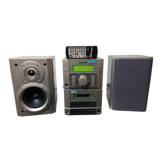
Illustration: XL-560/570,CP-XL560U/570U
IMPORTANT SERVICE NOTES (FOR U.S.A. ONLY) ...................................................................................................... 2
SPECIFICATIONS ............................................................................................................................................................ 2
NAMES OF PARTS .......................................................................................................................................................... 3
OPERATION MANUAL (FOR XL-560/570) ...................................................................................................................... 5
QUICK GUIDE (FOR XL-560/570) .................................................................................................................................... 7
DISASSEMBLY ................................................................................................................................................................. 8
REMOVING AND REINSTALLING THE MAIN PARTS .................................................................................................... 9
ADJUSTMENT ................................................................................................................................................................ 10
TEST MODE ................................................................................................................................................................... 11
NOTES ON SCHEMATIC DIAGRAM ............................................................................................................................. 15
TYPE OF TRANSISTOR AND LED ................................................................................................................................ 15
BLOCK DIAGRAM .......................................................................................................................................................... 16
SCHEMATIC DIAGRAM / WIRING SIDE OF P.W.BOARD ............................................................................................ 20
WAVEFORMS OF CD CIRCUIT ..................................................................................................................................... 27
TROUBLESHOOTING .................................................................................................................................................... 28
FUNCTION TABLE OF IC .............................................................................................................................................. 34
LCD SEGMENT .............................................................................................................................................................. 42
PARTS GUIDE/EXPLODED VIEW
DIFFERENCE BETWEEN XL-560 AND XL-570/570C
SERVICE MANUAL
CONTENTS
CD Lid Panel
None
Speaker Cord
None
SHARP CORPORATION
- 1 -
XL-560 desk top audio system consisting of
XL-560 (main unit) and
CP-XL560U (speaker system).
XL-570 desk top audio system consisting of
XL-570 (main unit) and
CP-XL570U (speaker system).
XL-570C desk top audio system consisting of
XL-570C (main unit) and
CP-XL570U (speaker system).
• In the interests of user-safety the set should be restored to its original
condition and only parts identical to those specified should be used.
XL-570/570C
XL-560
Used
Used
This document has been published to be used
for after sales service only.
The contents are subject to change without notice.
XL-560,570/C
No. S6941XL560///
XL-560
XL-570
XL-570C
Page
Advertisement
Table of Contents


Need help?
Do you have a question about the XL-560 and is the answer not in the manual?
Questions and answers