Table of Contents
Advertisement
SAFETY PRECAUTION FOR SERVICE MANUAL ........................................................................................................... 2
IMPORTANT SERVICE NOTES (FOR U.K. ONLY) .......................................................................................................... 3
SPECIFICATIONS ............................................................................................................................................................. 3
NAMES OF PARTS ........................................................................................................................................................... 4
OPERATION MANUAL ..................................................................................................................................................... 6
QUICK GUIDE ................................................................................................................................................................... 7
DISASSEMBLY .................................................................................................................................................................. 9
REMOVING AND REINSTALLING THE MAIN PARTS ................................................................................................... 12
ADJUSTMENT ................................................................................................................................................................. 13
NOTES ON SCHEMATIC DIAGRAM .............................................................................................................................. 19
WAVEFORMS OF CD CIRCUIT ...................................................................................................................................... 20
BLOCK DIAGRAM ........................................................................................................................................................... 21
WIRING SIDE OF P.W.BOARD / SCHEMATIC DIAGRAM .............................................................................................. 24
VOLTAGE ........................................................................................................................................................................ 43
TROUBLESHOOTING ..................................................................................................................................................... 44
FUNCTION TABLE OF IC ................................................................................................................................................ 48
FL DISPLAY ...................................................................................................................................................................... 54
WIRING OF PRIMARILY SUPPLY LEADS (FOR U.K. ONLY) ....................................................................................... 54
REPLACEMENT PARTS LIST/EXPLODED VIEW
SERVICE MANUAL
CONTENTS
SHARP CORPORATION
- 1 -
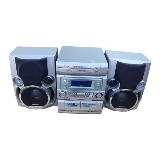
CD-BA2010H
CD-BA2010H Mini Component System consisting of
CD-BA2010H (main unit) and CP-BA2010H (speaker system).
• In the interests of user-safety the set should be restored to its
original condition and only parts identical to those specified be
used.
• Note for users in U.K.
Recording and playback of any material may require consent
which SHARP is unable to give. Please refer particularly to the
provisions of Copyright Act 1956, the Dramatic and Musical
Prefomers Protection Act 1956, the Preformers Protection Acts
1963 and 1972 and to any subsequent statutory enactments and
orders.
This document has been published to be used
for after sales service only.
The contents are subject to change without notice.
CD-BA2010H
No. S5036CDA2010H
Page
Advertisement
Table of Contents

Related Manuals for Sharp CD-BA2010H


Summary of Contents for Sharp CD-BA2010H
-
Page 1: Table Of Contents
• Note for users in U.K. Recording and playback of any material may require consent which SHARP is unable to give. Please refer particularly to the provisions of Copyright Act 1956, the Dramatic and Musical Prefomers Protection Act 1956, the Preformers Protection Acts 1963 and 1972 and to any subsequent statutory enactments and orders. -
Page 2: Safety Precaution For Service Manual
CD-BA2010H (Except for U.K.) SAFETY PRECAUTION FOR SERVICE MANUAL Precaution to be taken when replacing and servicing the Laser Pickup. The AEL (Accessible Emission Level) of Laser Power Output for this model is specified to be lower than Class I Requirements. -
Page 3: Important Service Notes (For U.k. Only)
CD-BA2010H IMPORTANT SERVICE NOTES (FOR U.K. ONLY) WITHSTANDING Before returning the unit to the customer after completion of a VOLTAGE TESTER PROBE repair or adjustment it is necessary for the following withstand voltage test to be applied to ensure the unit is safe for the customer to use. -
Page 4: Names Of Parts
CD-BA2010H NAMES OF PARTS CD-BA2010H Front panel . (CD) Disc Tray . (CD) Disc Skip Button . (CD) Disc Number Select Buttons . (CD) Open/Close Button . Extra Bass Indicator . Spectrum Analyzer/Volume Level Indicator . (CD) Disc Number Indicators . - Page 5 CD-BA2010H Rear panel . AC Power Lead . FM 75 Ohms Aerial Socket . AM Loop Aerial Socket . Speaker Terminals . Video/Auxiliary (Audio Signal) Input Sockets Remote control . Remote Control Transmitter LED CD control section . Disc Number Select Buttons .
-
Page 6: Operation Manual
CD-BA2010H OPERATION MANUAL – 6 –... -
Page 7: Quick Guide
CD-BA2010H – 7 –... - Page 8 CD-BA2010H – 8 –...
-
Page 9: Disassembly
CD-BA2010H DISASSEMBLY Note 1: Caution on Disassembly How to open the changer manually. (Fig. 10-1) Follow the below-mentioned notes when disassembling 1. In this state, turn fully the lock lever in the arrow direction the unit and reassembling it, to keep it safe and ensure through the hole on the loading chassis bottom. -
Page 10: Bottom View
CD-BA2010H (F1)x1 ø3x10mm (F3)x1 (F1)x1 ø3x8mm Front Panel Lock Lever Headphones (F2)x2 CD Player Unit (G2)x1 (Bottom View) Power Supply (G2)x1 (F2)x2 Figure 10-1 (G1)x2 ø3x8mm Figure 10-4 Switch PWB Clamp Lever (K4)x1 (H1)x1 (J2)x1 (J1)x2 (K3)x1 (K3)x1 CD Player Unit ø3x10mm... - Page 11 CD-BA2010H Slide Chassis (Q2)x3 (N1)x3 Mechanism Loading Motor (Q1)x1 (Q1)x1 (N1)x3 Figure 11-1 (R1)x5 (P1)x1 Slide CD Servo ø3x8mm Chassis (P3)x2 Figure 11-3 (P2)x2 (P3)x2 Figure 11-2 CP-BA2010H STEP REMOVAL PROCEDURE FIGURE Woofer 1. Front Panel .... (A1) x1 11-4 2.
-
Page 12: Removing And Reinstalling The Main Parts
CD-BA2010H REMOVING AND REINSTALLING THE MAIN PARTS TAPE MECHANISM SECTION TAPE 2 Perform steps 1 to 7 and 11 of the disassembly method to Record/Playback Head remove the tape mechanism. How to remove the record/playback and erase heads (TAPE 2) (See Fig. 12-1) 1. -
Page 13: Adjustment
CD-BA2010H CD MECHANISM SECTION Perform steps 1, 2, 3, 12 and 15 of the disassembly method to remove the CD mechanism. How to remove the loading motor Loading Motor (See Fig. 13-1) 1. Bend the hooks (A1) x 5 pcs., to remove the loading motor. -
Page 14: Tuner Section
CD-BA2010H • FM TUNER SECTION Notes: fL: Low-range frequency 1: Description of the "FM IF Adjustment" is not carried on this fH: High-range frequency Manual. It is because the IF coil in the FM front end section • AM IF/RF... - Page 15 CD-BA2010H – 15 –...
- Page 16 Preset memory takes priority of switching TN—ON station. Therefore ASPM is usefull not only for PTY search but also for rapid EON switching. Anyway CD-BA2010H EON is basically stand-by and receiving method, along with the Guidelines for EON implementation. – 16 –...
- Page 17 CD-BA2010H EON summary notice for reference 1. EON-TI/PTY EON stand-by can be set, only when EON ind. Lights up. While EON ind. Goes out (NO EON STATION), EON stand-by can't be set. If the EON button is pressed, then “NO EON” is indication the display.
- Page 18 CD-BA2010H – 18 –...
-
Page 19: Notes On Schematic Diagram
CD-BA2010H NOTES ON SCHEMATIC DIAGRAM • The indicated voltage in each section is the one measured • Resistor: by Digital Multimeter between such a section and the chas- To differentiate the units of resistors, such symbol as K and sis with no signal given. -
Page 20: Waveforms Of Cd Circuit
CD-BA2010H WAVEFORMS OF CD CIRCUIT Stopped Stopped 1999/04/05 17:33:17 CH1=500mV CH3=500mV 500ms/div CH1=500mV CH3=1V CH4=1V 500ms/div DC 10:1 DC 10:1 (500ms/div) DC 10:1 DC 10:1 DC 10:1 (500ms/div) NORM:20kS/s NORM:20kS/s PDO1 IC2 1 IC2 24 PDO2 IC2 2 IC2 23... -
Page 21: Block Diagram
CD-BA2010H OPEN/ CLAMP DISC CLOSE NUMBER UP/DOWN MOTOR TO MAIN SECTION TO DISPLAY SECTION (TO IC601) 9 10 75 76 45 46 47 48 32 31 30 LC78641E SERVO/SIGNAL CONTROL CONT5 SLD0 XOUT SPD0 16.9344MHz VDD5V 5 18 36 44 49 50... - Page 22 CD-BA2010H SO301 ANTENNA FM IF AMP. TERMINAL FM IF FM IF AM IF FE301 QT21 CF301 Q301 CF302 FM FRONT END T351 L354 FM IF IN L.P.F 2 6 7 4 5 8 9 17 19 20 18 AM LOOP ANT...
- Page 23 CD-BA2010H FL701 DISPLAY 56 57 58 M701 VOLUME MOTOR Q701-Q703 Q710-Q712 JOG701 Q713 Q714 Q716 Q715 RX701 REMOCON SENSOR 58 57 56 55 54 53 52 51 50 49 48 47 46 44 43 42 41 40 VLOAD SYS. STOP...
-
Page 24: Wiring Side Of P.w.board / Schematic Diagram
CD-BA2010H P28 4 - A TO POWER P27 11 - A SUPPLY PWB TO RDS PWB CNP304 CNS901 MAIN PWB-A1 C302 C348 R378 R373 X352 R372 Q301 R349 R388 R374 C382 C396 1 2 3 4 5 6 7 8 9 10 11... - Page 25 CD-BA2010H P27 12 - D TO DISPLAY PWB CNP701B CNS601 P30 4 - A CNP11 FC701 TO CD SERVO R113 Q128 B C E Q110 Q109 R167 BI601 3 2 1 B C E C152 R114 3 2 1 R160...
- Page 26 CD-BA2010H SWITCH PWB-A3 RD11 RD09 SW713 RD10 SW711 SW710 OPEN/ DISC 3 DISC 2 CLOSE DISPLAY PWB-A2 VOLUME MOTOR PWB-H1 Q703 SW704 1 2 3 6 7 8 9 10 11 12 13 14 15 16 17 18 19 20...
- Page 27 CD-BA2010H P24 4 - A TO MAIN PWB CNP303 CNP304 XT21 RT51 CT37 CT26 LT22 RT26 RT35 RT28 RT36 RT29 QT21 RD12 RT30 RD09 SW712 RT37 SW709 DISC DISC 1 SKIP QT22 RDS PWB-G C715 29 30 31 32 33 34 35 36 37 38 39 40 41 42 43 44 45 46 47 48 49 50 51 52 53...
- Page 28 CD-BA2010H P24 5 - A TO MAIN PWB POWER SUPPLY PWB-B CNP901 1 2 3 4 5 6 7 8 9 10 11 12 13 14 15 1617 18 19 RL901 CNS901 R967 R979 R980 R945 R946 FW801 R973 R972...
- Page 29 CD-BA2010H JK670 HEADPHONES R601 L601 WT601 17 18 19 RL901 HEADPHONES PWB-A4 C935 C965 C969 R979 R983 SO901 R943 C963 SPEAKER R980 TERMINAL L903 R945 R981 C975 C979 R946 C916 L-CH (HI) C918 C983 C934 R987 C936 R989 C977 R991...
- Page 30 CD-BA2010H P25 11 - A P27 12 - E TO DISPLAY PWB TO MAIN PWB CD SERVO PWB-C CNS601 CNS703 9 10 CNP11 CNP12 E C B ZD61 B C E 40 41 1 2 3 CNP3 CNP4 CNS3A PICKUP UNIT(306)
- Page 31 CD-BA2010H P26 6 - H TAPE MECHANISM TO DISPLAY PWB ASSEMBLY CNP702 FC702 TAPE MECHANISM PWB-E SOLENOID SOLENOID TAPE MOTOR TAPE 1 TAPE 2 P28 3 - H P28 4 - H ERASE HEAD RECORD/PLAYBACK PLAYBACK HEAD TO POWER TO POWER...
- Page 32 CD-BA2010H CD SERVO PWB-C CD SIGNAL Vref TIN1 FIN1 0.047 FIN2 TIN2 1.5M LA9235M SERVO AMP. 47/6.3 2.2/50 FIN1 0.022 0.02 100P ODRV 0.022 FIN2 RFSW 120K 6.8K AGCON TIN1 (CH) 47/10 0.01 TIN2 100/6.3 REF1 0.01 0.0047 0.022 VREF (CH) 0.33...
- Page 33 CD-BA2010H 100P 0.01 100P 100P 100P 100P 100P 100P 0.022 2.2mH EFMO VDD5V 80 79 78 77 76 75 74 73 72 71 70 69 68 67 66 65 0.022 0.047 PD01 COMMAND GENERAL INTERFACE 1.5M 100/6.3 PD02 SBCK 2.2/50...
- Page 34 CD-BA2010H MAIN PWB-A1(1/2) IC601 R-CH LC75341 A_GND AUDIO PROCESSOR P33 12 - D L-CH CNP11 CD_GND TO CD SERVO CD_+B VREF CNS601 INTERFACE C613 C602 R607 22/50 10/50 LOUT ROUT C609 C608 C607 0.1(ML) 0.1(ML) 0.1(ML) RBASS LBASS R605 C610 3.9K...
- Page 35 CD-BA2010H CD SIGNAL FM SIGNAL VIDEO SIGNAL PLAYBACK SIGNAL RECORD SIGNAL VREF C602 C614 R608 R631 C631 R633 22/50 10/50 6.8K 390P JK601 ROUT VIDEO C608 R606 R634 R632 C632 0.1(ML) 3.9K 6.8K RBASS 390P C610 0.1(ML) RTRE C612 C620...
- Page 36 CD-BA2010H RS720 RS721 100K 100K RS722 100K FL701 Q711 Q712 Q710 KTC3199GR KTC3199GR KTC3199GR R704 R701 100K 100K R716 100K C709 C715 81 82 83 84 85 86 87 88 89 90 91 92 93 94 95 96 97 98 99...
- Page 37 CD-BA2010H FL701 P33 12 - E 3 2 1 TO CD SERVO PWB CNP12 CNS703 BI703 DISPLAY PWB-A2 C725 81 82 83 84 85 86 87 88 89 90 91 92 93 94 95 96 97 98 99 0.022 VLOAD...
- Page 38 CD-BA2010H POWER SUPPLY PWB-B FM SIGNAL IC901 STK402-070 POWER AMP. 10 11 C907 C926 C906 R902 R907 220P 220P 220P C922 C928 100/50 C910 C903 R976 100/50 C904 R918 100/50 R924 C920 C921 R901 C908 R920 C901 C902 100(1/4W) 10/50...
- Page 39 CD-BA2010H HEADPHONES PWB-A4 IC902 STK402-040 POWER AMP. R601 10 11 R602 C927 220P L601 JK670 2.2mH HEADPHONES R927 C930 C920 C921 1/50 10/50 10/50 R933 0.1(1W) Q908 R934 KTC3199GR 0.1(1W) R938 D904 1SS133 R940 C924 C925 R937 0.022 0.022 R939...
- Page 40 CD-BA2010H AM SIGNAL FM SIGNAL C302 0.001 AM TRACKING fL C342 R365 0.022 T303 C331 C330 0.047 R358 C323 3.9K 0.022 (UJ) C338 C332 0.001 0.022 AM ANT. D301 1SS133 AM LOOP R336 ANTENNA D302 1SS133 VD301 SVC348S AM OSC.
- Page 41 CD-BA2010H C373 0.015 C371 1/50 L354 LOW PASS FILTER R350 C372 2.7K 1/50 C367 1/50 IC303 LA1832S FM IF DET./FM MPX./AM IF 10 11 C358 R352 1/50 C357 R355 2.2/50 3.3K T351 C356 0.001 AM IF L352 100µH ZD351 MTZJ5.1B...
- Page 42 CD-BA2010H P41 12 - E TO MAIN PWB CNP303 CNP304 RDS PWB-G RT48 RT49 CT28 47/16 LT22 2.2µH CT29 0.022 CT27 (CH) ICT21 LC72722 RDS DECORDER RT21 CT26 100K AMP. 22P(CH) QT21 CT25 KTC3199GR 560P QT22 KTA1266GR CT37 0.022 RT51 LT21 2.2µH...
-
Page 43: Voltage
CD-BA2010H VOLTAGE IC701 IC101 IC303 IC703 PIN VOLTAGE NO. VOLTAGE NO. VOLTAGE NO. VOLTAGE NO. VOLTAGE VOLTAGE NO. VOLTAGE 1.6V 0.7V 0V (0V) 2.1V (2.1V) 4.6V 4.9V 5.0V 1.6V 0V (0V) 4.5V (4.5V) 4.6V 1.6V 0.5V (0.5V) 2.1V (2.1V) 4.6V 5.0V... -
Page 44: Troubleshooting
CD-BA2010H TROUBLE SHOOTING When the CD does not function When the CD section does not operate when the objective lens of the optical pickup is dirty, this section may not operate. Clean the objective lens, and check the playback operation. When this section does not operate even after the above step is taken, check the following items. - Page 45 CD-BA2010H (1) Focus-HF system check Stopped CH1=500mV CH3=500mV 500ms/div Although a CD is inserted and the cover is closed, "NO DC 10:1 DC 10:1 (500ms/div) NORM:20kS/s DISC" is displayed. Press the OPEN/CLOSE switch (SW1) without inserting a disc, and try starting the playback operation.
- Page 46 CD-BA2010H (2) Tracking system check Check the TE waveform at pin 18 on IC1. The tracking servo is not activated. If the waveform shown in Figure 46-1 appears and soon after Check the peripheral circuits at pins 18 and 19 on IC1, pin 23 on NO DISC appears.
- Page 47 CD-BA2010H (4) PLL system check Stopped 1999/04/05 17:33:17 CH1=500mV CH3=1V CH4=1V 500ms/div DC 10:1 DC 10:1 DC 10:1 (500ms/div) NORM:20kS/s When a disc is loaded, start play operation. PDO1 The HF waveform is normal, but the TOC data cannot be PDO2 read.
-
Page 48: Function Table Of Ic
CD-BA2010H FUNCTION TABLE OF IC IC1 VHiLA9235M/-1: Servo Amp. (LA9235M) ODRV FIN1 LA9235M RFSW FIN2 AGCON 28 RF- FIN3 FIN4 26 N/C 25 PH 24 BH REF1 ODRV 23 N/C PH/BH 22 RFEV VREF 21 FE- 20 FE LDOF 19 TE-... - Page 49 CD-BA2010H IC2 VHiLC78641E-1: Servo/Signal Control (LC78641E) (1/2) Pin No. Terminal Name Input/Output Setting in Reset Function PDO1 Output – For PULL Phase-comparison output terminal for built-in VOC control. PDO2 Output – Phase-comparison output terminal for built-in VOC control. Rough servo : OFF, phase servo : ON.
- Page 50 CD-BA2010H IC2 VHiLC78641E-1: Servo/Signal Control (LC78641E) (2/2) Terminal Name Input/Output Setting in Reset Function Pin No. LVDD – – L channel Power terminal for L channel. LCHO Output 1/2VDD D/A converter L channel output terminal. LVSS – – Ground terminal for L channel. Surely connected to 0V.
- Page 51 CD-BA2010H IC701 RH-iX0333AWZZ: System Microcomputer (IX0333AW) (1/2) Pin No. Port Name Terminal Name Input/Output Function — (+) POWER SUPPLY -20dBATT Output -20dB ATTENUATOR S-BUSY Output Not used LCK1 Output LED DRIVER LCK (BU2092-2) LCK0 Output LED DRIVER LCK (BU2092-1) DP REQ...
- Page 52 CD-BA2010H IC701 RH-iX0333AWZZ: System Microcomputer (IX0333AW) (2/2) Pin No. Port Name Terminal Name Input/Output Function P119 Input TAPE 2 A-SIDE FULL PROOF P118 Input TAPE 2 B-SIDE FULL PROOF P117 MIC IN Input MIC SWITCH P116 KARAOKE LATCH/SPN A Output KARAOKE LATCH (When used.
- Page 53 CD-BA2010H IC601 VHiLC75341/-1: Audio Processor (LC75341) LOUT ROUT LBASS RBASS 0.1uF 0.1uF LTRE RTRE LSEL0 RSEL0 R1 R2 24 23 22 21 20 19 18 17 16 15 14 13 LC75341 10 11 12 Figure 53 BLOCK DIAGRAM OF IC...
-
Page 54: Fl Display
CD-BA2010H FL701 VVKBJ744GNK-1: FL Display (1G~8G) PIN CONNECTION PIN NO. 20 19 18 17 16 15 14 13 12 11 10 CONNECTION 9G 8G 7G 6G 5G 4G 3G 2G NP NP F1 F1 F1 30 29 28 27 26 25 24 23 22 21 PIN NO. -
Page 55: Parts Guide
CD-BA2010H PARTS GUIDE CD-BA2010H MODEL CD-BA2010H Mini Component System consisting of CD-BA2010H (main unit) and CP-BA2010H (speaker system). “HOW TO ORDER REPLACEMENT PARTS” To have your order filled promptly and correctly, please furnish the For U.S.A. only following information. Contact your nearest SHARP Parts Distributor to order. - Page 56 CD-BA2010H PRICE PRICE DESCRIPTION PARTS CODE PARTS CODE DESCRIPTION RANK RANK ZD802 VHEMTZJ6R2A-1 AA Zener,6.2V,MTZJ6.2A CD-BA2010H ZD803 VHEMTZJ130C-1 AB Zener,13V,MTZJ13C ZDT21 VHEDZ5R1BSB-1 AC Zener,5.1V,DZ5.1BSB INTEGRATED CIRCUITS FILTERS VHILA9235M/-1 AQ Servo Amp.,LA9235M CF301,302 RFILF0072AFZZ AG FM IF VHILC78641E-1 AV Servo/Signal Control,LC78641E...
- Page 57 CD-BA2010H PRICE PRICE PARTS CODE DESCRIPTION PARTS CODE DESCRIPTION RANK RANK AA 0.01 µF,50V AB 47 µF,25V,Electrolytic VCKYTV1HB103K C572 VCEAZA1EW476M J AC 330 µF,6.3V,Electrolytic AA 0.022 µF,25V VCEAZA0JW337M J C573 VCTYMN1EF223Z AB 47 µF,6.3V,Electrolytic AA 0.0027 µF,16V RC-EZY476AF0J C574~577 VCTYMN1CX272K J AB 2.2 µF,50V,Electrolytic...
- Page 58 CD-BA2010H PRICE PRICE PARTS CODE DESCRIPTION PARTS CODE DESCRIPTION RANK RANK AC 100 µF,50V,Electrolytic C922,923 VCEAZA1HW107M J R102 VRD-ST2CD102J AA 1 kohm,1/6W AA 0.022 µF,50V C924,925 VCKZPA1HF223Z R103,104 VRD-MN2BD222J AA 2.2 kohms,1/8W C926,927 VCCSPA1HL221J AA 220 pF,50V R105,106 VRD-MN2BD332J AA 3.3 kohms,1/8W...
- Page 59 CD-BA2010H PRICE PRICE PARTS CODE DESCRIPTION PARTS CODE DESCRIPTION RANK RANK R569,570 VRD-MN2BD104J AA 100 kohm,1/8W R804 VRD-ST2CD473J AA 47 kohms,1/6W R573 VRD-MN2BD224J AA 220 kohms,1/8W R805 VRD-ST2EE223J AA 22 kohms,1/4W R574 VRD-ST2EE331J AA 330 ohms,1/4W R806 VRS-VV3DA681J AC 680 ohms,2W...
- Page 60 CD-BA2010H PRICE PRICE DESCRIPTION PARTS CODE PARTS CODE DESCRIPTION RANK RANK RS701~704 VRD-MN2BD102J AA 1 kohm,1/8W SW702 92LSWICH1401AT J AC Switch,Key Type [CLOCK] RS708 VRD-MN2BD103J AA 10 kohm,1/8W SW703 92LSWICH1401AT J AC Switch,Key Type RS709 VRD-MN2BD223J AA 22 kohms,1/8W [TIMER/SLEEP]...
- Page 61 CD-BA2010H PRICE PRICE PARTS CODE DESCRIPTION PARTS CODE DESCRIPTION RANK RANK 201-19 GCOVA1289AWSA J AG Cover,Mode Indicator LANGK0189AWFW J AC Support Bracket,Sub Heat Sink B 201-20 GCOVA1290AWSA J AF Cover,Timer Rec. Indicator 92LCAUT1706A1 AC Label,Class 3A 201-21 MLIFP0008AWZZ AD Damper...
- Page 62 CD-BA2010H PRICE PRICE DESCRIPTION PARTS CODE PARTS CODE DESCRIPTION RANK RANK CP-BA2010H SPEAKER BOX PARTS 92L200L0210030 BB Front Panel Ass’y,Left 92L200R0210030 BB Front Panel Ass’y,Right 92L20100210010 AM Net Frame Ass’y 92L100L2201010 BH Speaker Box Ass’y,Left (with Speaker Cord) 92L100R2201010 BH Speaker Box Ass’y,Right...
- Page 63 CD-BA2010H CD-BA2010H 306-2 306-1 306-3 703x2 305x2 PWB-D Figure 8 CD MECHANISM EXPLODED VIEW – 8 –...
- Page 64 CD-BA2010H CD-BA2010H BELT CONNECTION FF/REW 202-1 Motor 614x2 Roller Motor ASS'Y PWB-A1 Flywheel Ass'y Tape1 FF/REW Flywheel Roller Ass'y Tape2 Ass'y Main Belt 608x13 PWB-G 614x2 PWB-H2 608x2 with 202-2 PWB-A4 PWB-A3 M701 605x2 601x2 PWB-H1 PWB-A2 603x2 605x5 PWB-B...
- Page 65 CD-BA2010H CD-BA2010H 603x2 603x2 MECHANISM PWB-H 250x4 239x4 204-2 204-1 PWB-C Figure 10 CABINET EXPLODED VIEW (2/2) – 10 –...
- Page 66 CD-BA2010H CP-BA2010H 904,905 SP5,6 907x4 SP3,4 (with SP7,8 Capacitor C1,2) 908x2 907x4 901,902 909x2 SP1,2 910x2 SP5,6 WOOFER SP1,2 SUPER TWEETER C1,2 Capacitor 3.3µF,100V SP1,2 SUPER TWEETER C1,2 SP3,4 Capacitor SP3,4 TWEETER 3.3µF,100V SP7,8 Electrolytic(N.P.) TWEETER SP5,6 WOOFER WOOFER SP7,8...
-
Page 67: Packing Method (For U.k. Only)
CD-BA2010H PACKING METHOD (FOR U.K. ONLY) Setting position of switches and knobs Tape Mechanism STOP 11. Remote Control RRMCG0219AWSA 1. AM Loop Antenna QANTL0008AWZZ 12. Packing Add., Left/Right SPAKA0255AWZZ 2. Resistration Card TGAN-3170UMZZ 13. Packing Case SPAKC0997AWZZ 3. Operation Manual TiNSE0315AWZZ 14. - Page 68 CD-BA2010H © COPYRIGHT 2000 BY SHARP CORPORATION ALL RIGHTS RESERVED. No part of this publication may be reproduced, stored in a retrieval system, or transmitted in any from or by any means, electronic, mechanical, photocopying, recording, or otherwise, without prior written permission of the publisher.
Need help?
Do you have a question about the CD-BA2010H and is the answer not in the manual?
Questions and answers