Table of Contents
Advertisement
Advertisement
Table of Contents

Related Manuals for AURES OLC 15


Summary of Contents for AURES OLC 15
-
Page 1: User Manual
User Manual Revision v1.1 March 2010 OLC 15 VESA Monitor... - Page 2 Copyright 2010 March. All Rights Reserved Manual Version 1.1 The information contained in this document is subject to change without notice. We make no warranty of any kind with regard to this material, including, but not limited to, the implied warranties of merchantability and fitness for a particular purpose.
-
Page 3: Important Safety Instructions
Safety IMPORTANT SAFETY INSTRUCTIONS To disconnect the machine from the electrical power supply, turn off the power switch and remove the power cord plug from the wall socket. The wall socket must be easily accessible and in close proximity to the machine. - Page 4 CAUTION ON LITHIUM BATTERIES There is a danger of explosion if the battery is replaced incorrectly. Replace only with the same or equivalent type recommended by the manufacturer. Discard used batteries according to the manufacturer’s instructions. LEGISLATION AND WEEE SYMBOL 2002/96/EC Waste Electrical and Electronic Equipment Directive on the treatment, collection, recycling and disposal of electric and electronic devices and their components.
-
Page 5: Revision History
Revision History Revision Description Revision Date Number Initial release 2009 May -Update for new VFD module: • configuration by software (no dip-switches) • non volatile EEPROM to store configuration • supports user defined character set 2010 March • software utilities to configure VFD, define character set and update firmware -Updated Chapter 1.1, Standard items... -
Page 6: Table Of Contents
Optional Module Installation................17 System Disassembly ....................19 5.1. Opening the Rear Cover ..................19 5.2. Replacing the Scalar Board ................20 5.3. Replacing the Inverter Board ................21 5.4. Replacing the OSD Board................21 Specification .......................22 Customer Display Software Commands ..............23 OLC 15 VESA dimensions..................52... -
Page 7: Item Checklist
1. Item Checklist Take the system unit out of the carton. Remove the unit from the carton by holding it by the foam inserts. The following contents should be found in the carton: 1.1. Standard Items a. OLC15 VESA Monitor b. -
Page 8: Optional Items
h. COM port cable (for RS232 MSR or g. USB Cable RS232 iButton Dallas reader) 1.2. Optional Items a. Magnetic Card Reader b. iButton Dallas key reader c. Magnetic Card + d. RFID Reader iButton Dallas key Reader... - Page 9 e. Magnetic Card Reader + f. VFD Customer Display Biometric Reader (fingerprint)
-
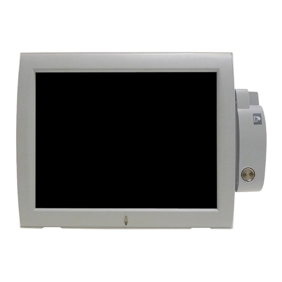
Page 10: System View
2. System View 2.1. Front View Optional MSR Module Touch Screen 2.2. Rear View Optional VFD Module VESA Mounting Holes Speakers Ventilation... -
Page 11: I/O View
2.3. I/O View PS/2 (for external device) DC - IN COM to PC PS/2 to PC USB to PC (for optional reader) Power Button Menu Button Left Button Right Button Select Button... -
Page 12: Drivers Installation
3. Drivers Installation 3.1. Driver List Folder/File File Description <CD>:\OLC15_Vesa\OLC15_Vesa.htm OLC 15 Driver List <CD>:\COMMON\Elo_Touch ELO Touch Driver <CD>:\COMMON\USB2COM\PL-2303HX USB Driver for VFD -The following procedures are for Windows 2000/XP, other platforms are similar. -
Page 13: Elo Touch Driver Installation
3.2. ELO Touch Driver Installation a. Click the “Elo_v481” on the b. Click “OK” button on the “Welcome to “Win98-ME_2X_XP_2003” window. ELO…” dialog box for WinZip Self-Extracting. c. Click “Unzip” Button on the “Winzip d. Click “OK” Button after it shows files Self Extractor –... - Page 14 g. Click “Yes” on the “Elo Touchscreen h. Click “Auto-detech Elo touchscreens” Setup” Dialog box. check box, then press “Next” Button. i. Choose “COM 5” on the list box then j. Click “Next” on the “ You have selected click “Next”. the COM ports listed….”...
- Page 15 m. To touch the “Target” starting from the n. Click the icon to complete the upper left corner one bye one for touchscreen calibration. touchscreen alignment. o. You can also double click the “Elo p. The “Elo Touchscreen Properties” dialog Touch Utility”...
-
Page 16: Usb Vfd Driver Installation
3.3. USB VFD Driver Installation a. Click the “PL-2303 Driver Installer” on b. Click the “Next” button on the the “Win98-ME_2X_XP_2003” Welcome window window c. Click the “Finish” button on the InstallShield window The driver will be installed on the first free COM port in the system. In general this will be COM7, but the actual number may be different, depending on your system configuration. -
Page 17: Peripheral Assembly And Disassembly
4. Peripheral Assembly and Disassembly 4.1. VFD Replacement a. Disconnect the VFD Cable (1) and remove the screws (2). b. Remove the VFD Module from the Rear Cover. -
Page 18: Optional Module Installation
4.2. Optional Module Installation This installation description applies to: Magnetic Card Reader, iButton Dallas key Reader, Magnetic Card + iButton Dallas key Reader, RFID Reader and Magnetic Card + Biometric (fingerprint) Reader. Note: for RFID Reader and Biometric (fingerprint) Reader installation, please first read the notes on next page a. - Page 19 Notes regarding the installation of a RFID Reader or a Biometric (Fingerprint) Reader The RFID Reader and the Biometric (fingerprint) Reader have a USB interface. If your OLC15 VESA is equipped with VFD Customer Display, which also uses a USB interface, you can not connect a RFID Reader or a Biometric (fingerprint) Reader, because they use the same USB port as the VFD Customer Display.
-
Page 20: System Disassembly
5. System Disassembly 5.1. Opening the Rear Cover To open the rear cover, if your system installed with VFD and MSR peripherals, please loose them first. See detail disassembly as below: a. Remove the MSR Module as described in Chapter 4.2. b. -
Page 21: Replacing The Scalar Board
5.2. Replacing the Scalar Board To replace the scalar board, please first follow the steps in chapter 5.1 and 5.2 a. Remove the hex nuts (4) on the I/O Metal Bracket. b. Disconnect the cables (8) c. Remove the screws (5) then slide out the scalar board to detach it from the I/O Metal Bracket. -
Page 22: Replacing The Inverter Board
5.3. Replacing the Inverter Board To replace the inverter board, please first follow the steps in chapter 5.1, 5.2, and 5.3. a. Disconnect the cables (3) b. Remove the screws (2) to replace the inverter board 5.4. Replacing the OSD Board To replace the OSD board, please first follow the steps in chapter 5.1, 5.2, and 5.3. -
Page 23: Specification
6. Specification Model Name OLC 15 VESA LCD Panel Panel Size 15" TFT LCD Brightness 250nits Resolution 1024 x 768 Touch Resistive Type (USB interface) Tilt Angle External I/O Ports PS/2 2 (1xIN, 1xOUT) OSD Button 5 (power, menu, left, right, select) 1 x USB 2.0 OUT, 1x USB 2.0 IN (B type) -
Page 24: Customer Display Software Commands
7. Customer Display Software Commands The default settings for the Customer Display are: • EPSON ESC/POS command set • 9600 Baud, 8 bits, no parity, no flow control Software Utilities The following software utilities are provided for the customer display on the driver CD Folder/File File Description <CD>:\Common\CustomerDisplay\Configuration... -
Page 25: Baud Rate Setting Command
Baud Rate Setting Command /Change the baud rate setting/ STX 05 B n ETX ASCII Format STX 05 B n ETX Dec. Format [02] [05] [66] n [03] Hex. Format [02h][05h][42h] n [03h] n=30h, 31h, 36h or 37h Description Change the display communication baud rate. The baud rate setting can be selected from 4800 to 38400. - Page 26 International Character Set Setting Command Character Set Code Table Note (20h – 7Fh) (80H-FFH) U.S.A. CP-437 (USA, Standard Europe) FRANCE GERMANY U.K. DENMARK I CP-858 (Multilingual + Euro Symbol) SWEDEN ITALY SPAIN JAPAN Katakana NORWAY CP-858 (Multilingual+ Euro Symbol) DENMARK II Slawie RUSSIA U.S.A.
-
Page 27: Select International Character Set Command
Select International Character Set Command /Select International Character Set Command/ STX 05 T n ETX ASCII Format STX 05 T n ETX Dec. Format [02] [05] [84] n [03] Hex. Format [02h][05h][54h] n [03h] 00h≦n≦1Fh Description Select International Character Set Select international character set (20H~7Fh) by command “STX 05 T n ETX”... - Page 28 Command Type Setting Command /Change the command type setting/ STX 05 C n ETX ASCII Format STX 05 C n ETX Dec. Format [02] [05] [67] n [03] Hex. Format [02h][05h][43h] n [03h] 30h≦ n≦37h Description This command will change the command type and initialize the display.
- Page 29 User Defined Character Command Set Function Command Description Delete one user defined character data. Del 1 Character [02h][FDh][55h][00h][n] [n] = 20h ~ FFh for displayable character codes Del All Characters [02h][FDh][55h][01h][00h] Delete All User-Define Characters Set one user defined character [n] = 20h ~ FFh [02h][FDh][55h][02h][n] Set 1 Character for displayable character codes/[m1]~[m5] =...
-
Page 30: Command List Table
Command List Table Command Set EPSON UTC/S UTC/P AEDEX Command 7300 5220 D101 Move cursor right Move cursor left Move cursor up Move cursor down Move cursor to right-most position Move cursor to left-most position Move cursor to home position Move cursor to bottom position Move cursor to specified position Clear display screen... - Page 31 Command Set EPSON UTC/S UTC/P AEDEX Command 7300 5220 D101 Clear upper line and move cursor to upper left-end position Clear bottom line and move cursor to bottom left-end position Set period to upper line, last n position Set line blinking, upper line Clear line blinking, upper line Clear field 1 and move cursor to field 1, first position...
-
Page 32: Command Details
Command Details POS7300 Series Command List Command Code (hex) Function Description ESC F A [DATA] Write string to upper line 1B 46 41 [DATA] 0D Maximal [DATA] length is 40 ESC F B [DATA] Write string to lower line 1B 46 42 [DATA] 0D Maximal [DATA] length is 40 ESC F D [DATA] Upper line message scroll continuously... - Page 33 Command Code (hex) Function Description NULL G 0 47 Move cursor to left-most position NULL O 0 4F Move cursor to right-most position Back space Horizontal tab Line feed Move cursor to home position US B 1F 42 Move cursor to bottom position Clear display screen Carriage return Clear cursor line, and clear string mode...
-
Page 34: Cd5220 Standard Mode Command List
CD5220 Standard Mode Command List Command Code (hex) Function Description ESC DC1 1B 11 Overwrite mode US SOH 1F 01 ESC DC2 1B 12 Vertical scroll mode US STX 1F 02 ESC DC3 1B 13 Horizontal scroll mode US ETX 1F 03 Set the string display mode, write string to ESC Q A [DATA]... - Page 35 Command Code (hex) Function Description Set or cancel the window range at horizontal scroll mode 1 ≦ x1 ≦ x2 ≦ 14h, for columns ESC W s x1 x2 y 1B 57 s x1 x2 y location. y = 1~2, for lines location. s = 0: cancel s = 1: set Clear display screen, and clear string mode...
-
Page 36: Utc Standard Mode Command List
4. Select character code table (80H-FFH) by command “ESC c n”. Parameter “n” character Code Table Character ‘A’ Compliance with ASCII code (CP-437) ‘J’ Compliance with JIS code (Katakana) ‘L’ Compliance with Slawie code ‘R’ Compliance with RUSSIA code ‘M’ CP-850 (Multilingual) ‘P’... -
Page 37: Utc Enhanced Mode Command List
UTC Enhanced Mode Command List Command Code (hex) Function Description ESC u A Upper line display 1B 75 41 [DATA] 0D [DATA] CR Maximal [DATA] length is 20 ESC u B Bottom line display 1B 75 42 [DATA] 0D [DATA] CR Maximal [DATA] length is 20 ESC u D Upper line message scroll continuously... -
Page 38: Dsp800 Mode Command List
DSP800 Mode Command List Command Code (hex) Function Description EOT SOH I n Select international character set 04 01 49 n 17 n = 00 ~ 1Fh or 30 ~ 4Fh See note * EOT SOH P n Move cursor to specified position 04 01 50 n 17 n = 31h ~ 58h EOT SOH C n... - Page 39 EPSON ESC/POS Command List Command Code (hex) Function Description Select/cancel reverse character. US r n 1F 72 n n = 00,01 US MD1 1F 01 Specify overwrite mode. US MD2 1F 02 Specify vertical scroll mode. US MD3 1F 03 Specify horizontal scroll mode.
- Page 40 Command Code (hex) Function Description Set or cancel the window range n = 1 ~ 4, for window number ESC W n s x1 1B 57 n s x1 y1 x2 s = 0: cancel s = 1: set y1 x2 y2 1 ≦...
- Page 41 Character Set Character Codes 20H – 7FH International Character Sets Character Code Number Hex 23 Country Dec 35 ¦ U.S.A à ° ç § é ù è ¨ France § Ä Ö Ü ä ö ü β Germany £ ¦ Æ...
- Page 42 Character Codes 80H – FFH CP-437 (USA, Standard Europe) 00h 01h 02h 03h 04h 05h 06h 07h 08h 09h 0Ah 0Bh 0Ch 0Dh 0Eh 0Fh Ç ü é â ä à å ç ê ë è ï î ì Ä Å...
- Page 43 Katakana for Japan 00h 01h 02h 03h 04h 05h 06h 07h 08h 09h 0Ah 0Bh 0Ch 0Dh 0Eh 0Fh α β є η θ λ µ π ρ σ Ф γ τ ⊿ £ § ² ³ ½ ± √ 。...
- Page 44 CP-860 (Portuguese) 00h 01h 02h 03h 04h 05h 06h 07h 08h 09h 0Ah 0Bh 0Ch 0Dh 0Eh 0Fh Ç ü é â ã à Á ç ê Ê è Í Ô ì Ã Â É À È ô õ ò Ú...
- Page 45 CP-862 (Hebrew) 00h 01h 02h 03h 04h 05h 06h 07h 08h 09h 0Ah 0Bh 0Ch 0Dh 0Eh 0Fh ¢ £ ¥ ƒ ₧ á í ó ú ñ Ñ ª º ¿ ¬ ½ ¼ ¡ « » ß µ ±...
- Page 46 CP-866 (Cyrillic) 00h 01h 02h 03h 04h 05h 06h 07h 08h 09h 0Ah 0Bh 0Ch 0Dh 0Eh 0Fh И э ° · ¤ Ё ё Є Ї ї Ў ў · № Windows-1250 00h 01h 02h 03h 04h 05h 06h 07h 08h 09h 0Ah 0Bh 0Ch 0Dh 0Eh 0Fh ‚...
- Page 47 Windows-1252 00h 01h 02h 03h 04h 05h 06h 07h 08h 09h 0Ah 0Bh 0Ch 0Dh 0Eh 0Fh ‚ ƒ „ … † ‡ ˆ ‰ Š ‹ Œ Ž ‘ ’ “ ” • – — ˜ ™ š › œ...
- Page 48 Windows-1257 (Baltic) 00h 01h 02h 03h 04h 05h 06h 07h 08h 09h 0Ah 0Bh 0Ch 0Dh 0Eh 0Fh ‚ „ … † ‡ ‰ ‹ ¨ ˇ ¸ ‘ ’ “ ” • – — ™ › ¯ ˛ ¢ £...
- Page 49 Command Details A.1. Overwrite mode In this mode, the cursor will move towards the right and begin from the upper left position. When the cursor has reached the end of the upper line, the cursor will move down to the bottom left position to continue.
- Page 50 A.7. Move cursor right Move the cursor to the right. When the cursor has reached the right-end, this command operates differently depending on the display mode. Overwrite mode: When the cursor has reached the right-end of the lower line, it will continue to the left-end of the upper line and overwrite previous characters.
- Page 51 The cursor will be moved to column x on line y. A.15. Initialize display The data in the input buffer will be cleared and reset from default. A.16. Reset the window Reset the window on the display. When s=0, the window is cancelled (values: x1, x2, and y are not required.) When s=1, the window will be reset (values: x1, x2, and y are required.) The x1 and x2 set the position of the left column and right column, respectively, of the window.
- Page 52 Control Code Set CODE CODE NULL SOH, MD1 STX, MD2 ETX, MD3 EOT, MD4 ENQ, MD5 ACK, MD6 BEL, MD7 BS, MD8 VT, HOM FF, CLR SO, SLE1 RS, SF1 SI, SLE2 US, SF2...
-
Page 53: Olc 15 Vesa Dimensions
8. OLC 15 VESA dimensions...
Need help?
Do you have a question about the OLC 15 and is the answer not in the manual?
Questions and answers