Advertisement
Quick Links
How To Order Replacement Parts
If you encounter any difficulties with this product or if you need to order replacement parts, please call or write
the ICON Health & Fitness, Ltd. office.
ICON Health & Fitness, Ltd.
Greenwich House
223 North Street
Sheepscar
Leeds LS7 2AA
West Yorkshire
Tel: Country Code:
0345-089009
Fax: 0113-2411120
When calling or writing, please provide the following information:
1. The MODEL NUMBER of the product (WLEMSY82000)
2. The NAME of the product (WESLO
®
GYM 4000)
3. The SERIAL NUMBER of the product (see the front cover of this manual)
4. The KEY NUMBER and DESCRIPTION of the part(s) (see the PART LIST and EXPLODED DRAWING
attached in the centre of this manual).
Part No. 171109 R1000A
Printed in Canada © 2000 ICON Health & Fitness, Inc.
Model No. WLEMSY82000
Serial No.
Write the serial number in the space
above for reference.
Serial Number Decal
QUESTIONS?
As a manufacturer, we are com-
mitted to complete customer sat-
isfaction. If you have questions,
or if there are missing/damaged
parts, we will guarantee you com-
plete satisfaction through direct
assistance from our factory.
Please CALL:
0345-089009
Or WRITE:
ICON Fitness Lifestyle Ltd.
Greenwich House
223 North Street
Sheepscar
West Yorkshire
Leeds LS7 2AA
CAUTION
Read all precautions and instruc-
tions in this manual before using
this equipment. Save this manual
for future reference.
USER'S MANUAL
Visit our website at
www.weslo.com
new products, prizes,
fitness tips, and much more!
Advertisement

Related Manuals for Weslo gym4000


Summary of Contents for Weslo gym4000
- Page 1 Fax: 0113-2411120 When calling or writing, please provide the following information: 1. The MODEL NUMBER of the product (WLEMSY82000) Serial Number Decal 2. The NAME of the product (WESLO ® GYM 4000) QUESTIONS? 3. The SERIAL NUMBER of the product (see the front cover of this manual) 4.
- Page 2 Note: An EXPLODED DRAWING/PART LIST and a PART IDENTIFICATION CHART are attached in the centre of this manual. Remove the EXPLODED DRAWING/PART LIST and the PART IDENTIFICATION CHART before 1—High Pulley beginning assembly. 7—Long “U”-Bracket Short Cable (58) Weight Stack—8 1—Low Pulley WESLO is a registered trademark of ICON Health & Fitness, Inc.
- Page 3 Trouble-shooting and Maintenance Important Precautions Inspect and tighten all parts each time you use the home gym system. Replace any worn parts immediately. The WARNING: home gym system can be cleaned using a damp cloth and mild non-abrasive detergent. Do not use solvents. To reduce the risk of serious injury, read the following important precautions before using the home gym system.
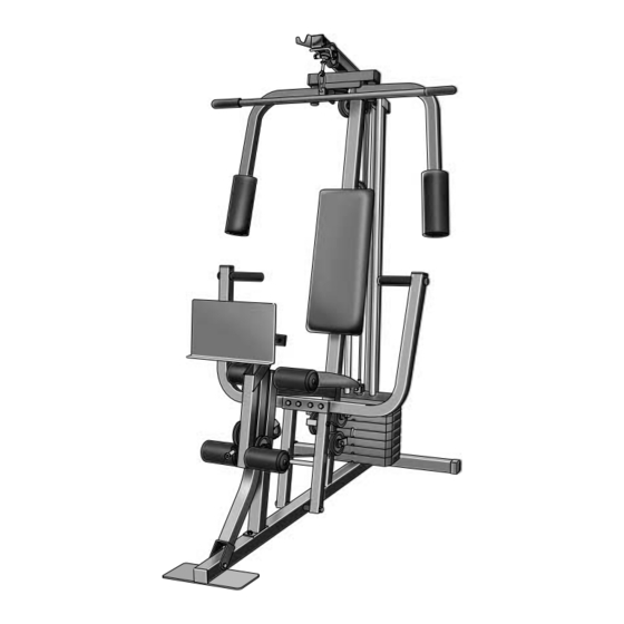
- Page 4 ADJUSTING AND REMOVING THE LEG PRESS Before You Begin PLATE AND ADJUSTMENT TUBE To adjust the position of the Leg Press Plate (78), Thank you for selecting the versatile WESLO ® questions, please call our Customer Service remove the “L”-Pin (40) from the Press Adjustment 4000 home gym system.
- Page 5 Adjustment Assembly The instructions below describe how each part of the home gym system can be adjusted. IMPORTANT: When attaching the lat bar or nylon strap, make sure that the attachments are in the correct starting position Before beginning assembly, carefully read the •...
- Page 6 2. Slide the Front Upright (42) onto the 5/16” x 32. Press a 1 3/4” Square Inner Cap (44) into the 2 1/2” Carriage Bolts (1) in the Base (4). Press Adjustment Tube (79). Hand tighten a 5/16” Nylon Locknut (3) onto each Carriage Bolt.
- Page 7 29. Attach the Long Cable (23) to the Small “U”- 5. Press the Weight Tube Bumper (64) into the Bracket (67) with a 1/4” Nylon Locknut (2) end of the Weight Tube (63). Insert the Holes and a 1/4” Flat Washer (10). Do not com- Weight Tube into the stack of Weights (25).
- Page 8 8. Press a 1 3/4” Square Inner Cap (44) into the 26. Note: The 3 1/2” Pulley (15) labelled in this top of a Press Arm (46). Wet the handle on step is pre-attached. It is shown removed the Press Arm with soapy water. Slide a for easy part identification.
- Page 9 22. Locate the Short Cable (58). Route the 11. Press a 1 3/4” Square Inner Cap (44) into the Short Cable under the 3 1/2” Low Pulley (77). Seat Frame (36). Attach a Bumper (73) to the Bracket Be sure that the end of the Cable with the Seat Frame with a 1/2”...
- Page 10 14. During steps 15 through 29, refer to the 18. Route the Long Cable (23) around the “V”- CABLE DIAGRAM on page 19 of this manual Pulley (6) on the Right Arm (48). Be sure to verify proper cable routing. Before begin- that the Cable is in the groove of the “V”- ning this section, identify the Long Cable (23) Pulley and that the Long Cable Trap (50) is...
- Page 11 REMOVE THIS PART IDENTIFICATION CHART FROM THE MANUAL 1/2" x 3/4" Spacer (61) 3/4" Round Inner Cap (34) 1" x 7/8" Plastic Bushing (75) This chart is provided to help you identify the small parts used in assembly. Important: Some parts may have been pre-assembled for shipping purposes.
- Page 12 1/4" Nylon Locknut (2) 5/16" Nylon Locknut (3) 1/4" Flat Washer (10) 5/16" x 1 3/4" Bolt (72) 3/8" Nylon Locknut (21) 5/16" Flat Washer (8) 5/16" x 2 1/2" Bolt (22) 3/8" Nylon Jam Nut (33) 5/16" x 2 3/4" Bolt (11) 3/8"...
- Page 13 Part List—Model No. WLEMSY82000 R1000A REMOVE THIS PART LIST/EXPLODED Key No. Qty. Description Key No. Qty. Description DRAWING FROM THE MANUAL. SAVE 5/16” x 2 1/2” Carriage Bolt 1/4” x 2 1/2” Screw 1/4” Nylon Locknut 1 3/4” Square Inner Cap THE PART LIST/EXPLODED DRAWING 5/16”...
- Page 14 Exploded Drawing—Model No. WLEMSY82000 R1000A 66 16...
Need help?
Do you have a question about the gym4000 and is the answer not in the manual?
Questions and answers