Table of Contents
Advertisement
Operator's Manual
Mid-Engine Rider
13.5 HP. Electric Start
30" Mower / Mulcher
Hydrostatic Drive
Model 536.270321
CAUTION: Before using this
product, read this manual
and follow all of its Safety
Rules and Operating
Instructions.
Manual del usario
(página 65)
Tractor cortacésped con motor
situado detrás del asiento
Arranque eléctrico de 13,5 caballos
Cortacésped / trituradora de 76 cm.
Transmisión hidrostática
Modelo 536.270321
PRECAUCIÓN: Antes de usar este
producto, lea este manual y siga
todas las reglas de seguridad e
instrucciones de operación.
Sears, Roebuck and Co., Hoffman Estates, IL. 60179 U.S.A.
400150 11/08
Rev. 09-020
www.sears.com/craftsman
Safety
Operation
Maintenance
Parts
Seguridad
Operación
Mantenimiento
Piezas
Advertisement
Chapters
Table of Contents

Related Manuals for Craftsman 536.270321


Summary of Contents for Craftsman 536.270321
- Page 1 Operation Mid-Engine Rider Maintenance Parts 13.5 HP. Electric Start 30” Mower / Mulcher Hydrostatic Drive Model 536.270321 CAUTION: Before using this product, read this manual and follow all of its Safety Rules and Operating Instructions. Manual del usario (página 65) Tractor cortacésped con motor...
-
Page 2: Table Of Contents
30 days of purchase, there will be no charges to replace the battery at your home. After the first 30 days, for your conve- nience, IN-HOME warranty service will still be available but a trip charge will apply. This charge will be waived if the Craftsman product is dropped off at an authorized Sears location. -
Page 3: Product Specifications
Congratulations on your purchase of a Craftsman Mid-Engine Rider. It has been designed, engineered and manufactured to Craftsman Mid-Engine Rider give you the best possible dependability and performance. Record in the space below the serial number and the date If you experience any problems you cannot easily remedy, please of purchase of this unit. -
Page 4: Safety Rules
SAFETY RULES Safe Operation Practices for Ride−on Mowers The safety symbol is used to identify safety information about hazards that can result in personal injury. A signal word (DAN- GER, WARNING, or CAUTION) is used with the alert symbol to indicate the likelihood and the potential severity of injury. In addition, a hazard symbol may be used to represent the type of hazard. - Page 5 SAFETY RULES III. Children Use only an approved container. Never remove the gas cap or add fuel with the engine run- Tragic accidents can occur if the operator is not alert to the presence ning. Allow the engine to cool for several minutes before of children.
-
Page 6: International Pictorials
SAFETY RULES INTERNATIONAL PICTORIALS IMPORTANT: Some of the following pic- Flush Eyes Immediately With Water. 10 DANGER: No Step. torials are located on your unit or on Get Medical Help Fast. 11 DANGER: Keep Feet And Hands literature supplied with the product. Be- Away From Rotating Blade. -
Page 7: Preparation
PREPARATION PREPARATION Locate the two tear tabs at the top of the carton. Pull the tear tape no more than twelve inches at a time. Read and follow the preparation instructions for your mower. All fasteners are in the parts bag. Do not discard any parts or material Re-grasp the tear tape next to the carton and pull again. -
Page 8: Maintenance Free Battery
PREPARATION MAINTENANCE FREE BATTERY Remove the protective cap from the battery terminal. Use a 12 volt battery charger to charge the battery. Charge at IMPORTANT: Before you attach the battery cables to the a rate of 6 amperes for one hour. If you do not have a battery battery, check the battery date. -
Page 9: How To Engage The Transmission
PREPARATION HOW TO ENGAGE THE TRANSMISSION To allow the unit to be pushed, the unit was shipped with the automatic drive disconnect in the PUSH POSITION. Before operating, the automatic drive disconnect must be set in the DRIVE POSITION. (Figure 2) Automatic Drive Disconnect The engine must be off. -
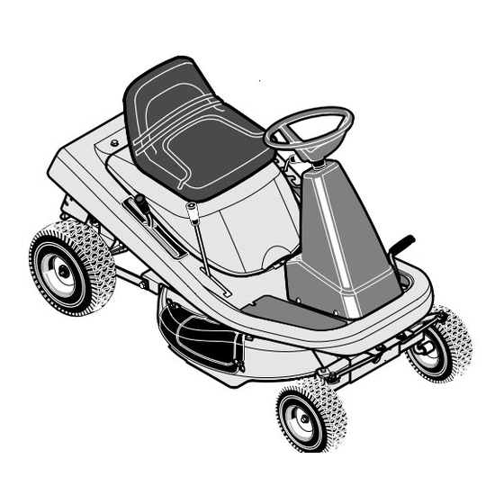
Page 10: Operation
OPERATION Ignition Key Switch Clutch / Brake Pedal Attachment Clutch Speed Control Lever Lift Lever Throttle Control Lever Figure 3 The operation of any lawn mower can result in foreign objects thrown in the eyes, which can result in severe eye damage. -
Page 11: How To Operate The Ignition Key Switch
OPERATION ATTACHMENTS This unit can use many different attachments. See the attachment weight is 200 pounds. Gross weight is the weight of the attachment page in this book. This unit can pull attachments like a lawn or trailer and any load that might be on or in it. sweeper, a lawn aerator, a hopper spreader, or a small trailer. -
Page 12: How To Stop The Unit
OPERATION HOW TO STOP THE UNIT Completely push the clutch/brake pedal forward to stop the WARNING: Make sure the parking brake will hold the unit. Keep your foot on the pedal. unit. Move the throttle control to the SLOW position. Move the attachment clutch to the DISENGAGE position. -
Page 13: How To Change The Cutting Height
OPERATION HOW TO USE THE ATTACHMENT CLUTCH Use the attachment clutch to engage the blade (Figure 7). Before you start the engine, make sure the attachment clutch is in the DISENGAGE position. Disengage To rotate the blade, move the attachment clutch forward to Position lock the blade in the ENGAGE position. -
Page 14: How To Disconnect The Transmission
OPERATION HOW TO DISCONNECT THE TRANSMISSION To push the unit, use the automatic drive disconnect to release the transmission. (Figure 9) The engine must be off. The automatic drive disconnect is located under the left side of the seat deck next to the hydrostatic transaxle. Automatic Drive Disconnect To release the transmission and push the unit, pull and twist the DRIVE POSITION... - Page 15 OPERATION HOW TO USE THE SPEED CONTROL LEVER The Hydrostatic Drive is very easy to operate. The drive system has a a clutch/brake pedal on the left side (see Figure 10) and a speed Clutch/Brake control lever on the right side (see Figure 11). Pedal The speed and direction of travel is controlled by the speed control lever (see Figure 11).
-
Page 16: How To Transport The Unit
OPERATION SPEED CONTROL LEVER POSITIONS FUNCTION THROTTLE SPEED The forward speed is controlled by the position of the speed control CONTROL lever. The following chart provides functions along with the LEVER positions of the speed control lever. Always operate the engine POSITION with the throttle control in the FAST position. -
Page 17: How To Install The Side Discharge Attachment
OPERATION HOW TO INSTALL THE SIDE DISCHARGE ATTACHMENT Remove the fasteners that secure the mulcher cover (see WARNING: To prevent the engine from starting, dis- connect the wire from the spark plug. Make sure the Figure 15). attachment clutch is in the DISENGAGE position. Lift the mulcher cover. - Page 18 OPERATION BEFORE STARTING THE ENGINE Clean the area around the dipstick. Remove the dipstick. Wipe the oil from the dipstick. CHECK THE OIL Insert the dipstick into the oil fill tube. Turn the dipstick clock- wise until it is tight. Remove the dipstick. Check the oil level on NOTE: The engine was shipped from the factory filled with oil the dipstick.
-
Page 19: How To Start The Engine
OPERATION CARBURETOR The factory settings for the carburetor are for most conditions. If the A change from summer to winter operation. engine is operated under the following conditions, the carburetor A 40 degree change in the operation temperature. The carbure- may require an adjustment. -
Page 20: How To Operate The Unit On Hills
OPERATION HOW TO OPERATE WITH THE MOWER HOUSING WARNING: The mulch cover is a safety device. Do not CAUTION: Do not operate with the mower housing in the LEVEL ADJUSTMENT position. If you operate in the remove the mulch cover. The side discharge attach- LEVEL ADJUSTMENT position, the mower housing and ment forces the discharged material toward the blades can be damaged. -
Page 21: Operating Tips
OPERATION OPERATING TIPS Check the attachment clutch for correct adjustment. For the Before you make an inspection, adjustment (except for the car- blade(s) to disengage correctly, the adjustment must be cor- buretor) or repair, make sure the wire from the spark plug is dis- rect. -
Page 22: Maintenance
MAINTENANCE MAINTENANCE TABLE FIRST EVERY EVERY EVERY EVERY EACH BEFORE STORAGE PROCEDURE HOURS HOURS HOURS HOURS HOURS Tires, Check √ Blade, Inspect and Sharpen √ Battery, Check and Charge √ √ Battery, Clean √ √ √ √ Lubrication √ √ Oil, Check Oil, Change √... -
Page 23: How To Remove And Install The Blade
MAINTENANCE INSPECT BLADE Tighten the nut that holds the blade to a torque of 35 foot pounds. WARNING: Before you inspect or remove the blade, disconnect the wire to the spark plug. If the blade Install the mower housing. See “How To Install The Mower hits an object, stop the engine. - Page 24 MAINTENANCE MAINTENANCE FREE BATTERY HOW TO REMOVE THE BATTERY Clean the terminals and the ends of the cables with a wire brush. To charge or clean the battery, remove the battery from the unit as Install the battery. follows. To prevent corrosion, apply grease to the battery terminals. WARNING: To prevent sparks, disconnect the black battery cable from the negative (−) terminal before you HOW TO CHARGE THE BATTERY...
-
Page 25: Where To Lubricate
MAINTENANCE WHERE TO LUBRICATE Apply grease with a brush to the areas shown. Lubricate the areas shown with engine oil. NOTE: Apply grease to the steering gear assembly. CAUTION: If the unit is operated in dry areas that have sand, use a dry graphite spray to lubricate the unit. -
Page 26: How To Check The Oil
MAINTENANCE ENGINE Remove the oil drain plug. Drain the oil completely from the engine. Install and tighten the oil drain plug. Only use a high quality detergent oil rated with API service HOW TO CHECK THE OIL classification SG, SH, SJ or SL. Select the oil’s SAE viscosity grade according to the expected operating temperature using NOTE: Do not check the level of the oil while the engine runs. -
Page 27: How To Check The Spark Plug
MAINTENANCE HOW TO SERVICE THE AIR FILTER Cartridge removal / installation Pull up on the handle for the air cleaner cover. Rotate the han- dle toward the engine (Figure 25). NOTE: Never run the engine with the air filters (air cleaner cartridge, pre-cleaner) removed. -
Page 28: Service And Adjustment
SERVICE AND ADJUSTMENT HOW TO LEVEL THE MOWER HOUSING If the mower housing is level, the blade will cut easier and the lawn will look better. Level Adjustment WARNING: Before you make an inspection, adjust- Position ment, or repair to the unit, disconnect the wire to the Lift Lever spark plug. - Page 29 SERVICE AND ADJUSTMENT Check the blade(s). Keep a sharp edge on the blade(s). A blade HOW TO ADJUST THE ATTACHMENT CLUTCH that is not sharp will cause the tips of the grass to become WARNING: To prevent an injury, the attachment brown.
-
Page 30: How To Remove The Mower Housing
SERVICE AND ADJUSTMENT HOW TO REMOVE THE MOWER HOUSING HOW TO INSTALL THE MOWER HOUSING Move the attachment clutch to the DISENGAGE position. Push the mower housing under the right side of the unit. Move the lift lever to the level adjustment position (Figure 32). Put the mower drive belt around the stack pulley. -
Page 31: How To Replace The Motion Drive Belts
SERVICE AND ADJUSTMENT HOW TO REPLACE THE MOTION DRIVE BELTS ENGINE DRIVE BELT REMOVAL Remove the mower housing. See the instructions on “How To Remove The Mower Housing”. Set the rear hitch on a 10 to 12 inch block. The block must be high enough to raise the rear wheel of off the ground (see Figure 34). -
Page 32: How To Replace The Mower Drive Belt
SERVICE AND ADJUSTMENT HOW TO REPLACE THE MOWER DRIVE BELT Remove the mower housing. See the instructions on “How To Pull the belt retainer away from the idler pulley. Put the mow- Remove The Mower Housing”. er drive belt around the idler pulley. Pull the belt retainer away from the idler pulley and remove the mower drive belt (Figure 39). -
Page 33: How To Check And Adjust The Clutch
SERVICE AND ADJUSTMENT HOW TO ADJUST THE SPEED CONTROL LEVER WARNING: Before you make an inspection, adjust- Assemble the adjuster nut to the hydro actuator arm and ment, or repair to the unit, disconnect the wire to the secure with the hair pin. spark plug. -
Page 34: How To Install The Wheels
SERVICE AND ADJUSTMENT HOW TO INSTALL THE WHEELS Cotter Pin If the wheels must be removed for service, make sure they are Hub Cap installed as follows. Washer Washer Front Wheel Make sure the valve stem is to the outside of the tractor. Slide the front wheel on the spindle (See Figure 42). -
Page 35: How To Replace The Fuse
SERVICE AND ADJUSTMENT HOW TO REPLACE THE FUSE THE ENGINE If the fuse is blown, the engine will not start. The location of the fuse Clean the dirt and grass from the engine. is next to the battery. Remove the fuse and replace with a 15 amp. automotive fuse (Figure 44). -
Page 36: Troubleshooting Chart
TROUBLESHOOTING CHART PROBLEM: The engine will not start. PROBLEM: Excessive vibration. Follow the steps, “How To Start The Engine” in this book. Replace the blade. Check for loose engine bolts. Electric−Start Models: Clean the battery terminals. Tighten the cables. Decrease the air pressure in the tires. Drain the fuel tank. - Page 37 Sears, Roebuck and Co., USA (Sears), the California Air Resources Board (CARB) and the United States Environmental Protection Agency (U.S. EPA) Emissions Control System Warranty Statement (Owner’s Defect Warranty Rights and Obligations) The California Air Resources Board (CARB), U.S. EPA and Sears provided there has been no abuse, neglect or improper mainte- are pleased to explain the Emissions Control System Warranty on nance of your small off-road engine.
- Page 38 Look For Relevant Emission Durability Period and Air Index Information OnYour Engine Emission Label Engines that are certified to meet the California Air Resources Board (CARB) Tier 2 Emission Standards must display information regarding the Emissions Durability Period and the Air Index. Briggs &...
-
Page 39: Slope Guide
400150... -
Page 40: Repair Parts
MODEL 536.270321 REPAIR PARTS CHASSIS & HOOD 400150... - Page 41 MODEL 536.270321 REPAIR PARTS CHASSIS & HOOD Part No. Description Part No. Description 690566 Seat 1401282 Spring, Seat Deck 1401379E701 Hood 1401352E701 Bracket, Prop Rod 017x47 Washer 26x201 Screw 1001054 Bolt, Wing 15x116 Nut, NY−Lock 002x16 Bolt, Carriage 1401248 Control, Throttle...
- Page 42 MODEL 536.270321 REPAIR PARTS STEERING 400150...
- Page 43 MODEL 536.270321 REPAIR PARTS STEERING Part No. Description Part No. Description 1001980 Wheel, Steering 011x23 E−Ring, Retainer 1001982 Cover, Steering Wheel 030x35 Pin, Cotter 1401067 Console, High (Black) 094131 Retainer, Spring 26x250 Screw 1401046E701 Rack, Steering 1401090 Bearing, Upper Steering...
- Page 44 MODEL 536.270321 REPAIR PARTS MOTION DRIVE 400150...
- Page 45 Model 536.270321 REPAIR PARTS MOTION DRIVE Part No. Description Part No. Description ------------ Engine 094497 Grip 1401380 Engine Plenum* 1401148 Nut, Adjusting 091309 Gasket, Muffler 1401383 Lever, Shift 1401358 Muffler 1401340E701 Bracket, Pivot 092378 Lock, Muffler Screw 165x147 Spring, Variator Drive...
-
Page 46: Mower Housing Suspension
MODEL 536.270321 REPAIR PARTS MOWER HOUSING SUSPENSION 400150... - Page 47 MODEL 536.270321 REPAIR PARTS MOWER HOUSING SUSPENSION Part No. Description Part No. Description 094497 Grip, Lift Lever 17x206 Washer 1401117 Lever, Lift 015x79 Nut, Flange 165x154 Spring, Extension 015x84 Nut, Flange 094137 Pad, Friction 1401147 Spring, Leaf 017x45 Washer 1401040E701 Hanger, Front...
- Page 48 MODEL 536.270321 REPAIR PARTS MOWER HOUSING 400150...
- Page 49 MODEL 536.270321 REPAIR PARTS MOWER HOUSING Part No. Description Part No. Description 37x111 Belt, Blade Drive 030x20 Pin, Cotter 1401092 Pulley, Input 1401185E701 Arm Assembly, Brake 15x140 Locknut 1401119 Link, Idler Arm 015x98 Nut, Flange 0025x7 Bolt 1401252 Pulley, Idler...
- Page 50 MODEL 536.270321 REPAIR PARTS ELECTRICAL SYSTEM 400150...
-
Page 51: Electrical System
MODEL 536.270321 REPAIR PARTS ELECTRICAL SYSTEM Part No. Description 250x146 Harness, Chassis Wire 1001995 Switch, Ignition 327349 Key, Ignition 094136 Switch, Limit (PTO) 302031 Fuse 407078 Holder, Fuse 1002004 Solenoid 26x229 Screw, Mounting 15x116 Locknut 24x37 Cable, Battery Ground 26x229... - Page 52 Clutch / Brake ( Footrest −Left Side) − − 48x5707 Cut Finger (Mower Deck −Right Side) − − 48x5915 Craftsman 13.5 (Hood −Right Side) − − 48x5916 Craftsman 13.5 (Hood −Left Side) − − 44x5214 Deck Level Position / ONLY (Seat Deck −Left Side) −...
- Page 53 400150...
- Page 54 BRIGGS & STRATTON ENGINE REPAIR PARTS MODEL 21B807-0326-E1 1264 1263 1270 400150...
- Page 55 BRIGGS & STRATTON ENGINE REPAIR PARTS MODEL 21B807-0326-E1 REF. PART REF. PART REF. PART DESCRIPTION DESCRIPTION DESCRIPTION 697377 Cylinder Assembly 792305 Piston Assembly 691003 Screw 399265 Kit−Bushing/Seal (Standard) (Cylinder Shield) (Magneto Side) −−−−−−− Note −−−−− 699908 Dipstick 3 K391086s Seal−Oil 792642 Piston Assembly K691032 Seal−Dipstick Tube (Magneto Side)
- Page 56 BRIGGS & STRATTON ENGINE REPAIR PARTS MODEL 21B807-0326-E1 1026 1022 1034 1029 1022 1023 358 ENGINE GASKET SET 1022 1095 VALVE GASKET SET 1266 1022 1266A 400150...
- Page 57 BRIGGS & STRATTON ENGINE REPAIR PARTS MODEL 21B807-0326-E1 REF. PART REF. PART REF. PART DESCRIPTION DESCRIPTION DESCRIPTION 3 K391086s Seal−Oil 690227 Stud K691031 Seal−O Ring (Magneto Side) (Carburetor) (Dipstick Tube) 697396 Head−Cylinder 691148 Screw 868 ∅K690968 Seal−Valve (Intake Manifold) 7∅K273280s Gasket−Cylinder Head K692236 Gasket−Exhaust 691986 Adjuster−Rocker Arm K697109 Gasket−Breather...
- Page 58 BRIGGS & STRATTON ENGINE REPAIR PARTS MODEL 21B807-0326-E1 1091 1127 121 CARBURETOR OVERHAUL KIT 1266 1266A 977 CARBURETOR GASKET SET 400150...
- Page 59 BRIGGS & STRATTON ENGINE REPAIR PARTS MODEL 21B807-0326-E1 REF. PART REF. PART REF. PART DESCRIPTION DESCRIPTION DESCRIPTION 51∅DK 692137 Gasket−Intake 791805 Line−Fuel 691119 Bolt 695425 Kit−Idle Mixture (Formed) (Governor Control Lever) 95 D690718 Screw 691693 Screw 791850 Clamp−Hose (Control Bracket) 691620 Pin−Cotter (Throttle Valve) 691841 Link−Mechanical...
- Page 60 BRIGGS & STRATTON ENGINE REPAIR PARTS MODEL 21B807-0326-E1 1036 EMISSION LABEL 1040 1044 305A 1070 1267 1005 1051 1266A 1266 1119 1051 1090 400150...
- Page 61 BRIGGS & STRATTON ENGINE REPAIR PARTS MODEL 21B807-0326-E1 REF. PART REF. PART REF. PART DESCRIPTION DESCRIPTION DESCRIPTION 792497 Flywheel 696459 Alternator 691237 Harness−Alterenator 697352 Guard−Flywheel 693699 Drive−Starter 697292 Filter−Pre Cleaner 697133 Screen−Rotating 692024 Clutch−Drive 697420 Cover−Air Cleaner 697897 Screw 692034 Armature−Starter 1005 699044 Fan−Flywheel (Rotating Screen)
- Page 64 INDEX Starting, 19 Mulcher, Operation, 21 Storage, 35 Mulcher Cover, Remove, 17 Throttle Control, 12 Adjustments Blade Drive Lever, 29 Clutch, 33 Mower Housing, Level, 28 Filter, Air, 27 Change, 26 Air Screen, 26 Check, 18, 26 Fuel, Type, 18 Attachments, 11 Type, 18 Fuse, 35...
-
Page 65: Garantía
Para su conveniencia, el servicio de garantía A DOMICILIO estará disponible todavía después de los primeros 30 días de la fecha de compra, pero se aplicará a este servicio un cargo por el viaje. Este cargo no será aplicado si lleva el Craftsman producto a un Centro de Servicio Sears autorizado. -
Page 66: Especificaciones Del Producto
Felicidades por su compra de este Tractor cortacésped con barométrica, humedad, combustible, lubricación del motor, máxi- motor situado detrás del asiento de Craftsman. Su unidad ha sido ma velocidad regulada del motor, el motor particular a la variabili- diseñada y fabricada para darle los mejores resultados en lo que dad del motor, diseño de la parte en particular del equipo... - Page 67 NOTA: Esta unidad está equipada con un motor de combustión bujía de resistencia para controlar las señales de encendido. interna y no debe ser utilizada sobre o cerca de terrenos no Consulte en un Centro de Servicio Sears para conseguir la bujía cultivados cubiertos de bosque, maleza o césped a menos que el de resistencia para el motor.
-
Page 68: Reglas De Seguridad
REGLAS DE SEGURIDAD Prácticas de operación segura para vehículos autoportados Se usa el símbolo de seguridad para identificar información de seguridad acerca de peligros que pudieran re- sultar en lesiones personales. Se usa una palabra de aviso (PELIGRO, ADVERTENCIA o PRECAUCIÓN) con el símbolo de alerta para indicar la posibilidad y la posible gravedad de una lesión. - Page 69 REGLAS DE SEGURIDAD RECOMENDACIONES IV. REMOLQUES En las cuestas, corte el césped verticalmente (hacia arriba y Puede usar el remolque sólo si la máquina tiene un gancho hacia abajo), y no en línea perpendicular (de lado a lado). diseñado para remolques. No remolque ningún equipo que no se pueda conectar al punto de enganche.
- Page 70 REGLAS DE SEGURIDAD tengan luces pilotos, calentadores, u otra fuentes de ignición. Nunca realice ajustes o reparaciones con el motor en mar- d. Nunca guarde el cortacésped con combustible en el tan- cha. El carburador puede ser ajustado mientras el motor que, o el recipiente de combustible en un recinto donde haya está...
- Page 71 REGLAS DE SEGURIDAD SIMBOLOS INTERNACIONALES IMPORTANTE: Los siguientes símbolos El ácido sulfúrico puede causar ceguera o PELIGRO: No pisar. quemaduras graves. están ubicados en su unidad o indica- PELIGRO: Mantenga los pies y las manos Limpie los ojos inmediatamente con agua. dos en la información impresa que está...
-
Page 72: Preparación
PREPARACIÓN PREPARACIÓN Ubique las dos lengüetas de separación ubicadas en la parte superior de la caja de cartón. Lea y siga las instrucciones de preparación para su cortacésped. Jale la cinta de separación por más de doce pulgadas a la vez. Todos los sujetadores se encuentran en la bolsa de piezas. - Page 73 PREPARACIÓN BATERÍA LIBRE DE MANTENIMIENTO Use un cargador de baterías de 12 voltios para cargar la batería. Cárguela a una velocidad de 6 amperios por hora. Si IMPORTANTE. Antes de conectar los cables de batería a la no tiene un cargador, lleve la batería a un agente autorizado de batería, compruebe la fecha de la misma.
- Page 74 PREPARACIÓN CÓMO CONECTAR LA TRANSMISIÓN NOTA: En clima frío, la alta viscosidad del aceite de transmisión hará que la unidad sea difícil de empujar. Para poder empujarla, la unidad fue enviada de fábrica con la barra de desconexión automática de la transmisión en la POSICIÓN DE EMPUJE.
-
Page 75: Operación
OPERACIÓN Interruptor con llave de encendido Pedal de embrague y freno Embrague de aditamento Palanca de freno de estacionamiento Palanca de control de velocidad Palanca de elevación Palanca de control de aceleración Figura 47 La operación de cualquier cortadora de césped puede causar el lanzamiento de objetos extraños y lesionar los ojos, lo cual puede resultar en daños graves a la vista. - Page 76 OPERACIÓN ADITAMENTOS máximo es de 200 libras. El peso bruto es el peso del aditamento o remolque más la carga que lleve. Se puede adaptar una gran variedad de aditamentos a esta unidad. Consulte la página de aditamentos en este manual. Esta máquina No operar la unidad en cuestas con una inclinación mayor que 10 tiene capacidad para arrastrar varios aditamentos tales como grados cuando esté...
- Page 77 OPERACIÓN CÓMO DETENER LA UNIDAD Asegúrese de que el freno de estacionamiento deten- ga la unidad. Pise a fondo el pedal de embrague y freno para detener la Mueva la palanca de control de aceleración a la posición LEN- unidad. Mantenga su pie en el pedal. Mueva el control de rotación de la cuchilla a la posición DES- Para apagar el motor, ponga la llave de encendido en la posi- EMBRAGUE.
- Page 78 OPERACIÓN CÓMO USAR EL EMBRAGUE DE ADITAMENTO El embrague de aditamentos se usa para enganchar la cuchilla ADVERTENCIA. Nunca acerque las manos y los pies (Figura 51). a la cuchilla, a la abertura del deflector ni al cárter mientras el motor esté en marcha. Antes de arrancar el motor, asegúrese de que el embrague de aditamentos esté...
- Page 79 OPERACIÓN CÓMO DESCONECTAR LA TRANSMISIÓN Para empujar la unidad, use la desconexión automática para desactivar la transmisión. (Figura 53) El motor debe estar apagado. Desconexión automática La desconexión automática de la transmisión está ubicada de la transmisión debajo del lado izquierdo de la plataforma del asiento, junto al POSICIÓN DE OPERACIÓN eje transversal hidrostático.
- Page 80 OPERACIÓN CÓMO USAR LA PALANCA DE CONTROL DE VELOCIDADES La transmisión hidrostática es muy fácil de operar. El sistema de transmisión tiene un pedal de embrague / freno en el lado izquierdo Pedal de (Figura 54) y una palanca de control de velocidades y dirección en embrague/ freno el lado derecho (Figura 55).
- Page 81 OPERACIÓN POSICIONES DE LA PALANCA FUNCIÓN CONTROL DE POSICIÓN DE DE CONTROL DE VELOCIDADES ACELERACIÓN LA PALANCA DE La velocidad de avance se controla por la posición de la palanca CONTROL DE de control de velocidades. El cuadro siguiente incluye las VELOCIDADES funciones junto con las posiciones correspondientes de la palanca de control de velocidades.
- Page 82 OPERACIÓN CÓMO DE INSTALAR EL ADITAMENTO PARA DESCARGA LATERAL Levante la cubierta para trituradora. Monte el aditamento de ADVERTENCIA. Para evitar que el motor arranque, desconecte el cable de la bujía. El embrague del adi- descarga lateral en los mismo pernos que sujetaban la cu- tamento tiene que estar en la posición de DESEM- bierta para trituradora.
- Page 83 OPERACIÓN ANTES DE ENCENDER EL MOTOR Limpie las partes alrededor de la varilla indicadora del nivel de aceite. Retire la varilla indicadora. Limpie el aceite de la varilla. REVISE EL ACEITE Inserte la varilla indicadora dentro del tubo para agregar aceite. Gire la varilla indicadora hacia la derecha hasta que esté...
- Page 84 OPERACIÓN CARBURADOR Los ajustes de fábrica para el carburador son para la mayoría de las Un cambio de operación de verano a invierno. condiciones. Si el motor funciona bajo las condiciones siguientes, Un cambio en la temperatura de operación de más de 40 gra- es posible que el carburador requiera un ajuste.
- Page 85 OPERACIÓN CÓMO OPERAR, CON EL CÁRTER DE LA CORTADORA ADVERTENCIA: La cubierta para trituradora es un Mueva el acelerador a la posición LENTO. dispositivo de seguridad. No la quite. El deflector fuerza el material cortado hacia la tierra. Manténgalo Mueva el embrague de aditamento a la posición de ENGAN- siempre en la posición hacia abajo.
- Page 86 OPERACIÓN SUGERENCIAS PARA LA OPERACIÓN Examine el embrague de aditamentos para el ajuste correcto. Asegúrese de que el cable de interruptor del asiento esté co- Para que la cuchilla (o cuchillas) desenganche correctamente, nectado. Si el cable no está conectado, no se encenderá el mo- el ajuste debe ser correcto.
-
Page 87: Mantenimiento
MANTENIMIENTO TABLA DE MANTENIMIENTO Primeras Cada Cada Cada Cada Cada Antes de PROCEDIMIENTO horas horas horas horas horas guardar Neumáticos, Revisar √ √ Cuchilla, Inspeccionar y Afilar Batería, Revisar y Cargar √ √ Batería, Limpiar √ √ Lubricación √ √ √... - Page 88 MANTENIMIENTO INSPECCIÓN DE LA CUCHILLA ADVERTENCIA: Mantenga siempre apretada la tuerca que sujeta la cuchilla. Una tuerca o cuchilla ADVERTENCIA: Antes de inspeccionar o sacar la floja puede causar un accidente. cuchilla, desconecte el cable de la bujía. Si la cu- Apriete la tuerca que sujeta la cuchilla con un par de apriete chilla golpea un objeto, pare el motor.
- Page 89 MANTENIMIENTO BATERÍA LIBRE DE MANTENIMIENTO CÓMO DESMONTAR LA BATERÍA Limpie los bornes y los extremos de los cables con un cepillo para cables. Si necesita cambiar o limpiar la batería, desmóntela de la siguiente Instale la batería. manera. Aplique grasa a los bornes para prevenir la corrosión. ADVERTENCIA.
- Page 90 MANTENIMIENTO DÓNDE LUBRICAR Lubrique con aceite de motor las áreas mostra- das. Aplique grasa con un cepillo a las áreas mostra- das. NOTA: Aplique grasa al ensamblado del mecanismo de dirección. PRECAUCION: Si la unidad se opera en áreas áridas donde hay arena, utilice polvo de grafito seco para lubricar la unidad.
- Page 91 MANTENIMIENTO MOTOR Utilice solamente un aceite con detergente de alta calidad, valorado con la clasificación SG, SH, SJ o SL de servicio API. Seleccione CÓMO REVISAR EL ACEITE el grado de viscosidad SAE del aceite de acuerdo con la tempera- tura operativa anticipada, utilizando la tabla de temperaturas a con- NOTA: No revise el nivel del aceite mientras que el motor esté...
- Page 92 MANTENIMIENTO CÓMO SERVICIO LOS FILTROS DE AIRE Para sacar / instalar el portafiltro Tire de la manija para la cubierta del filtro de aire. Levante vol- teando la manija hacia el motor (Figura 69). NOTA: Nunca ponga en marcha un motor sin los filtros de aire (portafiltro, filtro).
-
Page 93: Servicio Y Ajuste
SERVICIO Y AJUSTE CÓMO NIVELAR EL CÁRTER Para que la cuchilla corte con facilidad y el césped tenga mejor aspecto es necesario que el cárter del cortacésped esté nivelado. Posición de ajuste de nivel ADVERTENCIA. Antes de inspeccionar, ajustar o re- parar la unidad, desconecte el cable de la bujía. - Page 94 SERVICIO Y AJUSTE Revise las cuchillas. Asegúrese de que estén bien afiladas. Si CÓMO AJUSTAR EL EMBRAGUEDE ADITAMENTO no lo están, las puntas del césped se secarán. ADVERTENCIA: El embrague de aditamento tiene Si aún así el corte no mejora, cambie la correa de transmi− que funcionar correctamente para evitar lesiones.
- Page 95 SERVICIO Y AJUSTE CÓMO DESMONTAR EL CÁRTER CÓMO INSTALAR EL CÁRTER Empuje el cárter por debajo del lado derecho de la unidad. Mueva el embrague de aditamento a la posición de DESEM- BRAGUE. Ponga la correa de transmisión alrededor de la polea doble. El lado en forma de “V”...
- Page 96 SERVICIO Y AJUSTE CÓMO REEMPLAZAR LAS CORREA DE PROPULSIÓN REMOCIÓN DE LA CORREA DE PROPULSIÓN DEL MOTOR Desmonte el cárter del cortacésped. Consulte las instrucciones en la sección “Cómo desmontar el cárter del cortacésped“. Coloque el enganche trasero sobre un bloque de 10 a 12 pulgadas.
- Page 97 SERVICIO Y AJUSTE CÓMO CAMBIAR LA CORREA DE TRANSMISIÓN DEL CORTACÉSPED Desmonte el cárter del cortacésped. Consulte “Cómo desmon- Separe el retenedor de la correa de la polea tensora. Colo- tar el cárter”. que la correa de transmisión alrededor de la polea tensora. Separe el retenedor de la correa de la polea tensora y saque El lado en forma de “V”...
- Page 98 SERVICIO Y AJUSTE CÓMO AJUSTAR LA PALANCA Si la unidad se movía lentamente hacia atrás cuando la palan- ca de control de velocidades estaba en la posición NEUTRO, DE CONTROL DE VELOCIDADES entonces gire la tuerca ajustable hacia la izquierda (hacia atrás), una o dos vueltas.
- Page 99 SERVICIO Y AJUSTE CÓMO INSTALAR LAS RUEDAS Chaveta Si necesita sacar las ruedas, vuelva a instalarlas de la siguiente Tapacubos manera. Arandela Arandela Rueda delantera El vástago de válvula tiene que quedar hacia la parte exterior del tractor. Deslice la rueda delantera en la mangüeta. (Figura 86).
- Page 100 SERVICIO Y AJUSTE CÓMO REEMPLAZAR EL FUSIBLE LUBRICACIÓN DE LA UNIDAD Si el fusible está fundido, no se encenderá el motor. La ubicación Vea las instrucciones sobre “Dónde lubricar” en la sección de del fusible está al lado de la batería. Quite el fusible y reemplácelo Mantenimiento.
-
Page 101: Tabla De Localización De Averías
TABLA DE LOCALIZACION DE AVERIAS PROBLEMA: El motor no se enciende. Reemplace el filtro de combustible. Siga los pasos de “Cómo encender el motor” en este manual. PROBLEMA: Vibración excesiva. Electric−Start Models: Limpie los bornes de la batería. Apriete los ca- Reemplace la cuchilla. - Page 102 Sears, Roebuck and Co., USA (Sears) Junta de Recursos Ambientales de California (CARB) y Agencia de Protección Ambiental de los Estados Unidos (U.S. EPA) Declaración de la Garantía del Sistema de Control de Emisiones (Derechos y Obligaciones del Propietario de la Garantía de Defectos) La Junta de Recursos Ambientales (CARB), la Agencia de Protección Ambi- tizar el sistema de control de emisiones en su motor por los períodos de ental de los Estados Unidos (U.S.
- Page 103 Busque el Período de Durabilidad de Emisiones y la Información del Índice de Aire Pertinentes en su Etiqueta de Emisiones del Motor Los motores que son certificados porque cumplen con las Normas de Emisiones Etapa 2 de la Junta de Recursos Ambientales de Cali- fornia (CARB) deben mostrar la información referente al Período de Durabilidad de Emisiones y al Índice de Aire.
- Page 104 400150...
- Page 105 400150...
-
Page 106: Guía De Inclinación
400150... - Page 107 INDICE Silenciador, 91 Sistema de enfriamiento, 91 Aceite Desconexión automática, Operación, 74, 79 Cambiar, 91 Revisar, 83, 91 Operación Tipo, 83 Aditamentos, 76 Aditamento para descarga lateral, Embrague Arrancar el motor, 84 Instalar, 82 Ajustar, 98 Botón de control de Aditamentos, 76 Revisar, 98 aceleración, 77...
Need help?
Do you have a question about the 536.270321 and is the answer not in the manual?
Questions and answers