Table of Contents
Advertisement
Advertisement
Table of Contents

Related Manuals for SuperMax 19-38


Summary of Contents for SuperMax 19-38
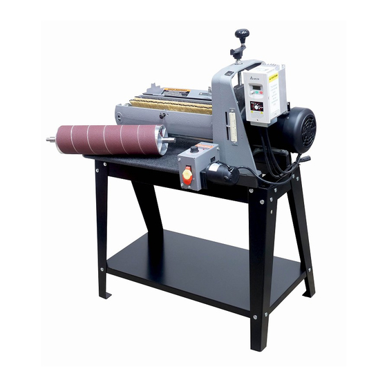
- Page 1 Owner’s Manual 19-38 Drum Sander...
- Page 2 If you have any ques- tions this manual will provide answers and you can The SuperMax 19-38 Sander comes with a two- also refer to our website or customer service for year limited warranty. We will provide replace- any updates or further details.
-
Page 3: Table Of Contents
Head Assembly ....24 19-38 DRUM SANDER . . . . . . . . . . . . . . . . 5 Parts List—Head Assembly . -
Page 4: Safety Warnings
SAFETY WARNINGS Caution, Safety First . When maintaining and operating this machine al- ways put safety first. For your own protection read and study this manual and safety precautions be- fore operating the machine. Always heed standard safety precautions including the following: •... -
Page 5: About The Supermax
Maximum Width: 38” (two passes) Minimum Length: 2 -1/4” This manual was designed to help familiarize you with your SuperMax 19-38 Drum Sander and to Maximum Thickness: 4” typical help you take advantage of its exclusive features. Minimum Thickness: 1/32” typical By understanding the major components and how ❖... -
Page 6: Quick Set Up Guide To Unpacking
QUICK SET UP GUIDE TO UNPACKING Your SuperMax 19-38 Drum Sander has been shipped mostly assembled from the factory. If any damage has occurred during shipping, notify the transportation company as soon as possible and ask for a damage and loss report. - Page 7 Install knob to height adjustment handle. First, finger tighten nut to knob. Thread stud from knob into hand wheel and tight- en nut against hand wheel. Lift points marked. 19-38 DRUM SANDER OWNER’S MANUAL Quick Set Up Guide to Unpacking...
- Page 8 A. First remove the 2 bolts on the outboard side of the conveyor belt. NOTE: SILVER PLATE Leave the silver plate, which is near the fast lever and under the motor, in place when re- moving bolts. 19-38 DRUM SANDER OWNER’S MANUAL Quick Set Up Guide to Unpacking...
- Page 9 The bolts Install two lock washers and two flat washers on the studs on outboard side of the conveyor belt. 19-38 DRUM SANDER OWNER’S MANUAL Quick Set Up Guide to Unpacking...
- Page 10 The power cord that is wrapped around the gear motor is the power cord that must be plugged into a 110 Volt, 20 Amp outlet. 19-38 DRUM SANDER OWNER’S MANUAL Quick Set Up Guide to Unpacking...
-
Page 11: Setting Up The 19-38 Drum Sander
Checking the alignment before using the sanding drum is necessary to make sure that the drum is parallel. Your SuperMax 19-38 Sander should now be in 1. Remove the abrasive on the drum. Removing place and ready for the final set-up. The sander the abrasive is necessary to make sure that the was adjusted and aligned at the factory. -
Page 12: Dust Collection
POWER AND ELECTRICAL SAFETY lel. A simple visual check that the drum is paral- The SuperMax 19-38 Drum Sander requires 110 Volt, lel is sufficient. single-phase 20-Amp service. After the dust collec- 6. -
Page 13: Abrasives
Installing and Wrapping Abrasives Accurate attachment of the abrasive strip to the drum is critical to achieving the top performance from your SuperMax 19-38 Drum Sander. Wrapping Abrasives Pre-cut wraps have been factory tapered to the specific width of your drum. If you are cutting your own abrasive, use the wrap that came on the drum as a template. -
Page 14: Abrasive Wrap Tension Adjustment
19-38 DRUM SANDER OWNER’S MANUAL Abrasives... -
Page 15: Operating The 19-38 Drum Sander
OPERATING THE 19-38 DRUM SANDER height as the abrasive in use. Place a flat piece of scrap stock under the drum with the abrasive in place. Lower the durm until the abrasive lightly touches the scrap piece of stock. Without chang-... - Page 16 .003. Never tighten the bolts all the way down. The fast The built-in versatility of the SuperMax 19-38 lever should always be able to be Drum Sander allows it to be used for a wide range moved back and forth between and of tasks.
-
Page 17: Conveyor Belt Tension
To adjust the tension of the conveyor belt, first adjust the take-up screw nut on both sides of the conveyor to obtain approximately equal tension on both sides of the belt when taut. 19-38 DRUM SANDER OWNER’S MANUAL Operating The 19-38 Drum Sander... - Page 18 It is important to pay attention to the tension roller pressure because too little pressure can result in slippage of stock on conveyor belt and kick back. Too much tension can cause snipe when sanding. 19-38 DRUM SANDER OWNER’S MANUAL Operating The 19-38 Drum Sander...
-
Page 19: Troubleshooting
TROUBLESHOOTING If you are experiencing a problem affecting the PROBLEM machine’s performance, check the following for Conveyor motor oscillates. potential causes and solutions; it may also pay to POSSIBLE CAUSE review the previous sections in this manual on set- 1. Motor not properly aligned. ting up and operating your machine. - Page 20 Clean or replace conveyor belt. SOLUTION Readjust height control Replace bearing Clean and oil threads PROBLEM Knocking sound while running. POSSIBLE CAUSE 1. Wear on the drum bearings. SOLUTION Replace bearings. Contact dealer. 19-38 DRUM SANDER OWNER’S MANUAL Troubleshooting...
- Page 21 1. Overlapped paper. 2. Improper gap in abrasive paper. The gap should SOLUTION be approximately 1/16. Increase feed rate. SOLUTION Reduce depth of cut. Adjust the abrasive so that there are proper gaps and room. 19-38 DRUM SANDER OWNER’S MANUAL Troubleshooting...
-
Page 22: Maintenance
MAINTENANCE Monthly Maintenance Checklist 6. Remove the two nuts and washers (outboard side). For best results perform the following procedures 7. Lift the conveyor and remove it from the sander. on a monthly basis: 8. Stand conveyor on motor side. •... -
Page 23: Technical Specifications
TECHNICAL SPECIFICATIONS Wiring Diagram TO GEAR MOTOR CONVEYOR... -
Page 24: Head Assembly
Head Assembly 19-38 DRUM SANDER OWNER’S MANUAL Technical Specifications... -
Page 25: Parts List-Head Assembly
27 ..480BS-127 ....Stud ......................4 28 ..480BS-128 ....Hex Cap Screw ..........3/8”-16x1-1/4” ....4 29 ..480BS-129 ....Flat Washer .............3/8” ....... 8 30 ..480BS-130 ....Hinge ......................2 19-38 DRUM SANDER OWNER’S MANUAL Technical Specifications... - Page 26 58 ..480BS-158 ....Tension Roller Bracket, Inner Right ............. 1 59 ..480BS-159 ....Pad, Bracket-Tension Roller ..............2 60 ..480BS-160 ....Bracket ...................... 2 61 ..480BS-161 ....Plate ......................1 19-38 DRUM SANDER OWNER’S MANUAL Technical Specifications...
- Page 27 87 ..480BS-187 ....Warning Label ..................1 88 ..480DS-188 ....Battery ...................... 1 89 ..480DS-189 ....Digital Readout Assembly (optional) ..........1 90 ..635DS-280 ....Fastener Tool (optional) ................ 1 19-38 DRUM SANDER OWNER’S MANUAL Technical Specifications...
-
Page 28: Conveyor And Motor Diagram
Conveyor and Motor Diagram 19-38 DRUM SANDER OWNER’S MANUAL Technical Specifications... -
Page 29: Parts List-Conveyor And Motor
27 ..480BS-227 ....Bracket, Take Up-Slide ................2 28 ..480BS-154 ....Bushing, Oilite..................4 29 ..480BS-229 ....Roller, Driven ................... 1 30 ..480BS-230 ....Wrench ...................... 2 31 ..480BS-231 ....Hex Nut ............1/4”-20 ......2 19-38 DRUM SANDER OWNER’S MANUAL Technical Specifications... - Page 30 42 ..480BS-242 ....Hex Nut ............5/16“-24 ......1 43 ..480BS-243 ....Slotted Set Screw ...........#8-36x5/16” ....1 44 ..480BS-244 ....Strain Relief, Gear Motor ......6N-4 ......1 45 ..480BS-245 ....Hex Nut ............5/16”-18 ......2 19-38 DRUM SANDER OWNER’S MANUAL Technical Specifications...
-
Page 31: Supply Checklist And Order Information
1-1/2” 619-036-1 36 Grit: Individual Wrap Closed Stand, Part # 71938-CL Optional upgrade 619-060-1 60 Grit: Individual Wrap for 19-38 Drum Sander. Built in storage and lock- 619-080-1 80 Grit: Individual Wrap able wheels. 619-100-1 100 Grit: Individual Wrap... -
Page 32: Notes
NOTES...
Need help?
Do you have a question about the 19-38 and is the answer not in the manual?
Questions and answers
how do i remove the drum from my jet sander locking pin on right hand side jumped out of place