
Related Manuals for SuperMax 19-38 DRUM SANDER


Summary of Contents for SuperMax 19-38 DRUM SANDER
- Page 1 OWNER’S MANUAL ® 269049 19-38 DRUM SANDER P. 888.454.3401 SuperMaxTools.com F. 651.454.3465 sales@SuperMaxTools.com © 03/2017 SuperMax Tools...
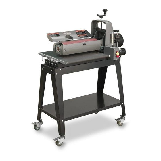
- Page 2 MODEL IDENTIFICATION Your 19-38 drum sander is one of a family of machines from SuperMax Tools designed to help you achieve re- sults comparable to industrial-size sanders at a fraction of the cost. For future reference, find the model, stock and serial numbers on the back of machine base and write them in below.
-
Page 3: Table Of Contents
.....................6 warranty ......................6 about the superMax tools druM sander ............7 unpacking your druM sander ................7 setting up your superMax tools druM sander ..........11 Checking drum alignment ..............................11 Connecting Dust Collectors .............................12 Power and Electrical Safety .............................12 abrasive selection guide .................12 Wrapping Abrasives ................................13... -
Page 4: Safety Rules
SAFETY RULES KEEP GUARDS IN PLACE and in working order. SECURE WORK. Use clamps or a vise to hold work when practical. It's safer than using your REMOVE ADJUSTING KEYS AND WRENCHES. hand and it frees both hands to operate tool. Form habit of checking to see that keys and ad- justing wrenches are removed from tool before DON'T OVERREACH. -
Page 5: Grounding Instructions
TABLE A - MINIMUM GAUGE FOR CORD AMPERAGE RATING VOLTS TOTAL LENGTH OF CORD (IN FEET) MORE MORE MINIMUM GAUGE FOR CORD THAN THAN Not recommended GROUNDING INSTRUCTIONS 1. All grounded, cord-connected tools: In the event of a malfunction or breakdown, grounding provides a path of least resistance for electric current to reduce the risk of electric shock. -
Page 6: Specifications
be used with this tool. If the tool must be reconnected for use on a different type of electric circuit, the reconnection should be made by qualified service personnel; and after reconnection, the tool should comply with all local codes and ordinances. Fig. -
Page 7: About The Supermax Tools Drum Sander
UNPACKING YOUR SUPERMAX TOOLS DRUM SANDER Your 19-38 drum sander has been shipped mostly assembled from the factory. If any damage has occurred as a result of shipment, notify the transportation company as soon as possible and ask them to make an immediate inspection. - Page 8 Assemble the SuperMax Tools 19-38 drum sander Open box 1 that contains the main sanding unit. Re- Open Stand #71938-OP or alternatively, if you have move the cardboard liner. Open the plastic bag enclo- chosen to use your own bench prepare the existing sing the sanding unit.
- Page 9 Install knob to height adjustment handle. First, finger Turn the handle and raise sanding head to higher posi- tighten nut to knob. Thread stud from knob into hand tion to remove packing block from under carriage arm. wheel and tighten nut against hand wheel. To prepare the unit for the installation of the conveyor Next remove the 2 bolts on the inboard (right) side of belt, first remove the 2 bolts on the outboard (left) side...
- Page 10 NOTE: The fast lever should be in the upright position for installation of the sanding unit. The fast lever raises the inboard (right) side of conveyor up. Do not ever tighten the bolts all the way down. The fast lever should always be able to be moved back and forth between and up/down position.
-
Page 11: Setting Up Your Supermax Tools Drum Sander
SETTING UP YOUR DRUM SANDER Your SuperMax Tools 19-38 sander should now be in place and ready for the final set-up. The sander was ad- justed and aligned at the factory. However simple alignment checks will ensure that everything is in perfect order. -
Page 12: Connecting Dust Collectors
CONNECTING DUST COLLECTORS Dust collection is necessary for the SuperMax Tools 19-38 drum sander. The sander comes equipped with a 4” diameter dust exhaust port at the top of the cover. Check to make sure that the minimum dust requirements are sufficient. -
Page 13: Wrapping Abrasives
INSTALLING AND WRAPPING ABRASIVES Accurate attachment of the abrasive strip to the drum is critical to achieving the top performance from your Su- perMax Tools 19-38 drum sander. WRAPPING ABRASIVES Abrasive strips do not have to be pre-measured. The end of the roll is first tapered and attached to the outboard (left) side of the drum. -
Page 14: Proper Abrasive Wrap Position
Pinch or squeeze the clip lever to open the clip, and The take-up fastener is designed to automatically take pull the take-up lever to the top. Insert the tapered end up any slack caused by stretching of the abrasive through the slot in the inboard (right) end of the drum. wrap. -
Page 15: Operating Your Drum Sander
OPERATING THE 19-38 DRUM SANDER Your sander will be able to perform an infinite variety of sanding projects all designed to your specifications. With some time and experimentation the proper setting and technique for each job will become apparent. DRUM DEPTH OF CUT Determining the depth of cut is the most important operating procedure decision. -
Page 16: Conveyor And Speed Rate
STOCK FEEDING MAXIMUM PERFORMANCE The built-in versatility of the SuperMax Tools 19-38 drum sander allows it to be used for a wide range of tasks. Learning to use the multiple controls to make adjustments will allow you to fine tune the machine for maximum results no matter what the job. -
Page 17: Tension Roller Pressure
• Sanding Imperfect or Tall Stock To avoid bodily injury take special care when sanding stock that is twisted, bowed or otherwise varied in thickness from end to end. If possible support such stock as it is being sanded to keep it from slipping or tipping. Use extra roller stand, assistance from another person, or hand pressure on the stock to minimize potentially hazardous situations. -
Page 18: Conveyor Belt Tension
CONVEYOR BELT TENSION Insufficient belt tension will cause slippage of conveyor belt on the drive roller during sanding ope- ration. The conveyor belt is too loose if it can be stop- ped by hand pressure applied directly to the top of the conveyor belt. -
Page 19: Cleaning The Machine
SuperMax Tools 19-38 - 3-Wraps in Box 60-19-220 220 Grit SuperMax Tools 19-38 - 3-Wraps in Box 60-19-000 Assorted box (36/80/120 grit) SuperMax Tools 19-38 - 1 each in Box NOTES For information call SuperMax Tools 1-(888)-454-3401 or visit www.SuperMaxTools.com... -
Page 20: Troubleshooting Your Supermax Tools Drum Sander
TROUBLESHOOTING YOUR SUPERMAX TOOLS DRUM SANDER Any operating problems with the drum sander will likely occur most often during the period that you are beco- ming familiar with its components and their adjustments. If you are experiencing a problem affecting the ma- chine’s performance, check the following listings for potential causes and solutions;... - Page 21 PROBLEM POSSIBLE CAUSE SOLUTION Excessive depth of cut Reduce depth of cut Tension rollers too high Lower tension rollers STOCK SLIPS ON Excessive feed rate Reduce feed rate CONVEYOR BELT CAUSING GOUGING Clean or replace conveyor Dirty or worn conveyor belt belt Belt out of adjustment Readjust belt...
-
Page 22: 19-38 - Wiring Diagram
19-38 - WIRING DIAGRAM... -
Page 23: Parts List And Diagrams
19-38 - PARTS LIST - HEAD ASSEMBLY # ..PART NO....DESCRIPTION............. SIZE ..........QTY 1 ..480DS-101 ... MOTOR .............................. 1 ..480DS-101 ..MOTOR FAN COVER ........................1 2 ..480BS-134 ... STRAIN RELIEF, MOTOR .......... 7N-2 ............. 1 3 ..480DS-103 ... MAIN CORD, MOTOR TO CONTROL BOX ................... 1 4 .. - Page 24 19-38 - PARTS LIST - HEAD ASSEMBLY # ..PART NO....DESCRIPTION............. SIZE ..........QTY 46..480BS-146 ... ROUND SOCKET HEAD CAP SCREW ....1/4”-20X1” ..........4 47..480BS-147 ... FLAT WASHER ............5/16” ............4 48..480DS-148 ... BEARING SEAT ..........................2 49..
- Page 25 19-38 - HEAD ASSEMBLY...
- Page 26 19-38 - PARTS LIST - CONVEYOR AND MOTOR # ..PART NO....DESCRIPTION............. SIZE ..........QTY 1 ..480BS-201 ... GEAR MOTOR ............90 VDC ............1 2 ..480DS-202 ... STRAIN RELIEF, POWER CORD ......6P3-4 ............1 3 ..480DS-203 ... POWER CORD ..........................1 4 ..
- Page 27 19-38 - CONVEYOR AND MOTOR...
- Page 28 SuperMaxTools.com - sales@SuperMaxTools.com P. 1-888.454.3401 - F. 1-651.454.3465...
Need help?
Do you have a question about the 19-38 DRUM SANDER and is the answer not in the manual?
Questions and answers