
Subscribe to Our Youtube Channel
Related Manuals for CH GWHD(30)ND3EO


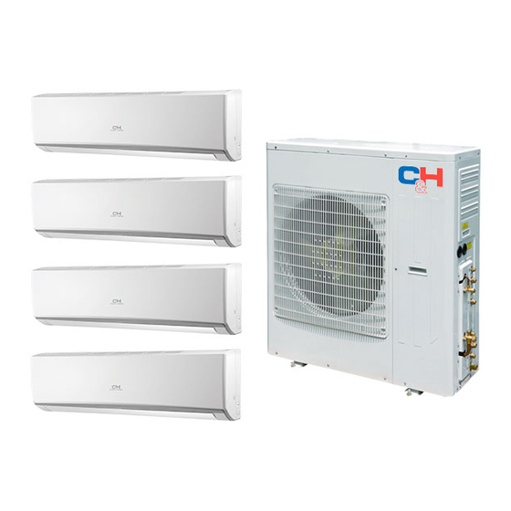
Summary of Contents for CH GWHD(30)ND3EO
-
Page 1: Heat Pump
MULTI DUCTLESS INVERTER HEAT PUMP OUTDOOR UNIT Installation manual Models: GWHD(30)ND3EO GWHD(36)ND3EO GWHD(42)ND3EO... -
Page 2: Table Of Contents
TABLE OF CONTENTS PAGE SAFETY CONSIDERATIONS......2 INDOOR UNITS COMBINATIONS ..... 3 PREFACE . -
Page 3: Safety Considerations
SAFETY CONSIDERATIONS CAUTION Installing, starting up, and servicing air- -conditioning equipment can be hazardous due to system pressures, electrical components, EQUIPMENT DAMAGE HAZARD and equipment location (roofs, elevated structures, etc.). Failure to follow this caution may result in equipment Only trained, qualified installers and service mechanics should damage or improper operation. -
Page 4: Indoor Units Combinations
INDOOR UNITS COMBINATIONS Specifications are subject to change without notice. -
Page 5: Preface
Preface Please carefully read the instructions in this manual before installation and operation. (1) For personal safety, please follow the instructions provided in this manual. (2) The total capacity of the indoor units , which run at the same time, can not exceed that of the outdoor units;... -
Page 6: Product Introduction
2 Product Introduction The Multizone system adopts inverter compressor technology. According to change displacement of compressor, stepless capacity regulation within range of 15%~120% can be realized. V arious product lineup is provided with capacity range from 30KBtu to 42KBtu, which can be widely used in a boarding house , a working area and especially applicable in a location with a variable load change. - Page 7 9,000 GWH09QC-D3DNA1D/I High Wall 12,000 GWH12QC-D3DNA1D/I 18,000 GWH18QD-D3DNA1G/I 09,000 GTH(09)BA-D3DNA1A/I 12,000 GTH(12)BA-D3DNA1A/I Flooring ceiling 18,000 GTH(18)BA-D3DNA1A/I 24,000 GTH(24)BA-D3DNA1A/I 09,000 GFH(09)EA-D3DNA1A/I GWHD(30)ND3EO GWHD(36)ND3EO 12,000 GFH(12)EA-D3DNA1A/I 18,000 Duct type GFH(18)EA-D3DNA1A/I GWHD(42)ND3EO 21,000 GFH(21)EA-D3DNA1A/I 24,000 GFH(24)EA-D3DNA1A/I 12,000 GKH(12)BA-D3DNA2A/I 18,000 Cassettle type GKH(18)BA-D3DNA2A/I 24,000...
- Page 8 2.3 Rated working condition Table 2 Indoor side state Outdoor side state Dry buib temp. Wet buib temp. Dry buib temp. Wet buib temp. Rating cooling 80.06 66.92 75.02 Rating Heating 69.98 60.08 43.00 NOTICE 1) The following listed cooling /heating capacity and noise is tested before shipping. 2) The parameters below are tested under a rated working condition.
-
Page 9: Preparation Before Installation
3 Preparation before Installation 3.1 Standard parts Please use the following standard parts included with the air conditioning units. Table 4 Outdoor Unit Parts Name Picture Number Quantity Remark Owner's manual Tube connector subassy 3.2Selecting the installation site 1) Install the unit in a location that can withstand the weight of the unit and make sure the unit does not shake or fall off. -
Page 10: Piping Connection
3.3 Piping Connection The maximum pipe length is shown in the following table. When the distance between units (piping length) is out of the range listed below, normal operation of the unit can not be guaranteed. Table 5 Connecting Pipe (inch) Max. -
Page 11: Installation
4 Installation 4.1 Outline and dimension of the outdoor unit 3 0 K Outline dimension and mounting holes 14 4/7 36 2/9 38 3/7 17 1/3 Unit:inch Fig 4 3 3 3 8GJQG36---3 36K, Outline dimension and mounting holes 14 1/4 42 1/2 17 1/3 24 5/6... -
Page 12: Installation Of The Connection Pipe
4.2 Installation of the Connection Pipe Connecting piping for the indoor unit and outdoor unit are in the manifold mode (see the figure below). Fig 6 4.2.1 Piping between the Indoor and Outdoor Units (1) If the liquid and gas stop valves, which have the sign A , B, C, D or E , have not been connected to the indoor units, turn off the screw cap with the spanner airproof. - Page 13 Allowable Length and Height for the Refrigerant Pipe Table 7 Allowable V alue Fitting Pipe Total length (actual length) of fitting +…+L 229.6ft 246.1ft pipe Length of farthest fitting pipe (ft) 82ft 82ft X=1 2 3 4,5 Outdoor unit at Height difference 49.2ft 49.2ft...
- Page 14 4.2.3 Installation of the Refrigerant Pipe Protection Layer The refrigerant refrigerant pipe should be insulated by the insulating material and plastic tape to prevent condensation and water leakage. The joints of the indoor unit should be wrapped with the insulating material.Ensure there is no gap on the joint of the indoor unit, as shown in Fig.9.
-
Page 15: Air Purging
4.3 Air Purging and Refrigerant Charge 4.3.1 Air purging (1) The refrigerant in the outdoor unit was charged before shipment. Additional refrigerant needs to be charged into the refrigerant pipe during the field installation. (2) Ensure the outdoor unit's liquid and gas valves are closed completely. (3) As shown in the following figure (Fig.10), expel the gas inside the indoor unit and the refrigerant pipe with the vacuum pump. -
Page 16: Electric Wiring
Table 8 Warning Models Power Supply Capacity of the breaker A 208/230V~60Hz 208/230V~60Hz 208/230V~60Hz GWHD(30)ND3EO OUTDOOR UNIT INDOORUNIT A INDOORUNIT B INDOORUNIT D INDOORUNIT C Fig 11 GWHD(36)ND3EO、GWHD(42)ND3EO OUTDOOR UNIT... - Page 17 4.4.2 Grounding Requirements (1) The air conditioner is classified as a Class I appliance, so its grounding must be reliable. (2) The yellow-green line of the air conditioner is the ground and can not be used for any other purpose, cut off or fixed by the tapping screw;...
-
Page 18: Troubleshooting
5 Troubleshooting 1) In the event of abnormal conditions (for example, a foul smell), shut off the main power supply immediately and contact your Service Center.Operating under abnormal conditions would damage the air conditioning unit and would cause electric shock or a fire hazard. 2) Do not attempt to repair the air conditioning.Contact a professionally skilled technician at the appointed service center. -
Page 19: Into Errors
6 The conditions listed below are not classified into errors. Table 10 Conditions Causes When restart the unit soon after it is The overload protection switch of the unit let the stopped. startup delayed for three minutes. The unit does not run The unit will stand by for approximate one As soon as power is on. - Page 20 running next operation Mode conflict COOL or HEAT mode can not When the indoor operating mode conflicts with that of be operated outdoor unit, indoor fault indicator will flash and conflict will be shown on the wired controller after 5 minutes. Indoor unit stops to run and meanwhile change outdoor operating mode as the same as that of indoor unit, then the unit will go back to normal.
- Page 21 7 Troubleshooting The error code will be displayed on the wired controller and the main board of the outdoor unit The meaning of each error, as shown in table 13. Table 12 The indicator display Name of malfunction Yellow light Red light Green light Compressor runs...
-
Page 22: Maintenance
7 Maintenance A regular inspection, maintenance and care should be performed by professional personnel, which will prolong the unit's life span. 7.1 Outdoor heat exchanger The outdoor heat exchanger should be cleaned once every two months. Use a vacuum cleaner with a nylon brush to clean up dust and small particles on the surface of the heat exchanger. - Page 23 www.cooperandhunter.us MANUFACTURER: GREE ELECTRIC APPLIANCES, INC. OF ZHUHAI Add: West Jinji Rd, Qianshan, Zhuhai, Guangdong, China, 519070...
Need help?
Do you have a question about the GWHD(30)ND3EO and is the answer not in the manual?
Questions and answers