Advertisement
Quick Links
Download this manual
See also:
Manual
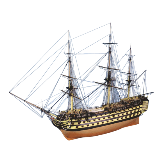
H.M.S V
1805
ICTORY
Exact scale model of the 100-Gun British Ship of the Line.
This, the fifth ship of the Royal Navy to bear the name Victory, had three major battle honours. The
first being the Battle of Ushant 1781, the second, the Battle of St. Vincent 1797 and the third, for
which she is most famed, the Battle of Trafalgar 1805. By the end of the Battle of Trafalgar, there was
not a mast, spar, shroud or sail on board Victory that had not been severely damaged, lost or destroyed
in the conflict.
Manual 2 of 3
Masting & Rigging
Additional photos of every stage of construction can be found on our website at:
http://www.jotika-ltd.com
Nelsons Navy Kits manufactured and distributed by JoTiKa Ltd.
Model Marine Warehouse, Hadzor, Droitwich, WR9 7DS.
Tel ~ +44 (0) 1905 776 073
Fax ~ +44 (0) 1905 776 712
Email ~ nelsonsnavy@jotika-ltd.com
Advertisement

Related Manuals for Jotika H.M.S. Victory 1805


Summary of Contents for Jotika H.M.S. Victory 1805
- Page 1 Masting & Rigging Additional photos of every stage of construction can be found on our website at: http://www.jotika-ltd.com Nelsons Navy Kits manufactured and distributed by JoTiKa Ltd. Model Marine Warehouse, Hadzor, Droitwich, WR9 7DS. Tel ~ +44 (0) 1905 776 073 Fax ~ +44 (0) 1905 776 712 Email ~ nelsonsnavy@jotika-ltd.com...
- Page 2 When complete, glue the crosstree and trestletree assembly to the underside of the top platform. At this stage, put the lower mast and top assembly to one side, do not glue them to one another. © 2003 JoTiKa Ltd.
- Page 3 The topmast sheaves, constructed earlier can now be fitted. Identify the foremast cap saddles (348 & 349) and secure to the cap as shown on Plan Sheet 10 & (Fig 036). Finally locate and fit the mast finishing cap (347). © 2003 JoTiKa Ltd.
- Page 4 Both the lower mast caps and topmast caps are at 90 degrees to the mast, i.e. they are not parallel to the keel. Remember to fit the boarding pike rack into position as described for the fore mast. © 2003 JoTiKa Ltd.
- Page 5 Note: when instructed to use the pre-cut blocks (10mm & 7mm open heart blocks, 10mm triple & double jeer blocks and the 8.5mm triple cat blocks), you will need to file a slight groove around the outer edge to take the strop as shown (Photo 041). © 2003 JoTiKa Ltd.
- Page 6 Identify, paint and assemble the small Admiral’s lantern components (540, 658 & 659). The lantern can be assembled in the same manner as the transom lanterns. The lantern is fitted, on brass wire, into the centre of the aft face of the main top. Fig 032 © 2003 JoTiKa Ltd.
- Page 7 Fore Lower Top Blocks Fig 033 Fore Lower Top (‘Top’) Fig 034 Fore Lower Top (Underside) © 2003 JoTiKa Ltd.
- Page 8 Fore Topmast Top Blocks Fig 035 Fore Topmast Top Fore Lower Mast Cap Blocks Fig 036 Fore Lower Mast Cap © 2003 JoTiKa Ltd.
- Page 9 Main Lower Top Blocks Fig 037 Main Lower Top (‘Top’) Fig 038 Main Lower Top (Underside) © 2003 JoTiKa Ltd.
- Page 10 Main Topmast Top Blocks Fig 039 Main Topmast Top Main Lower Mast Cap Blocks Fig 040 Main Lower Mast Cap © 2003 JoTiKa Ltd.
- Page 11 Mizzen Lower Top Blocks Fig 041 Mizzen Lower Top (‘Top’) Fig 042 Mizzen Lower Top (Underside) © 2003 JoTiKa Ltd.
- Page 12 Mizzen Topmast Top Blocks Fig 043 Mizzen Topmast Top Mizzen Lower Mast Cap Blocks Fig 044 Mizzen Lower Mast Cap © 2003 JoTiKa Ltd.
-
Page 13: Standing Rigging
0.5mm black thread. For the topmasts, there is one pair on each side of the fore and main and none on the mizzen. These are again constructed in the same manner as the lower mast pendants from 0.75mm black thread. © 2003 JoTiKa Ltd. - Page 14 Plan Sheet 18 and secure them into position (inboard) with 0.1mm natural thread . The cleats and 0.1mm thread should be painted black when in position. Finish the ratlines, brush on watered down PVA and finally trim the ratlines only when dry. Note: the ratlines on Victory are not black. © 2003 JoTiKa Ltd.
- Page 15 The preventer stay collar passes through the foremost hole in the marines’ walk and around the bowsprit. The main preventer stay closed heart block is lashed to the main preventer stay collar open heart block with 0.5mm natural thread. © 2003 JoTiKa Ltd.
- Page 16 The snaking is 0.1mm natural thread and alternates from the fore mast stay to the fore mast preventer stay and back for the full length between the eye and mouse and closed heart blocks, forming a zigzag pattern. It is advisable to use either an over hand or marling hitch knot at each point. © 2003 JoTiKa Ltd.
- Page 17 5mm double block seized around the first deadeye strop (from the front) on the channel. The falls are made of 0.25mm natural and are belayed to the breast backstay above the 5mm single block. © 2003 JoTiKa Ltd.
- Page 18 (Fig 033). The block and tackle are made up of a 3mm single and 3mm double block into an eyelet with 0.25mm natural falls. The running end of the tackle then runs through the ‘top’ and belays to the main top bowline bitts, pin 4, (b12). © 2003 JoTiKa Ltd.
- Page 19 1mm black thread either end of which is hooked to copper eyelets in the hull as shown on Plan Sheet 11. © 2003 JoTiKa Ltd.
-
Page 20: Running Rigging
(approximately 50mm long) seized to a copper eyelet at the rear of the fore channel. The falls are of 0.25mm natural and belay to the aftermost kevel on the forecastle (adjacent to the belfry) (b18). © 2003 JoTiKa Ltd. - Page 21 Plan Sheet 15. A tackle is formed between the two blocks and the falls are belayed to the medium cleat (b25) on the poop deck directly in front of the large main brace cleat. © 2003 JoTiKa Ltd.
- Page 22 The leechlines are of 0.25mm natural and are set up in the same manner as the buntlines but pass through the outermost sheave in the outer 3mm double blocks under the top. They then pass down and belay to the 1st and 8th forecastle breast beam supports (b30). © 2003 JoTiKa Ltd.
- Page 23 The buntlines are of 0.25mm natural thread and are rigged as per the fore topmast yard. They come down outside the tops and belay to the third pin of the fife rail abreast the main mast (b38). © 2003 JoTiKa Ltd.
- Page 24 The clueline is of 0.25mm natural thread and the standing end is made fast to the spritsail topsail yard as shown on Plan Sheet 16. It reeves through the 3mm sheet block, back up through the 3mm clueline block and belays to the beakhead fife rail (b48). © 2003 JoTiKa Ltd.
- Page 25 The spritsail topsail brace is of 0.25mm natural thread. The brace is made fast to the end of the spritsail topsail yard and reeves under the fore top, through the 3mm single blocks (fore and aft). They then pass down and belay to the 4th and 5th timberheads abreast the belfry (b62). © 2003 JoTiKa Ltd.
- Page 26 (from the front) on the large fife rail on the quarterdeck (b69). The port brace is rigged in the same manner. The Mizzen Topmast and Topgallant Yards: The mizzen topmast and topgallant yard braces will be rigged with the driver gaff. © 2003 JoTiKa Ltd.
- Page 27 A tackle is set up between these two blocks and the running end belays to the small cleat on the starboard inner transom knee (b78) The ensign staff should now be shipped. © 2003 JoTiKa Ltd.
- Page 28 Fig 048 Rigging sequences for the end of the driver boom & gaff © 2003 JoTiKa Ltd.
- Page 29 7mm single block seized to the boomkin outside the standing end, and belays to the top of the headrail (b81). For the benefit of the model, when the clueline, sheet and tack are finally rigged there should be no slack. © 2003 JoTiKa Ltd.
- Page 30 A thimble is formed in the end of the lift around the centre of the span. The running end travels up and through the 7mm single blocks (one per side) seized in a span under the bibbs of the mizzen mast and belay to the mizzen circular fife rail (b86). Fig 050 © 2003 JoTiKa Ltd.
- Page 31 The sheet anchors are secured in a similar manner as shown, but without a cable. Again ensure the anchor palm rests in the anchor palm block. The kedge anchor is secured to the aft end of the starboard mizzen channel by a strop. Photo 042 Photo 043 Bower Anchor Sheet Anchor © 2003 JoTiKa Ltd.
- Page 32 5mm down from the top of the hull for the launch and barge and 4mm down from the top of the hull for the pinnace and cutter. With the line marked, fit the ‘rising plank’. The ‘rising plank is 1.5x1.5mm walnut (sanded to 1.5x1mm) for the barge, pinnace and cutter and 1x3mm walnut for the launch. © 2003 JoTiKa Ltd.
- Page 33 The boats can now be glued in position and lashed to the skid beams. Fig 051 File a small notch in the after end to accept a rope. Glue the two halves together, profiled surface to profiled surface. © 2003 JoTiKa Ltd.
- Page 34 Launch (Actual Size) Fig 052 © 2003 JoTiKa Ltd.
- Page 35 Note: there were no hard and fast rules for ships boat paint schemes and the gunwale and washstrake colours were often switched (black gunwale, yellow Internal hull detail washstrake) © 2003 JoTiKa Ltd.
- Page 36 Barge (Actual Size) Fig 053 © 2003 JoTiKa Ltd.
- Page 37 The gunwale is olive green with gold banding. The washstrake above the gunwale is dull white. The transom is painted olive green with continuations of the gold bands. Internal hull detail, note blue and gold bands around the inner transom © 2003 JoTiKa Ltd.
- Page 38 Pinnace (Actual Size) Fig 054 © 2003 JoTiKa Ltd.
- Page 39 Note: there were no hard and fast rules for ships boat paint schemes and the gunwale and washstrake colours were often switched (black gunwale, yellow washstrake) Internal hull detail, note fore raised deck © 2003 JoTiKa Ltd.
- Page 40 Cutter (Actual Size) Fig 055 Photo 059 Photo 060 If desired, a grating (deck) can be constructed for the cutter Deck fitted from 0.5x3mm walnut (cut to 0.5x1.5mm) © 2003 JoTiKa Ltd.
- Page 41 (black gunwale, yellow washstrake) Internal hull detail JoTiKa Ltd., Model Marine Warehouse, Hadzor, Droitwich, WR9 7DS, UK. Tel: +44 (0) 1905 776 073 Fax: +44 (0) 1905 776 712 Email: Nelsonsnavy@jotika-ltd.com Web Address: http://www.jotika-ltd.com...
Need help?
Do you have a question about the H.M.S. Victory 1805 and is the answer not in the manual?
Questions and answers