Table of Contents
Advertisement
Advertisement
Table of Contents
Troubleshooting

Subscribe to Our Youtube Channel
Related Manuals for Atlas Copco QAS 250-330 JD T4i


Summary of Contents for Atlas Copco QAS 250-330 JD T4i
- Page 1 Instruction Manual for AC Generators English QAS 250-330 JD T4i...
- Page 3 QAS 250-330 JD T4i Instruction Manual for AC Generators Instruction manual ................5 Circuit diagrams ................65 Original instructions Printed matter Nr 1310 3012 57 ATLAS COPCO - PORTABLE ENERGY DIVISION 03/2012 www.atlascopco.com...
- Page 4 Neglecting maintenance or making changes to the setup of the machine can result in major hazards, including fire risk. While every effort has been made to ensure that the information in this manual is correct, Atlas Copco does not assume responsibility for possible errors.
-
Page 5: Table Of Contents
Please read the following instructions carefully before starting to use your machine. While every effort has been made to ensure that the information in this manual is correct, Atlas Copco does not assume responsibility for possible errors. Atlas Copco reserves the right to make changes without prior notice. -
Page 6: Safety Precautions For Portable Generators
Skill level 3: Electrical technician The policy of Atlas Copco is to provide the users of their manufacturer’s approval in writing. An electrical technician is trained and has the same equipment with safe, reliable and efficient products. - Page 7 Safety during transport and installation 8 All regulating and safety devices shall be maintained 6 To lift heavy parts, a hoist of ample capacity, tested with due care to ensure that they function properly. and approved according to local safety regulations, To lift a unit, all loose or pivoting parts, e.g.
- Page 8 20 Do not open electrical cabinets, cubicles or other otherwise stated in the Atlas Copco Instruction Book special warning to that effect shall be placed at each equipment while voltage is supplied. If such cannot be (AIB).
- Page 9 25 If the generator is used as stand-by for the mains 2 Parts shall only be replaced by genuine Atlas Copco prevent the sound pressure level from increasing. supply, it must not be operated without control system replacement parts.
- Page 10 Battery safety precautions 21 Make sure that oil, solvents and other substances likely to pollute the environment are properly Batteries disposed of. When servicing batteries, always wear protecting 22 Before clearing generator after clothing and glasses. maintenance or overhaul, submit it to a testrun, check 1 The electrolyte in batteries is a sulphuric acid solution that the AC power performance is correct and that the which is fatal if it hits your eyes, and which can cause...
-
Page 11: Leading Particulars
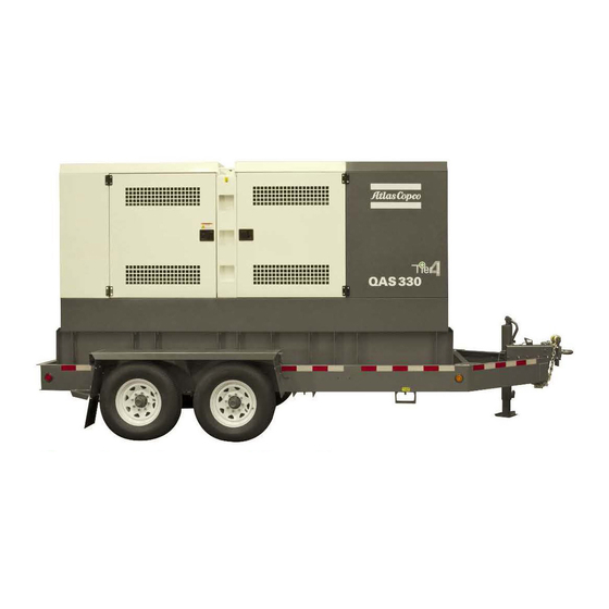
Leading particulars General description The QAS 250-330 is an AC generator, built for continuous running at sites where no electricity is available or as stand-by in cases of interruption of the mains. The generator operates at 60 Hz, 480 V - 3 phase, 240 V - 3 phase and 240 V 1 phase. The QAS 250-330 generator is driven by a water-cooled diesel engine, manufactured by John Deere. An overview of the main parts is given in the diagram below. - Page 12 Alternator Air filter Coupling Drain flexible engine oil Engine Fuel Cooler Filler cap engine oil FCW Filler cap cooling water Fuel filter Battery Intercooler Oil filter Engine oil level dipstick Pre-Filter Battery switch - 12 -...
-
Page 13: Bodywork
Bodywork Markings Use PAROIL E only. The alternator, the engine, the cooling system, etc. are A brief description of all markings provided on the enclosed in a sound-insulated bodywork that can be generator is given hereafter. Indicates the external fueltank. opened by means of side doors (and service plates). -
Page 14: Drain Plugs And Filler Caps
Drain plugs and filler caps External fuel tank connection Control and indicator panel Qc1002™ The drain holes for the engine oil, the coolant and the plug The external fuel tank connection allows to bypass the General description Qc1002™ control panel for the fuel, are located and labelled on the frame, the fuel internal fuel tank and to connect an external fuel tank to drain plug at the front, the others at the service side. - Page 15 Qc1002™ Module Pushbutton and LED functions Position I: Voltage is applied to the Qc1002™ module, it is possible to start up the generator. Following pushbuttons are used on the Qc1002™ X7 ... Flanged Inlet Used to supply power to the available coolant ENTER: Is used to select and heater or battery charger (if ordered).
- Page 16 Following LEDs are used on the Qc1002™ Qc1002™ Menu Overview This view shows a number of Parameter settings and gives access to them. At Qc1002™, the LCD will show following information: An overview is given in “Parameter list” on page 18. –...
- Page 17 Battery Voltage display Voltage - frequency - running hours display possible shutdown due to high soot level. Station Regen. Battery 25.2 V 00168.1h This view shows the Battery voltage and the running This view shows the voltage, frequency and running hours.
- Page 18 Parameter list Qc1002™ Menu Description This menu is used to select the type of engine electronics, the Qc1002™ controller should communicate with via the The Parameter Menu's are pre-programmed! Status Display (pop-up window) Canbus. A password will be asked for when an attempt to change a It's possible to scroll between configuration menu's by setting is about to be done (user password = 2003).
- Page 19 This is the described menu flow for changing the unit type: - 19 -...
- Page 20 Alarm Display (pop-up window) Following general groups of Alarms exist: GENERATOR – Warning: Alarm LED lights up + Alarm pop-up appears OVER- on the display + Alarm relay is empowered (if configured) FREQUENCY – Trip of GB: ‘Warning’ actions + Generator Contactor opens GENERATOR –...
- Page 21 LOG list Displaying the engine DM1 alarm turbo boost pressure The unit will keep an event log of the latest 30 events. Besides some engine specific alarms shown in the SPN104 "TURBO OIL PRESS" standard alarm list, also all Diagnostic messages DM1 turbo oil pressure Events are: (active alarms) can be shown on the display.
- Page 22 (RUN). Stationary Regeneration Procedure Atlas Copco recommends that the DPF configuration be left in the AUTO mode at all times, however in the event that a stationary or manual regeneration in desired the following process should be followed. – Go to the "STATION REGEN" screen. For normal operation this should be in OFF mode.
-
Page 23: Dpf Information - Indicators
DPF INFORMATION - INDICATORS Indicators Discription Operator Action Exhaust Filter Cleaning Indicator Active when: Machine can be operated as normal. If operating in an area where high 1. Exhaust gas temperature is high. exhaust temperature may be an issue, abort exhaust filter cleaning by using the 2. -
Page 24: Control And Indicator Panel Qc4002
Control and indicator panel Qc4002™ Qc4002™ module S20... ON/OFF switch Position O: No voltage is applied to the Qc4002™ General description Qc4002™ control panel module, the generator will not start. Position I: Voltage is applied to the Qc4002™ module, it is possible to start up the generator. X25... - Page 25 (GB) ON LED green light indicates that the DOWN: Decreases the value of the generator breaker is closed. STOP: Stop of the gen-set if SEMI- selected set point (in the setup menu). LED yellow light indicates that the AUTO or MANUAL is selected. In the daily use display, this button generator breaker has received a command function is used for scrolling the View...
- Page 26 Qc4002™ menu overview – The SETUP view shows the module name, the software version, the date and the time. Main View – The V3 view shows the application type and the mode, and The display has 4 different lines. The information on these some generator measurements.
- Page 27 The following menus can only be reached using the JUMP button: – 9000Software version – 9020Service port – 911XUser password Level 2 and Level 3 passwords can only be set through the Atlas Copco Utility Software PC Software. – 9120Service menu – 9130Single/Split/Three phase - 27 -...
- Page 28 This is the described menu flow: The menu flow is similar in the CONTROL SETUP, I/O SETUP and SYSTEM SETUP. For more details on the Setup menu we refer to the Qc4002™ User Manual. - 28 -...
- Page 29 In order to receive the default parameters for your unit, will be asked for a password before the change can be please contact Atlas Copco Service staff. made. It is not possible to select ‘block mode’ when running feedback is present.
- Page 30 Diagnostics menu Island operation – AMF with back synchronisation: This application is possible in combination with SEMI- This diagnostics menu can be entered via channel 6700. When the mains returns, the unit will synchronise the mains AUTO mode or AUTO mode. The internal real time clock This menu is used for engine diagnostics situations.
- Page 31 Load Take Over (LTO) operation power can be exported to the mains or imported from the – Mains breaker control lines have to be wired to X25.13/ X25.14/X25.15/X25.16. These terminals are voltage free mains, but always at a constant level. This application is normally used in combination with contacts.
- Page 32 Paralleling needs to be programmed in the application that is required • G1 & G2 are running; at 410 kW load (200 kW + 300 kW - 90 kW) => G3 will be started. (AMF, LTO, FP, MPE) and AUTO mode. Prior to starting parallel operation of two generators, –...
- Page 33 Only with Power Transducer (*) (*) A Power Transducer is a device that measures the actual power of the mains and which translates this into a 4...20 mA signal towards the Qc4002™ module. For details, please contact Atlas Copco. Installations with more generators...
- Page 34 The installation can contain up to 16 Qc4002™ modules. If the Mains is included in the installation, then an extra Qc4002™ module is required. The installation can be monitored and controlled via the PMS Software Package. For details on this application, please contact Atlas Copco.
-
Page 35: Output Terminal Board
Output terminal board Battery switch Position O on switch S13 will only be The cubicle provides a terminal board for easier The battery switch is situated inside the sound-insulated used in conjunction with an external connection of cables. It is situated below the control and bodywork. -
Page 36: Operating Instructions
The protective ventilation so that the cooling air is not recirculated. If system against excessive contact voltage necessary, consult Atlas Copco. is not effective unless a suitable earthing – Leave enough space for operation, inspection and is made. -
Page 37: Exhaust Filter System
EXHAUST FILTER EXHAUST FILTER / DIESEL PARTICULATE 3. Use Atlas copco “PAROIL E mission Green Low SAPS” engine oil. FILTER ASH HANDLING AND DISPOSAL 4. Use only ultra low sulfur fuel. Under federal, state, and/or local laws or regulations, Diesel Particulate Filter ash In addition to soot, ash deposits will also slowly build up may be classified as a hazardous waste. - Page 38 – Connect the wires to the proper terminals (L1, L2, L3, N Consult Atlas Copco for measures against the adverse and PE) of X1 and tighten the bolts securely. influence of non-linear loads. ...
-
Page 39: Before Starting
Before starting – With the generator standing level, check the engine oil level and top up if necessary. The oil level must be near to, but not exceed the high mark on the engine oil level dipstick. – Check the coolant level in the expansion tank of the engine cooling system. -
Page 40: Operating Qc1002
Operating Qc1002™ Stopping Qc1002™ – Check for leakage of oil, fuel or coolant. – Avoid long low-load periods (< 30%). In this case, an To stop the unit locally, proceed as follows: Starting Qc1002™ output drop and higher oil consumption of the engine –... -
Page 41: Operating Qc4002
Operating Qc4002™ Never turn the optional battery switch to OFF during operation. Starting Qc4002™ If circuit breaker Q1.1 trips off during operation, switch – Turn the battery switch to ON. off the load and stop the generator. Check and, if –... -
Page 42: Maintenance
1310 3129 84 For the most important subassemblies, Atlas Copco has developed service kits that combine all wear parts. These service kits offer you the benefits of genuine parts, save on administration costs and are offered at reduced price, compared to the loose components. Refer to the parts list for more information on the contents of the service kits. - Page 43 Generators in standby application have to be tested on a regular basis. At least once a month the engine should run for one hour. If possible a high load (> Inspection by Atlas Copco Service technician 30%) should be applied so that the engine reaches its operating temperature.
-
Page 44: Engine Maintenance
Engine fuel specifications procedure to synthetic oil, run the unit For fuel specifications, please contact your Atlas Copco for a few minutes to allow good and Customer Center. complete circulation of the synthetic oil. Then drain the synthetic oil again and fill again with new synthetic oil. - Page 45 Powerful oxidation resistance, high chemical PAROIL has an excellent Total Base Number (TBN) PAROIL from Atlas copco is the ONLY oil tested and stability and rust- inhibiting additives help reduce retention and more alkalinity to control acid formation.
-
Page 46: Engine Oil Level Check
Atlas Copco compressors and generators. Atlas Copco's PARCOOL EG extended life coolant is the new range of organic coolants purpose designed to meet the needs of modern engines. PARCOOL EG can help prevent leaks caused by corrosion. -
Page 47: Coolant Check
– Check the pH value of the coolant using a pH-measuring device. – Flush twice with clean water. Used coolant must be – The pH-meter can be ordered from Atlas Copco with part disposed or recycled in accordance with laws and local number 2913 0029 00. -
Page 48: Storage Of The Generator
Storage of the generator Storage – Store the generator in a dry, frost-free room which is well ventilated. – Run the engine regularly, e.g. once a week, until it is warmed up. If this is impossible, extra precautions must be taken: •... -
Page 49: Checks And Trouble Shooting
Checks and trouble shooting Never perform a test run with connected power cables. Never touch an electrical connector without a voltage check. When a failure occurs, always report what you experienced before, during and after the failure. Information with regard to the load (type, size, power factor, etc.), vibrations, exhaust gas colour, insulation check, odours, output voltage, leaks and damaged parts,... -
Page 50: Alternator Troubleshooting
Alternator troubleshooting Symptom Possible cause Corrective action Alternator gives 0 Volt Blown fuse. Replace fuse. Excite the alternator by applying a 12V battery voltage with a 30 resistor in series on the + No residual voltage. and - terminals of the electronic regulator, respecting the polarities. After being excited the alternator still gives 0 Volt. -
Page 51: Options Available For Qas 250-330 John Deere Units
Options available for QAS 250-330 John Deere units Circuit diagrams Outlet sockets (S) A brief description of all outlet sockets and circuit The engine control circuit diagrams and the power circuit breakers provided on the generator is given hereafter: diagrams for the standard QAS 250-330 John Deere units, for the units with options and for the units with combined options are: Power circuit... - Page 52 activated, Q3 interrupts the three phases towards Q1.1 . Circuit breaker for low voltage, high current X3. It can be activated again after eliminating the Circuit breaker Q1.1 and Q1.2 does not Interrupts the low voltage power supply towards problem. only interrupt the power supply towards X1 when a short-circuit occurs at the load side or socket X1 but also towards X2, X3, X4...
-
Page 53: Overview Of The Mechanical Options
Overview of the mechanical options The following mechanical options are available: – Quick couplings – Technical specifications – Technical specifications Desciption of the mechanical options Quick couplings The option Quick couplings allows to bypass the internal fueltank and to connect an external fueltank to the unit. External fuel tank connection External fuel tank return connection Make sure that:... -
Page 54: Technical Specifications
Technical specifications Technical specifications for QAS 250 JD T4i Readings on gauges Gauge Reading Unit Ammeter L1-L3 (P1-P3) Below max. rating Voltmeter (P4) Below max. rating Settings of switches Switch Function Activates at Engine oil pressure Shut down 0.5 bar Engine coolant temperature Shut down 103°C... - Page 55 Specific fuel consumption at full load (100%) 0.22 kg/kWh Fuel autonomy at full load 37 h Max. oil consumption at full load Maximum sound power level (LPA) measured according to Atlas copco spec. 74 dB(A) 9822087700 Useful capacity of fuel tank 450 gal...
- Page 56 Technical specifications for QAS 250 JD T4i 60 Hz Engine Standard ISO 3046 ISO 8528-2 Make John Deere Model 6090HFG94 Rated net output 237 kW rating type acc. ISO 3046-7 ICXN Coolant water Combustion system direct injection Aspiration turbocharged intercooled Number of cylinders Swept volume Speed governing...
- Page 57 (b) thermal release is higher at 25°C Derating table (in %, 100% is declarated power at “Performance data”) Temperature Height (°C) 1000 1500 2000 2500 3000 3500 4000 For use of generator outside these conditions, please contact Atlas Copco. - 57 -...
-
Page 58: Technical Specifications For Qas 330 Jd T4I
Technical specifications for QAS 330 JD T4i Readings on gauges Gauge Reading Unit Ammeter L1-L3 (P1-P3) Below max. rating Voltmeter (P4) Below max. rating Settings of switches Switch Function Activates at Engine oil pressure Shut down 0.5 bar Engine coolant temperature Shut down 103°C Specifications of the engine/alternator/unit... - Page 59 Specific fuel consumption at full load (100%) 0.224 kg/kWh Fuel autonomy at full load 24.4 h Max. oil consumption at full load Maximum sound power level (LPA) measured according to Atlas copco spec. 74 dB(A) 9822087700 Useful capacity of fuel tank 430 gal...
- Page 60 Technical specifications for QAS 250 JD T4i 60 Hz Make John Deere Model 6090HFG95 Rated net output 323 kW rating type acc. ISO 3046-7 ICXN Coolant water Combustion system direct injection Aspiration turbocharged intercooled Number of cylinders Swept volume Speed governing electronic HPCR Capacity of oil sump...
- Page 61 (b) thermal release is higher at 25°C Derating table (in %, 100% is declarated power at “Performance data”) Temperature Height (°C) 1000 1500 2000 2500 3000 3500 4000 For use of generator outside these conditions, please contact Atlas Copco. - 61 -...
-
Page 62: Conversion List Of Si Units Into British Units
Conversion list of SI units into British units 1 bar 14.504 psi 0.035 oz 1 kg 2.205 lbs 1 km/h 0.621 mile/h 1 kW 1.341 hp (UK and US) 0.264 US gal 0.220 lmp gal (UK) 0.035 cu.ft 3.281 ft 1 mm 0.039 in 1 m³/min... -
Page 63: Dataplate
Dataplate - 63 -... -
Page 64: Disposal
(for example sand, sawdust) and dispose recyclable materials. it according the applicable local disposal regulations. Do Your Atlas Copco generator consists for the most part of not drain into the sewage system or surface water. metallic materials, that can be remelted in steelworks and smelting works and that is therefore almost infinite recyclable. - Page 65 Circuit diagrams - 65 -...
- Page 66 1310 3200 12/00 Applicable for QAS 250-330 - Qc1002™, Engine Circuit - 66 -...
- Page 67 - 67 -...
- Page 68 Mark Name Control Module (Configure in UNIT-type Fuel Level Sensor Engine controller Fuse Fuse Battery 24V Panel Light Engine connector Starter Relay Starter Motor P1-3 A-Meters V-meter Battery switch Emergency Stop Button (S2b: see Power Circuit) Voltmeter change-over switch Coolant Level Switch Low Fuel Level Switch Low Fuel Level Switch, Warning ON/OFF Switch...
- Page 69 1310 3200 11/00 Applicable for QAS 250-330 - Qc2002™, Power Circuit - 69 -...
- Page 70 - 70 -...
- Page 71 Mark Name F1,,5 Fuse 4A Alternator Aux, relay (lower volt,) Aux, relay (higher volt,) Contactor Automatic Voltage Regulator P1-3 A-Meters V-meter Q1,1 Circuit breaker 3pole Q1,2 Circuit breaker 1pole Circuit breaker 1pole Circuit breaker 2pole Circuit breaker 2pole Circuit breaker 2pole Coolant Heater Voltage Adjustnent Potmeter...
- Page 72 1310 3200 13/00 Applicable for QAS 250-330 - Wiring Diagram - Control panel wiring - 72 -...
- Page 73 Mark Name Control Module Engine controller Fuse Fuse Panel Light Starter Relay P1-3 A-Meters V-meter Emergency Stop Button Voltmeter change-over switch ON/OFF Switch Terminal strip Terminal strip - 73 -...
- Page 76 www.atlascopco.com...
Need help?
Do you have a question about the QAS 250-330 JD T4i and is the answer not in the manual?
Questions and answers
Параллельная работа генератора с сетью, экспорт э.э. в сеть
To operate the Atlas Copco QAS 250-330 JD T4i generator in parallel with the grid for exporting electricity, follow these steps:
1. Verify Generator Settings: Ensure that the gensets are programmed as Power Management System (PMS) in AUTO mode.
2. Configure Mains Controller: If a Qc Mains controller is installed, program it for the required application (AMF, LTO, FP, MPE) and set it to AUTO mode.
3. Connect Communication Cables: Link the generators using the communication cable (sockets X30 & X31).
4. Check Paralleling Setup: Verify all settings related to paralleling before starting the operation.
5. Start Generators: Generators G1 & G2 should be running at a combined load, and additional generators will start based on load demand.
6. Monitor Load and Stop Signals: The system will automatically start or stop generators based on power requirements and priority settings.
7. Enable Mains Power Export Mode: This mode maintains a constant power level through the mains breaker.
Ensure that all settings are correctly configured before initiating parallel operation.
This answer is automatically generated