Table of Contents
Advertisement
Advertisement
Table of Contents

Related Manuals for Taymor CONCIERGE 100


Summary of Contents for Taymor CONCIERGE 100
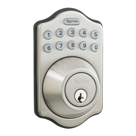
- Page 1 CONCIERGE 100 PROFESSIONAL SERIES ELECTRONIC DEADBOLT USER GUIDE...
-
Page 2: Table Of Contents
CONTENTS IMPORTANT SAFETY INFORMATION TOOLS NEEDED FOR NEW INSTALLATION COMPONENTS OF ELECTRONIC KEYPAD DEADBOLT DOOR PREPARATION 4 - 7 INSTALLATION 8 - 13 OVERVIEW OF FUNCTIONS KEYPAD LIGHTS & WARNINGS CODES INFORMATION PROGRAMMING 1. AUTOMATIC BOLT DIRECTION ADJUSTMENT 2. CHANGE PROGRAMMING CODE 3. ADD/DELETE USER ENTRY CODE 4. DELETE ALL USER ENTRY CODES AT ONCE 5. TEMPORARILY DISABLE ALL USER CODES 6. CREATE A DISPOSABLE USER ENTRY CODE 7. “AUTO LOCK” FUNCTION 8. MUTE ON/OFF 9. RESTORE FACTORY SETTING OPERATION... -
Page 3: Important Safety Information
1. Do not use any abrasives or any chemical products containing any substance of alcohol, benzene, hydrochloric acid or nitric acid, and avoid sharp or scratching objects to clean this lockset. 2. Do not let any water or liquid into lockset during installation process. IMPORTANT SAFETY INSTRUCTION 1. Do not attempt to disassemble any internal components of the lockset personally. You may run the risk of voiding the limited warranty. 2. Do not drop or hit the lockset. 3. Do not use sharp objects to press key buttons. 4. Always create a backup of information you want to keep (such as programming code and use codes). Please use the last page of this booklet as your reference. 5. Please change programming code before operating this lockset. CARE AND MAINTENANCE The following care instructions should be followed to ensure a long lasting finish: 1. Remove locks, or do not install locks, prior to painting your door. 2. Periodically clean with mild soap and a soft cloth only. ® REGISTERED TRADEMARK OF TAYMOR INDUSTRIES LTD. -
Page 4: Tools Needed For New Installation
TOOLS NEEDED FOR NEW INSTALLATION • PENCIL • CHISEL • TAPE MEASURE • HAMMER • PHILLIPS SCREWDRIVER • 1” (25 mm) & 1/8” (3 mm) DRILL BITS • 2-1/8” (54 mm) HOLE BORING KIT • POWER DRILL • 2” (51 mm) 6D COMMON NAIL • 4 - AA 1.5V ALKALINE BATTERIES ® REGISTERED TRADEMARK OF TAYMOR INDUSTRIES LTD. -
Page 5: Components Of Electronic Keypad Deadbolt
COMPONENTS OF ELECTRONIC KEYPAD DEADBOLT INTERIOR BATTERY COVER WOOD SCREWS RUBBER GASKET INTERIOR ASSEMBLY LATCH MOUNTING PLATE WOOD CYLINDER SCREWS TORQUE MOUNTING BLADE BOLTS IC WIRE METAL SCREWS CYLINDER EXTERIOR ASSEMBLY ® REGISTERED TRADEMARK OF TAYMOR INDUSTRIES LTD. -
Page 6: Door Preparation
DOOR PREPARATION MARK DOOR WITH TEMPLATE (ATTACHED SEPARATELY) Note: If replacing an existing lock or installing in a pre-drilled door, begin with page 8. a. Use TEMPLATE to mark centerline on door for deadbolt about 3” to 6” (75 mm to 150 mm) above the existing knob or lever. b. Stand so door swings towards you. Align template on centerline and fold template as shown. TEMPLATE CENTERLINE MARK DOOR EDGE APPROXIMATELY 3” TO 6” (75 mm TO 150 mm) ABOVE THE ENTRY KNOB OR LEVER ® REGISTERED TRADEMARK OF TAYMOR INDUSTRIES LTD. - Page 7 DOOR PREPARATION MARK AND DRILL PILOT HOLES Select backset. Mark and drill pilot holes as shown. CENTERLINE 2-1/8” (54 mm) 1” (25 mm) BACKSET DRILL 1/8” (3 mm) PILOT HOLE DRILL 1/8” (3 mm) PILOT HOLE ® REGISTERED TRADEMARK OF TAYMOR INDUSTRIES LTD.
- Page 8 DOOR PREPARATION USING THE TEMPLATE MARKS AS A GUIDE a. Drill a 2-1/8” (54 mm) hole on the door face from both sides to prevent wood from splitting. b. Drill a 1” (25 mm) hole in the door edge for the latch. c. Use the latch faceplate as a pattern for the mortise and pilot holes. Chisel 1/8” (3 mm) deep. Faceplate should fit flush. Note: for drive-in latch, simply insert latch. 1” 2-1/8” (25 mm) CHISEL 1/8” (54 mm) (3 mm) DEEP FACEPLATE OUTLINE ® REGISTERED TRADEMARK OF TAYMOR INDUSTRIES LTD.
- Page 9 DOOR PREPARATION PREPARE DOOR JAMB AND INSTALL STRIKE PLATE a. To identify the center of the strike: insert the latch, close the door; using the latch faceplate as a guide, mark horizontal centerline and outline of the strike. Ensure the center of the faceplate and the center of the strike are aligned. b. Chisel 5/64” (2 mm) deep along the strike outline to allow the strike to be aligned with the door frame. c. Insert the strike and tighten it with wood screws. Door jamb hole dimension a. 1-3/16 (30 mm) b. 1-3/8” (35 mm) c. 1” (25 mm) Strike dimension d. 9/32” (7 mm) e. 2-15/16” (75 mm) f. 1-5/16” (33 mm) ® REGISTERED TRADEMARK OF TAYMOR INDUSTRIES LTD.
-
Page 10: Installation
INSTALLATION 6 WAY LATCH 6 WAY LATCH Latch Backset Adjustment To Change Latch Faces To rotate the latch case as following 1. Use a flat-head screwdriver to separate illustration for backset 2-3/4” (70 mm) the faceplate form the backplate. or reverse direction for 2-3/8” (60 mm) 2. Snap the selected faceplate onto the backplate. 2-3/4” (70 mm) Drive-in Installation Make sure the round faceplate is properly aligned as illustrated and snap it to the latch case. DRIVE-IN LATCH ® REGISTERED TRADEMARK OF TAYMOR INDUSTRIES LTD. - Page 11 INSTALLATION INSTALL LATCH IN MORTISED AREA OR DRIVE-IN LATCH If your door is set up to use a standard type latch, please install it with the 3/4” (20 mm) screws that are provided. If you use the drive-in latch, please tap it into place. DRIVE-IN LATCH LATCH FLUSH BACKSET WOOD BLOCK (NOT INCLUDED) FACEPLATE 3/4” (20 mm) WOOD SCREWS ® REGISTERED TRADEMARK OF TAYMOR INDUSTRIES LTD.
- Page 12 INSTALLATION a. Make sure latch is in retracted position. b. Insert the cylinder into exterior assembly with cylinder torque blade inserted through hub of the latch in a horizontal position. c. Pass the IC wire under the latch to the interior side of the door. IC WIRE ® REGISTERED TRADEMARK OF TAYMOR INDUSTRIES LTD.
- Page 13 INSTALLATION INSTALL INSIDE THE MOUNTING PLATE KEEP PARALLEL a. Carefully pass the IC wire through the wire hole on the mounting plate. b. Making sure that the exterior assembly and cylinder are pressed flush against the exterior door, insert the mounting bolts and tighten. c. Check the vertical alignment for the mounting plate and exterior assembly. d. Test. Using the key, retract and extend the bolt MOUNTING PLATE a few times to test for smooth action. e. If action feels rough, loosen screws and realign the mounting plate and exterior assembly. MOUNTING BOLTS IC WIRE ® REGISTERED TRADEMARK OF TAYMOR INDUSTRIES LTD.
- Page 14 INSTALLATION - DOOR HANDING IDENTIFY THE DOOR HANDING a. Face the door from inside b. The door is “left-handed” if the hinges are on the left hand side of the door. c. The door is “right-handed” if the hinges are on the right hand side of the door. INTERIOR HINGE DOOR LEFT-HANDED RIGHT-HANDED EXTERIOR ADJUST INTERIOR TURN PIECE a. Turn the turn piece to the left when it is a “right-handed” door. b. Turn the turn piece to the right when it is a “left-handed” door. ® REGISTERED TRADEMARK OF TAYMOR INDUSTRIES LTD.
- Page 15 INSTALLATION - RECEIVER MODULE INSTALL RECEIVER MODULE a. Remove the battery cover (push it up and pull it out). b. Connect the IC wires and ensure the cylinder torque blade is engaged with the turn piece then attach the interior assembly to the door with the metal screws. c. Insert 4 (AA) 1.5V alkaline batteries and place the cover back onto the interior assembly. BATTERY COVER WOOD SCREWS METAL SCREWS ® REGISTERED TRADEMARK OF TAYMOR INDUSTRIES LTD.
-
Page 16: Overview Of Functions
OVERVIEW OF FUNCTIONS 1. PROGRAMMING BUTTON Programming Button is for entering codes, clearing errors, and setting functions. It’s also a “Lock” Button. 2. KEYPAD WITH NUMBER BUTTONS For inputting codes, 4-10 digits in length. 3. CYLINDER Retract/Expand latch bolt by key from outside. 4. RUBBER GASKET To prevent water leaking through exterior assembly. 5. BATTERY COVER 6. BATTERY HUB Four (AA) Alkaline Batteries (sold separately) 7. “R” BUTTON (RESET) Restore default setting 8. TURN PIECE Retract/Expand the latch bolt from inside. ® REGISTERED TRADEMARK OF TAYMOR INDUSTRIES LTD. -
Page 17: Keypad Lights & Warnings
1. One “Beep” - operating function was performed properly. 2. Two “Beeps” - programming function was performed properly. 3. Three “Beeps” - operating function was not performed properly. LOW BATTERY WARNING LED indicator flashes “Red” and constant “Beep” sound is on for 10 seconds. Please replace batteries. Note: • The lock can still be operated via regular key. • All settings are stored in the memory and will not be affected even when the batteries are replaced. ® REGISTERED TRADEMARK OF TAYMOR INDUSTRIES LTD. -
Page 18: Codes Information
CODE INFORMATION PROGRAMMING CODE 1. Programming code provides ability to program/reprogram the deadbolt, and change/delete/add individual user codes. 2. Programming code cannot be used to unlock the deadbolt. 3. Only one programming code is allowed, 4-10 digits in length. 4. The factory preset programming code is 0-0-0-0, and can be changed anytime if needed. USER ENTRY CODE 1. User entry code allows the individual user to lock and unlock the deadbolt. 2. The factory preset user entry code is 1-2-3-4. Please delete it and create your personal, unique user entry code as soon as the deadbolt is installed. 3. User entry code can be 4-10 digits in length. 4. Maximum of 6 user entry codes can be programmed into one deadbolt. 5. An individual user entry code can be changed/deleted/added to the lockset only by using a valid programming code. ® REGISTERED TRADEMARK OF TAYMOR INDUSTRIES LTD. -
Page 19: Programming
PROGRAMMING AUTOMATIC BOLT DIRECTION ADJUSTMENT Deadbolt throw direction is automatically adjusted to left or right-handed door. 1. Deadbolt should be in unlocked position. 2. Make sure the interior thumbturn position is identified properly according to door handing. (see page 12). FUNCTION STEPS Enter Press Detect Left/Right Hand Programming “0” Door Installation Code ® REGISTERED TRADEMARK OF TAYMOR INDUSTRIES LTD. -
Page 20: Change Programming Code
1. Deadbolt should be in unlocked position. 2. LED indicator flashes “Orange” while in programming mode. LED indicator flashes “Green” twice with 2 long “Beeps” when programming function is performed correctly. LED indicator light flashes three times with three “Beeps” when programming function is performed incorrectly. Note: wait for at least 6 seconds or press and repeat programming steps if programming error was committed. 3. Every programming step should be performed in 6 seconds or less. FUNCTION STEPS Change Enter Enter Press Programming Programming Programming “4” Code Code Code ® REGISTERED TRADEMARK OF TAYMOR INDUSTRIES LTD. -
Page 21: Add/Delete User Entry Code
PROGRAMMING ADD/DELETE USER ENTRY CODE 1. User entry codes can be deleted individually. You can reuse the same number as a code even if it was deleted before. 2. The factory preset user entry code is 1-2-3-4. Please delete it and create your personal unique user entry code once the deadbolt is installed. FUNCTION STEPS Enter Enter New Press Add New User Programming User Entry “1” Entry Code Code Code Enter User Enter Press Delete Existing Entry Code Programming “2” User Entry Code you want Code to delete ® REGISTERED TRADEMARK OF TAYMOR INDUSTRIES LTD. -
Page 22: Delete All User Entry Codes At Once
PROGRAMMING DELETE ALL USER ENTRY CODES AT ONCE 1. All user entry codes can be deleted at once. You can still reuse the same numbers as new codes even if they have been deleted before. 2. “Auto-Lock” and “Keypad Lock” functions will be invalid after deleting all user entry user entry codes, and the deadbolt can only be operated by regular key. The functions will be restored when the new user entry codes are created. FUNCTION STEPS Enter Press Delete all User Entry Programming “3” Codes at once Code ® REGISTERED TRADEMARK OF TAYMOR INDUSTRIES LTD. -
Page 23: Temporarily Disable All User Codes
PROGRAMMING TEMPORARILY DISABLE ALL USER CODES 1. “Auto-Lock” and “Keypad Lock” functions will be invalid when all user entry codes are temporarily disabled. The deadbolt can only be operated by regular key at this time. 2. Repeat the programming steps to restore all user entry codes. FUNCTION STEPS Enter Press Disable/Enable all Programming “8” User Entry Codes Code ® REGISTERED TRADEMARK OF TAYMOR INDUSTRIES LTD. -
Page 24: Create A Disposable User Entry Code
PROGRAMMING CREATE A DISPOSABLE USER ENTRY CODE 1. Disposable entry code can only be used once. 2. You can reuse the same number as a disposable user entry code again. FUNCTION STEPS Create Enter Enter New Press Disposable User Programming Disposable “9” Entry Code Code Entrly Code ® REGISTERED TRADEMARK OF TAYMOR INDUSTRIES LTD. -
Page 25: "Auto-Lock" Function
PROGRAMMING “AUTO-LOCK” FUNCTION 1. The door will be automatically locked within 10 to 99 seconds when “Auto-Lock” function is enabled. 2. The deadbolt comes with “Auto-Lock” function disabled from the factory. 3. “Auto-Lock” time delay is preset to 30 seconds. It can be adjusted to 10 to 99 seconds if needed. 4. The system will signal an operating error if the deadbolt fails to latch properly. Re-enter valid user entry code to unlock the door and retract the latchbolt. “Auto-Lock” function is now restored. FUNCTION STEPS Enter Press Auto-Lock Programming “5” ON/OFF Code Enter Enter Press Auto-Lock Seconds Programming “6” Time Delay (10 to 99) Code ® REGISTERED TRADEMARK OF TAYMOR INDUSTRIES LTD. -
Page 26: Mute On/Off
PROGRAMMING MUTE ON/OFF 1. Audible “Beep” alerts when pressing keypad buttons, during programming or operating errors, can be turned off if needed. 2. LED indicator light will still function when muted. 3. Motor operating sound cannot be muted. FUNCTION STEPS Enter Press Mute Programming “7” ON/OFF Code ® REGISTERED TRADEMARK OF TAYMOR INDUSTRIES LTD. -
Page 27: Restore Factory Setting
PROGRAMMING RESTORE FACTORY SETTING 1. Remove battery cover and locate “R” button. 2. Press “R” button for at least 5 seconds until you hear three long “Beeps”. 3. The deadbolt is now reset back to the factory setting: - programming code 0-0-0-0 - user entry code 1-2-3-4 4. Repeat automatic bolt direction adjustment (see page 17) before you proceed to programming any other functin into the deadbolt. ® REGISTERED TRADEMARK OF TAYMOR INDUSTRIES LTD. -
Page 28: Operation
OPERATION LOCK OPERATION TO LOCK 1. Press or use regular key to lock the deadbolt from outside. 2. Turn thumbturn piece to lock the deadbolt from inside. TO UNLOCK 1. Enter valid user entry code and press , or use regular key to unlock the deadbolt from the outside. 2. Turn thumbturn piece to unlock the deadbolt from the inside. ® REGISTERED TRADEMARK OF TAYMOR INDUSTRIES LTD. - Page 29 OPERATION SECURITY MODE 1. The keypad will be automatically deactivated for 45 seconds after 5 unauthorized entry attempts. 2. The deadbolt can be locked and unlocked by the regular key under security mode. ® REGISTERED TRADEMARK OF TAYMOR INDUSTRIES LTD.
-
Page 30: Troubleshooting Guide
TROUBLESHOOTING GUIDE - INSTALLATION QUESTIONS ANSWERS A. I just completed the 1. Check the alignment between the strike hole and the latch to ensure installation, but am there is unobstructed movement of the latchbolt. unable to operate it 2. Make sure the torque blade is properly inserted into the latch hub in manually. What should a horizontal position. I do? 3. Repeat the Automatic Bolt Direction routine (see page 17). B. Sometimes when I operate the lock 1. The electromechanical components of the lockset are out of sync. manually I “feel” a To re-synchronize the system please “lock” and then “unlock” the bump while turning the deadbolt using the keypad. thumbturn or key. C. In am pressing any 1. Check to see if the batteries are properly installed. button on the keypad 2. Re-install new batteries if the “Low Battery Warning” is on. and it doesn’t seem to 3. Check for proper connection between the IC wires. respond at all. ® REGISTERED TRADEMARK OF TAYMOR INDUSTRIES LTD. - Page 31 TROUBLESHOOTING GUIDE - OPERATION QUESTIONS ANSWERS A. I’m not able to change 1. Make sure that every programming step is completed in under 6 the programming code. seconds. B. What type of batteries 1. For best results, please use new non-rechargeable alkaline batter- do you recommend? ies. (4 - AA 1.5V) C. How long will the lock 1. Based on 15 operations per day, a single set of alkaline batteries operate on one set of will operate the lockset for over a year. batteries? ® REGISTERED TRADEMARK OF TAYMOR INDUSTRIES LTD.
-
Page 32: Information Page
INFORMATION PAGE IMPORTANT NOTE: 1. Do not share your programming code with anyone else. 2. Keep a written copy of all valid user codes in a safe place. (You may use the table below to record your information) 3. You are advised to re-program all codes if you lost any security information in the table. NAME USER CODE PROGRAMMING CODE ® REGISTERED TRADEMARK OF TAYMOR INDUSTRIES LTD. -
Page 33: Warranty
CONCIERGE 100 PROFESSIONAL SERIES ELECTRONIC DEADBOLT WARRANTY Taymor’s CONCIERGE 100 PROFESSIONAL SERIES ELECTRONIC DEADBOLT is manufactured under the highest standards of quality and workmanship. Taymor Locks are warranted to be free from finish defects for 5 (five) years and free from mechanical, material and workmanship defects to the original consumer purchaser for the life of the product as long as the original owner owns his/her home. Taymor will replace free of charge, during the warranty period, any part that fails to meet the warranty under normal installation and use as long as the product has been cared for according to the care instructions listed in the package and on the website. Electronic components of this lock are limited to 1 (one) year from the date of purchase.
Need help?
Do you have a question about the CONCIERGE 100 and is the answer not in the manual?
Questions and answers
My Concierge 100 has had batteries changed a few time, but this time the numbers won't work afterward. I know it has power, it beeps when I lock and unlock with the manual knob, but the numbers don't light up or operate.
If the numbers on a Taymor Concierge 100 do not light up or operate after changing the batteries, possible issues include:
1. Batteries may not be properly installed — check battery orientation.
2. Batteries could be low or defective — try replacing with new non-rechargeable alkaline AA 1.5V batteries.
3. The system may need to be re-synchronized — lock and then unlock the deadbolt using the thumbturn or key.
This answer is automatically generated
I changed the batteries, the buttons don't work. I get 2 pips when I lock the deadbolt manually, 1 pip when I unlock manually
The Taymor Concierge 100 deadbolt giving 2 pips when locked manually and 1 pip when unlocked manually indicates that the electromechanical components are out of sync. To re-synchronize the system, manually lock and then unlock the deadbolt using the keypad, thumbturn, or key.
This answer is automatically generated