Table of Contents
Advertisement
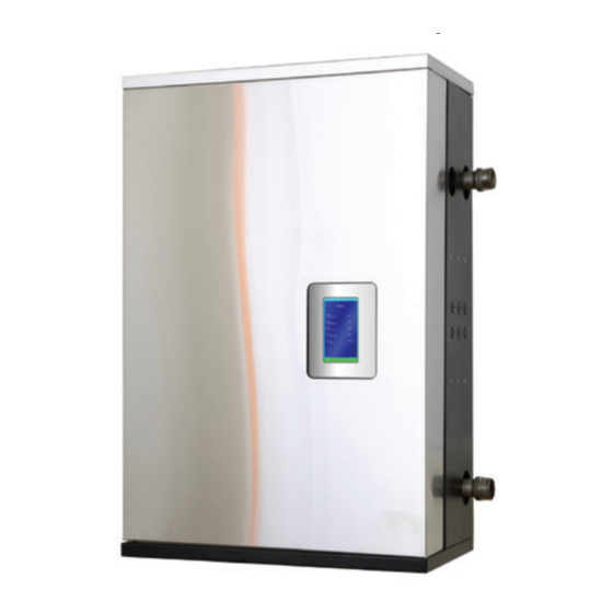
VFC 15-150, VFC 45-225
MODULATING GAS BOILERS
WARNING: If the information in this manual is not followed exactly, a fire or
explosion may result causing property damage, personal injury, or loss of life.
Do not store or use gasoline or other flammable vapours and liquids or other
combustible materials in the vicinity of this or any other appliance.
WHAT TO DO IF YOU SMELL GAS:
• Do not try to light any appliance.
• Do not touch any electrical switch; do not use any phone in your building.
• Immediately call your gas supplier from a nearby phone. Follow the gas
supplier's instructions.
• If you cannot reach your gas supplier, call the fire department.
Installation and service must be performed by a qualified installer, service
agency or the gas supplier.
This Manual is also available in French - contact IBC or visit our web site www.ibcboiler.com
(Natural Gas or Propane)
www.ibcboiler.com
Advertisement
Table of Contents
Troubleshooting

Related Manuals for IBC VFC 15-150


Summary of Contents for IBC VFC 15-150
- Page 1 • If you cannot reach your gas supplier, call the fire department. Installation and service must be performed by a qualified installer, service agency or the gas supplier. This Manual is also available in French - contact IBC or visit our web site www.ibcboiler.com www.ibcboiler.com...
-
Page 2: Safety Considerations
BEST PRACTICES Points out recommendations for better installation. Supplied with the boiler - The IBC boiler is shipped with an accessory parts kit consisting of the following items: • 1 x Vent connection kit •... -
Page 3: Specifications
VFC 15-150, VFC 45-225 MODULATING GAS BOILERS SPECIFICATIONS SPECIFICATION VFC 15-150 VFC 45-225 CSA Input (Natural Gas or Propane) - MBH 15 - 150 45 - 225 CSA Input (Natural Gas or Propane) - kW 4.4 - 44 13 - 66... - Page 4 VFC 15-150, VFC 45-225 MODULATING GAS BOILERS THIS PAGE INTENTIONALLY LEFT BLANK INSTALLATION AND OPERATION INSTRUCTIONS...
-
Page 5: Table Of Contents
DIAGRAMS ............6-1 VFC 15-150 PARTS DIAGRAMS ........6-2 VFC 45-225 PARTS DIAGRAMS . - Page 6 VFC 15-150, VFC 45-225 MODULATING GAS BOILERS The Installer must carefully read this manual to ensure that all installation DANGER details can be adhered to. Special attention is to be paid to clearances and access, vent travel and termination, gas supply, condensate removal and Should overheating occur combustion air supply.
-
Page 7: Installation
Gas Inlet 1/2" NPT-F Knock-outs (6) 1/2" Touch Screen Display 2-1/4” x 4” Exhaust Vent 4.0" Hole Combustion Air 4.0" Hole Table 1: Connections Figure 1a: Dimensions / Connections for VFC 15-150 Figure 1b: Dimensions / Connections for VFC 45-225 INSTALLATION... -
Page 8: Code Requirements
VFC 15-150, VFC 45-225 MODULATING GAS BOILERS CODE REQUIREMENTS The VFC 15-150 and VFC 45-225 boiler models were tested to and certified under CSA 4.9-2014 / ANSI Z21.13-2014. Installation must conform to local codes, or in the absence of these, with the latest editions of CAN/CGA B149.1 and the Canadian Electrical Code Part 1 CSA... -
Page 9: Exhaust Venting And Air Intake
VFC 15-150, VFC 45-225 MODULATING GAS BOILERS sources. Do not seal boiler case openings directly when firing - allow for WARNING air circulation and ventilation in the immediate area. Exposed water piping and associated components DISTANCE FROM RECOMMENDED (relief valves, circulators, etc.) - Page 10 VFC 15-150, VFC 45-225 MODULATING GAS BOILERS determine there is no blockage or restriction, leakage, corrosion and other deficiencies which could cause an unsafe condition. • Insofar as is practical, close all building doors and windows and all doors between the space in which the appliances remaining connected to the common venting system are located and other spaces of the building.
- Page 11 (see Figure 2). • for PPs, use IBC’s VFC PPs transition kit as appropriate for the chosen PPs system: CENTROTHERM INNOFLUE™...
- Page 12 CPVC or PPs (Rigid Single Wall) piping is the standard venting option; with this, the VFC 15-150 boiler, for example, can be sited up to 50 equivalent feet from the vent termination using 2” or up to 120’ using 3”. The actual vent travel allowance is reduced for fittings in accordance with Table 4.
- Page 13 VFC 15-150, VFC 45-225 MODULATING GAS BOILERS Exhaust venting must slope down to the trap/drain with a pitch of at least 1/4" per WARNING foot (PPs vent: follow PPs manufacturer requirements for slope) so condensate runs towards the trap. Support should be provided for intake and vent piping, Fill trap with water before particularly so for horizontal runs (follow local code).
- Page 14 • Confirm material meets local codes including fire stopping requirements. • Pipe clearances - no IBC requirements, but best practice allows a minimum 1/4” gap around pipes to prevent binding and expansion noise; follow local codes. • All piping must be liquid and pressure tight.
- Page 15 VFC 15-150, VFC 45-225 MODULATING GAS BOILERS 1.4.6 Sidewall Vent Termination Sidewall direct vent applications shall be vented as follows: • Both the inlet and exhaust terminations should normally be located on the same plane (side) of the building. •...
- Page 16 VFC 15-150, VFC 45-225 MODULATING GAS BOILERS For side venting of multiple boiler sets, group all intake terminals together with 4" to 8" lateral spacing, and similarly group the exhaust pipes. Place the 2 groups on the same plane of the building (e.g. north facing wall). Place the 2 groups of pipes at least 3' apart (the closest intake and exhaust pipes shall be 36"...
- Page 17 VFC 15-150, VFC 45-225 MODULATING GAS BOILERS 1.4.7 “Direct Vent” Combustion Air Intake Piping WARNING There are two basic methods of supplying combustion air to an IBC boiler. In addition to preventing ingestion of chemical The direct vent option uses piping from the outside to supply combustion air contaminants, care must directly to the boiler’s combustion air connection.
- Page 18 VFC 15-150, VFC 45-225 MODULATING GAS BOILERS Combustion air piping is connected at the base of the boiler using a standard 2” PVC (ABS) coupler or elbow and run horizontally or vertically to the outdoors. Screen material can be placed at the inlet as appropriate for the environment (e.g.
-
Page 19: Closet Installations
If combustion air contamination from ingested particulate matter may be a NOTE concern in any installation, an optional air intake filter may be installed. IBC supplied air intake filters have a known pressure drop and fouling factor and Combustion fan... -
Page 20: Condensate Removal
VFC 15-150, VFC 45-225 MODULATING GAS BOILERS CONDENSATE REMOVAL IBC’s specified vent configuration promotes the safe drainage of moisture from the boiler and exhaust venting without flowing liquids back through the heat exchanger (as done by other condensing boilers). Reliable system operation requires (1) proper design and installation of exhaust venting to allow condensate to run back to the drain/trap;... - Page 21 Do not place the drain connection tee directly at the base of the boiler. 1.5.1.2 WITH PPS VENTING SYSTEMS For connection to PPS venting systems, an IBC VFC PPs transition kit is required; select the kit corresponding to the brand of PPs venting to be used at the installation site (see page 1-5).
- Page 22 VFC 15-150, VFC 45-225 MODULATING GAS BOILERS Figure 17: Condensate trap installation - PPs Figure 18: IBC Kit #P-166A for Centrotherm PPs (with Centrotherm clips – IBC #180-050) 1-16 INSTALLATION AND OPERATION INSTRUCTIONS...
- Page 23 VFC 15-150, VFC 45-225 MODULATING GAS BOILERS Figure 19: IBC Kit #P-167A for M&G Duravent PPs (with M&G Duravent clips – IBC #180-051) Each manufacturer of PPs venting systems has its own unique design for their metal retaining clips. While they may look very similar, do not mix any such components between suppliers.
- Page 24 Confirm the Drain Spout Compression Nut (E) is secure by applying 10 lbs WARNING of downward force on the trap body (D). Then apply IBC #152-004 Reusable Strap as shown in Figure 17 to prevent blow-off of the trap during any The Trap Hook reusable delayed ignition event.
- Page 25 VFC 15-150, VFC 45-225 MODULATING GAS BOILERS WARNING If condensates are to be discharged into building drain piping materials that are subject to corrosion, a neutralization package must be used. CAUTION When a condensate neutralization package is installed, the pH of the...
-
Page 26: Water Piping
VFC 15-150, VFC 45-225 MODULATING GAS BOILERS WATER PIPING WARNING 1.6.1 General Piping Issues During operation, the relief The VFC modulating series boilers are designed for use within a closed loop, valve may discharge large forced circulation, low pressure system. A 30 psi pressure relief valve (3/4" NPT) amounts of steam and/or hot is supplied for field installation in the flow supply line –... - Page 27 VFC 15-150, VFC 45-225 MODULATING GAS BOILERS Do not place any water connections overhead the boiler; leaks can damage the fan & controls. If needed, create a shield over the louvered top of the cover, but allow clearance for airflow and service access.
- Page 28 VFC 15-150, VFC 45-225 MODULATING GAS BOILERS The VFC modulating series boilers are designed to supply up to four different WARNING heating loads with temperatures within the range 34°F to 185°F - to meet three separately piped loads. Use closely spaced tees to connect each pumped “load”...
- Page 29 VFC 15-150, VFC 45-225 MODULATING GAS BOILERS PRESSURE VESSEL HEAD Flow rate (gpm) Head @ flow (ft wc) 12.3 NOTE Table 6: Pressure Vessel Head The Primary (boiler) pump Ensure the pump is rated for the design circulating water temperatures; some pumps...
- Page 30 VFC 15-150, VFC 45-225 MODULATING GAS BOILERS 1.6.2 Installation Rules NOTE: The Boiler Trim element – common to each of the following systems - includes the pressure relief, fill, expansion tank and air bleed elements. The primary pump can be located on either the Supply or Return piping sections.
- Page 31 (4 gpm for the 15-150, 8 gpm for the 45-225). Representative). For further information and details, consult our Application Notes – which provide detail on specific single and multiple boiler applications “Piping”, “Wiring” and “Settings”. (available at www.ibcboiler.com or from your IBC Representative). 1-25 INSTALLATION...
-
Page 32: Gas Piping
VFC 15-150, VFC 45-225 MODULATING GAS BOILERS GAS PIPING The boiler requires an inlet gas pressure of at least 3.0" w.c. for natural gas or NOTE propane. For either fuel, the inlet pressure shall be no greater than 14.0" w.c. -
Page 33: Electrical Connections
VFC 15-150, VFC 45-225 MODULATING GAS BOILERS ELECTRICAL CONNECTIONS All Electrical wiring to the boiler (including grounding) must conform to local electrical codes and/or National Electrical Code, ANS/NFPA No. 70 – latest edition, or The Canadian Electrical Code, C22.1 - Part 1. - Page 34 Thermister - type with a resistance of 10,000 ohms at 25°C and β = 3892. We do stealing thermostats. See the not recommend using 3rd party supplied sensors. Compatible water temperature Wiring Diagram for details. sensors and outdoor sensors can be supplied by your IBC distributor. 1-28 INSTALLATION AND OPERATION INSTRUCTIONS...
-
Page 35: Thermostat Heat Anticipator
VFC 15-150, VFC 45-225 MODULATING GAS BOILERS 1.8.6 Thermostat Heat Anticipator IBC “Therm.” contacts draw no power, so an anticipator setting for the thermostat is not applicable with the VFC modulating series boilers. In the case of a single temperature / heat load where zone valves are used to manage individual thermostatically controlled zones, each room thermostat’s heat anticipator should... - Page 36 VFC 15-150, VFC 45-225 MODULATING GAS BOILERS THIS PAGE INTENTIONALLY LEFT BLANK 1-30 INSTALLATION AND OPERATION INSTRUCTIONS...
-
Page 37: Ibc Boiler Control
Load Combining – simultaneous operation of 2 similar water temperature loads • The control can manage and/or operate in a network of up to 24 IBC VFC or SL boilers Some of the new features available in the touch screen control include: •... -
Page 38: Control Interface
VFC 15-150, VFC 45-225 MODULATING GAS BOILERS Operational and historical data may be accessed at any time using the System Status and Load Profiles sections of the control. Error logs are available in the Diagnostics section and the controller is capable of recording any or all errors since original power-up complete with the date and time of the error. -
Page 39: Startup And Commissioning
VFC 15-150, VFC 45-225 MODULATING GAS BOILERS STARTUP AND COMMISSIONING 3.1 LIGHTING AND SHUTTING DOWN THE BOILER STARTUP AND COMMISSIONING... -
Page 40: Prior To Start-Up
Manifold pressure test port de-ration. The boiler will automatically de-rate at altitudes above 4,500 feet. Refer to the IBC Altitude tables for further information. DANGER To verify the proper operation of the gas valve in the field, the following procedure Making adjustments to can be carried out by a qualified technician (see Figure 32). - Page 41 VFC 15-150, VFC 45-225 MODULATING GAS BOILERS procedure. Pressure may droop up to 1” to 2” w.c. at high fire but under no circumstances should it drop below 3” w.c. at the gas valve inlet test port. Allow the boiler to ignite / run against a large load, to maintain high fire With the boiler at maximum output, use a 2 mm hex key to adjust the zero- offset (see Figure 32, “A”) as required to achieve -0.2 to -0.3”...
- Page 42 VFC 15-150, VFC 45-225 MODULATING GAS BOILERS Figure 32: Gas Valve and Pressure Reference System INSTALLATION AND OPERATION INSTRUCTIONS...
-
Page 43: Fuel Conversion
VFC 15-150, VFC 45-225 MODULATING GAS BOILERS FUEL CONVERSION WARNING The VFC Series modulating boiler is factory fire-tested to operate with natural gas, or propane as ordered. The rating plate will be marked to indicate which fuel Check the rating plate of the particular boiler has been set up with. - Page 44 VFC 15-150, VFC 45-225 MODULATING GAS BOILERS THIS PAGE INTENTIONALLY LEFT BLANK INSTALLATION AND OPERATION INSTRUCTIONS...
-
Page 45: Maintenance
VFC 15-150, VFC 45-225 MODULATING GAS BOILERS MAINTENANCE BOILER MAINTENANCE 4.1.1 General Care CAUTION • Keep combustible materials and flammable liquids and vapours away from the The owner is responsible for boiler. general care of the boiler. • Keep vent terminals clear of obstructions (snow, dirt, etc.). -
Page 46: Heat Exchanger
(e.g. 10°F between supply and return when Care should be taken to firing at 75,000 Btu/hr. for a VFC 15-150 unit). avoid disturbing or damaging the refractory. If damage 4.1.8 Gas Piping occurs, contact the factory for directions. -
Page 47: Boiler Treatment
VFC 15-150, VFC 45-225 MODULATING GAS BOILERS 4.1.12 Boiler Treatment WARNING • Check consistency of any boiler treatment used (e.g. Furnox™), for Do not use automotive-type appropriate mixture. Chemical inhibitors are consumed over time, lowering ethylene or other types of their density. -
Page 48: Component Description
IBC # 180-022 zero governor gas valve provides strict gas/air mixture control over FUNCTION: the range — 15 - 150 MBH for VFC 15-150 or 45 – 225 MBH for VFC 45-225. see Section 3.3 - Commissioning, for gas valve adjustments INSTALLATION: 4.2.3 Direct Spark Ignition Module... -
Page 49: Water Pressure Sensor
Place fingers on the board edge only when handling. There is a 3V lithium battery (IBC # 240-024) for powering the permanent memory if AC power is not connected. -
Page 50: Gaining Access To Combustion Chamber, Burner Removal Instructions; Fan And Gas Valve Removal Instructions
Release the v-clamp, taking care to preserve its gasket for possible reuse. For the VFC 15-150, remove the 4 x 6mm hex socket bolts at the FC: Fan interface. Three of the 4 bolts are easily dealt with using a regular 6mm Allen key, while the upper (rear) fastener is in a confined space;... - Page 51 VFC 15-150, VFC 45-225 MODULATING GAS BOILERS angle-driver to reach past the gas valve, or a stubby Phillips screwdriver for enhanced working space. Three vinyl hoses do not need to be disconnected, but if that is chosen ensure they are marked for reinstallation. Avoid placing pressure on the disk-shaped air pressure sensor, which can damage the sensor.
- Page 52 VFC 15-150, VFC 45-225 MODULATING GAS BOILERS For option 3 – install the 4 small Phillips screws through the gas valve support bracket and into the gas valve adjacent to the gas inlet. The screws are to be loosely attached at this stage to allow easier alignment at step 7.
-
Page 53: Troubleshooting
VFC 15-150, VFC 45-225 MODULATING GAS BOILERS 5.0 TROUBLESHOOTING The troubleshooting section is divided into 3 sections: 5.1 Preliminary Checks 5.2 Electronic Components 5.3 Troubleshooting Guide Often, a problem can be identified and solved through simple checks of the basics: confirming the electrical power supply, gas flow and resetting the thermostat control. -
Page 54: Electronic Components
VFC 15-150, VFC 45-225 MODULATING GAS BOILERS ELECTRONIC COMPONENTS This section details the method for troubleshooting the non-standard electronic components on the boiler including the electronic differential air pressure sensor and the temperature sensors. 5.2.1 Temperature Sensors The resistance of the temperature sensors varies inversely with temperature. To... - Page 55 If the Differential Air Pressure Sensor replacement is required, ensure the replacement sensor is IBC part# 240-003 (and specifically that it is not a similar- looking part marked for use only on the SL 28-160 model boiler). Use of any other differential air pressure sensor is forbidden.
- Page 56 (above red - Maximum ignition trials error”, and Section 5.3.2 - “Ignition problems”). For L.E.D.) conversion from Fenwal to the Capable Control, specify IBC part# 240-049 – that provides the module plus added wire lead and instructions. INSTALLATION AND OPERATION INSTRUCTIONS...
-
Page 57: Troubleshooting Guide
VFC 15-150, VFC 45-225 MODULATING GAS BOILERS 5.3 TROUBLESHOOTING GUIDE 5.3.1 Using Control Module Errors Displayed SYMPTOM DIAGNOSIS REMEDY AIRFLOW ERROR Check fan operation • Check lead is attached at fan. • Cycle power off/on; listen for fan initialization. Touch Screen Message: If no action, focus your attention on the fan itself. - Page 58 VFC 15-150, VFC 45-225 MODULATING GAS BOILERS SYMPTOM DIAGNOSIS REMEDY MAXIMUM IGNITION TRIALS No spark when Check that igniter lead is secure at the control ERROR igniting. Igniter module and at the probe. probe/flame sensor Touch Screen Message: disconnected. Error – Ignition Failure after 3 Manual gas shutoff is Check for gas flow.
-
Page 59: Ignition Problems
VFC 15-150, VFC 45-225 MODULATING GAS BOILERS SYMPTOM DIAGNOSIS REMEDY • TEMPERATURE SENSOR Current outlet Check water flow. ERROR temperature exceeds operating limit. Touch Screen Message: • Defective or Error - Max. In-Out Temp. Check wiring to temperature sensor and disconnected Exceed. - Page 60 VFC 15-150, VFC 45-225 MODULATING GAS BOILERS 5.3.3 Cycling Problems SYMPTOM DIAGNOSIS REMEDY Improper values Check load maximum temps are above target RAPID CYCLING entered via keypad. temps, by 1/2 of the selected boiler differential. Ensure boiler differential is OK (16-30°F is...
- Page 61 VFC 15-150, VFC 45-225 MODULATING GAS BOILERS 5.3.4 Temperature Problems SYMPTOM DIAGNOSIS REMEDY INSUFFICIENT HEAT Operating Increase temperature target. temperature too low. Priority parameters Review load configuration parameters. or load configuration improperly set up. Unit undersized. Refer to Load Calculation vs. Boiler Output.
- Page 62 VFC 15-150, VFC 45-225 MODULATING GAS BOILERS 5.3.5 Miscellaneous SYMPTOM DIAGNOSIS REMEDY FUMES AND HIGH HUMIDITY Improperly installed Refer to installation/operation instructions condensate trap Leak in vent piping Inspect using soap solution Flue gas leak within Visually inspect all mechanical connections...
-
Page 63: Diagrams
VFC 15-150, VFC 45-225 MODULATING GAS BOILERS 6.0 DIAGRAMS 6.1 - VFC 15-150 PARTS DIAGRAMS 6.2 - VFC 45-225 PARTS DIAGRAMS 6.3 - ADDITIONAL PARTS DIAGRAMS 6.4 - WIRING DIAGRAMS 6.5 - SEQUENCE OF OPERATION DIAGRAMS... - Page 64 VFC 15-150, VFC 45-225 MODULATING GAS BOILERS 6.1 VFC 15-150 PARTS DIAGRAM Diagram 6.1-1: Boiler Assembly – VFC 15-150 INSTALLATION AND OPERATION INSTRUCTIONS...
- Page 65 VFC 15-150, VFC 45-225 MODULATING GAS BOILERS ITEM# DESCRIPTION PART# ITEM# DESCRIPTION PART# FAN, RG130 240-040 REFRACTORY, OUTER 250-287 GASKET, FAN - FAN ADAPTER 250-310 REFRACTORY, INNER 250-306 FAN ADAPTER PLATE 180-023 GASKET, HEAT EXCHANGER 250-328 SCREW, M4 x 10, FLAT HEAD,...
-
Page 66: Vfc 45-225 Parts Diagrams
VFC 15-150, VFC 45-225 MODULATING GAS BOILERS 6.2 VFC 45-225 PARTS DIAGRAM Diagram 6.2-1: Boiler Assembly – VFC 45-225 INSTALLATION AND OPERATION INSTRUCTIONS... - Page 67 VFC 15-150, VFC 45-225 MODULATING GAS BOILERS ITEM# DESCRIPTION PART# ITEM# DESCRIPTION PART# FAN, NRG 137 240-048 REFRACTORY, OUTER 250-287 REFRACTORY, INNER 250-306 O-RING 150-073 FAN ADAPTER PLATE 180-023 GASKET, HEAT EXCHANGER 250-328 SCREW, M4x10 TAPPING, LID, HEAT EXCHANGER 250-284...
-
Page 68: Additional Parts Diagrams
VFC 15-150, VFC 45-225 MODULATING GAS BOILERS 6.3 ADDITIONAL PARTS DIAGRAMS 51 TRAP/EXHAUST KIT Diagram 6.3-1: Vent high limit Diagram 6.3-4: Accessory parts kit (shipped with boiler) ITEM # DESCRIPTION PART # Pressure Relief Valve 180-005 Outdoor Temperature Sensor 240-025... -
Page 69: Wiring Diagrams
VFC 15-150, VFC 45-225 MODULATING GAS BOILERS 6.4 WIRING DIAGRAMS Diagram 6.4-1: Ladder wiring diagram DIAGRAMS... - Page 70 VFC 15-150, VFC 45-225 MODULATING GAS BOILERS Diagram 6.4-2: Internal wiring diagram INSTALLATION AND OPERATION INSTRUCTIONS...
-
Page 71: Sequence Of Operations
VFC 15-150, VFC 45-225 MODULATING GAS BOILERS 6.5 SEQUENCE OF OPERATION Diagram 6.5-1: Sequence of operation diagram DIAGRAMS... - Page 72 INSTALLATION & COMMISSIONING REPORT Boiler Details: Model Number _____________________ Serial Number ______________________________________________ Date of Installation ______________ Address of installation __________________________________________ _____________________________________________________________________________________________ User contact information _______________________________________________________________________ Installer Information Company ___________________________________________________________________ Address ______________________________________________________________________________________ Phone/Fax/E mail ____________________________________________________________________________ Fuel Natural Gas Propane Gas Supply Pressure (high fire) _______ Inches w.c. Measured Rate of Input (high fire) ____________ Btu/hr Installation instructions have been followed and completed (Section 1 of Installation and Operating Instructions).
- Page 73 INSTALLER SET-UP Load Definition - Load #1 _______________________________________________________________________ Load Configuration - Load #1 _____________________________________________________________________________________________ Load Definition - Load #2 _______________________________________________________________________ Load Configuration - Load #2 _____________________________________________________________________________________________ Load Definition - Load #3 _______________________________________________________________________ Load Configuration - Load #3 _____________________________________________________________________________________________ Load Definition - Load #4 _______________________________________________________________________ Load Configuration - Load #4 _____________________________________________________________________________________________...
-
Page 74: Service Record
SERVICE RECORD DATE LICENSED CONTRACTOR DESCRIPTION OF WORK DONE... - Page 75 NOTES...
- Page 76 NOTES...
- Page 77 NOTES...
- Page 78 • This boiler is part of a modular or multiple boiler system having a total input 300,000 BTU/hr or greater. • This boiler is equipped with a tankless coil (not applicable to IBC’s VFC boilers). US installers should contact IBC for any further information required.
- Page 79 REVISION HISTORY R1 (SEPTEMBER 2005) Initial release R2 (JULY 2007) Venting requirements (Canada) to ULC-S636; internal wiring diagram and warranty details added R3 (MARCH 2010) VFC 45-225-SL variant added (with new NRG-137 fan); warranty removed to separate document R4 (SEPTEMBER 2012) Polypropylene venting, detachable lid heat exchanger and US Energy Act disclosures added;...
- Page 80 IBC Technologies Inc. 8015 North Fraser Way Burnaby, BC Canada V5J 5M8 Tel: 604.877.0277 Fax: 604.877.0295 www.ibcboiler.com 120-100E-A-R6 May 2015 © IBC Technologies Inc. 2015...
Need help?
Do you have a question about the VFC 15-150 and is the answer not in the manual?
Questions and answers