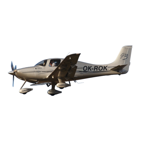
Cirrus SR22 Maintenance Manual
Hide thumbs
Also See for SR22:
- Pilot's operating handbook and flight manual (524 pages) ,
- Pilot operating handbook (502 pages) ,
- Pilot's information manual (204 pages)
Advertisement
Quick Links
C I R R U S
A I R P L A N E M A I N T E N A N C E M A N U A L
1. GENERAL
This chapter contains information on DC Generation, External Power, and Electrical Load Distribution.
The airplane is equipped with a two-alternator, two-battery, 28-volt direct current (VDC) electrical system
designed to reduce the risk of electrical system faults. The system provides uninterrupted power for avion-
ics, flight instrumentation, lighting, and other electrically operated and controlled systems during normal
operation. The electrical system also provides automatic switching from either battery or alternator to the
essential bus in the event of an electrical system failure by the opposing alternator or battery.
Two alternators and two batteries are used to ensure sufficient electrical power. Electrical power is sup-
plied to the essential bus from both batteries and both alternators.
Serials 0002 thru 1839, 1841 thru 1862, 1863 & subs w/o Air Conditioning: Alternator 1 (ALT 1) is a gear-
driven, internally rectified, 60-amp alternator mounted on the right front of the engine.
Serials 1840, 1863 & subs w/ Air Conditioning: Alternator 1 (ALT 1) is a gear-driven, internally rectified,
100-amp alternator mounted on the right front of the engine.
Alternator 2 (ALT 2) is a 20-amp engine-driven alternator mounted to the aft engine accessory pad. ALT 1
is regulated to 28 volts and ALT 2 is regulated to 28.75 volts. Both alternators are self-exciting (not self-
starting) and require battery voltage for field excitation in order to start up
Battery 1 (BAT 1) is an aviation grade 12-cell, lead-acid, 24-volt, 10-amp-hour battery mounted on the right
firewall. BAT 1 is charged from the Main Distribution Bus in the MCU. Battery 2 (BAT 2) is composed of two
12-volt, 7-amp-hour, sealed, lead-acid batteries connected in series to provide 24 volts. BAT 2 is charged
from the circuit breaker panel Essential Bus.
The bolster panel contains the pilot switches for operating ALT 1, ALT 2, BAT 1, and BAT 2. The switches
are mounted adjoining so that a pilot can control all four switches with a single hand.
Power generated from the alternators is fed into the Master Control Unit (MCU). The MCU regulates and
distributes the power to the batteries and the system loads. Each alternator provides constant charging
current for the corresponding battery and primary power to the aircraft electrical system during normal sys-
tem operation.
(See Figure 24-301)
EFFECTIVITY:
All
ELECTRICAL POWER
M O D E L S R 2 2
24-00
Page 1
15 Apr 2007
Advertisement

Subscribe to Our Youtube Channel
Summary of Contents for Cirrus SR22
- Page 1 C I R R U S A I R P L A N E M A I N T E N A N C E M A N U A L M O D E L S R 2 2 ELECTRICAL POWER 1.
-
Page 2: Troubleshooting
C I R R U S A I R P L A N E M A I N T E N A N C E M A N U A L M O D E L S R 2 2 2. - Page 3 C I R R U S A I R P L A N E M A I N T E N A N C E M A N U A L M O D E L S R 2 2 Trouble Probable Cause Remedy...
- Page 4 C I R R U S A I R P L A N E M A I N T E N A N C E M A N U A L M O D E L S R 2 2 Trouble Probable Cause Remedy...
- Page 5 C I R R U S A I R P L A N E M A I N T E N A N C E M A N U A L M O D E L S R 2 2 Trouble Probable Cause Remedy...
- Page 6 C I R R U S A I R P L A N E M A I N T E N A N C E M A N U A L M O D E L S R 2 2 Trouble Probable Cause Remedy...
- Page 7 C I R R U S A I R P L A N E M A I N T E N A N C E M A N U A L M O D E L S R 2 2 Trouble Probable Cause Remedy...
- Page 8 C I R R U S A I R P L A N E M A I N T E N A N C E M A N U A L M O D E L S R 2 2 Trouble Probable Cause Remedy...
- Page 9 C I R R U S A I R P L A N E M A I N T E N A N C E M A N U A L M O D E L S R 2 2 Trouble Probable Cause Remedy...
- Page 10 C I R R U S A I R P L A N E M A I N T E N A N C E M A N U A L M O D E L S R 2 2 Trouble Probable Cause Remedy...


Need help?
Do you have a question about the SR22 and is the answer not in the manual?
Questions and answers