Advertisement
WARNING: This appliance is equipped for
propane gas. Field conversion is not permitted.
WARNING: IF THE INFORMATION IN THIS MANUAL IS NOT FOLLOWED
EXACTLY, A FIRE OR EXPLOSION MAY RESULT CAUSING PROPERTY
DAMAGE, PERSONAL INJURY OR LOSS OF LIFE.
- Do not store or use gasoline or other flammable vapors and Iiquids in vicinity of this or any other appliance.
- An LP cylinder not connected for use shall not be stored in the vicinity of this or any other appliance.
WHAT TO DO IF YOU SMELL GAS
• Extinguish any open flame.
• Shut off gas to appliance.
• Do not try to light any appliance.
• Do not touch any electrical switch; do not use any phone in your building.
• Immediately call your gas supplier from a neighbor's phone. Follow the gas supplier's instructions.
• If you cannot reach your gas supplier, call the fire department.
-Installation and service must be performed by a qualified installer, service agency or the gas supplier.
WARNING: IF THE INFORMATION IN THIS MANUAL IS NOT FOLLOWED
EXACTLY, A FIRE OR EXPLOSION MAY RESULT CAUSING INJURY OR
LOSS OF LIFE.
This is an unvented gas-fired heater. It uses air (oxygen) from the room in which it is
installed. Provisions for adequate combustion and ventilation air must be provided.
Refer to Air For Combustion and Ventilation section on page 7 of this manual.
This appliance may be installed in an aftermarket, permanently located, manufactured (mobile)
home, where not prohibited by local codes.
This appliance is only for use with the type of gas indicated on the rating plate.
This appliance is not convertible for use with other gases.
Questions, problems, missing parts? Before returning to your retailer, call our customer
service department at 1-877-447-4768, 8:30 a.m. – 4:30 p.m., CST, Monday – Friday or
email us at customerservice@ghpgroupinc.com.
INSTALLER: Leave this manual with the appliance.
CONSUMER: Retain this manual for future reference.
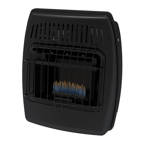
VENT-FREE BLUE FLAME
GAS ICE HOUSE HEATER
Volume II - Unvented Room Heaters
Recreational and Commercial Use.
1
MODEL #
IBF10PMDG
IBF10PTDG
C
US
C
US
ANS Z21.11.2-2013
Gas Fired Room Heaters
CSA IR 4.98 U.S.
Gas Fired Room Heaters For
IMIBF - 2015-08-14
Advertisement
Table of Contents

Related Manuals for Dyna-Glo IBF10PMDG


Summary of Contents for Dyna-Glo IBF10PMDG
- Page 1 VENT-FREE BLUE FLAME GAS ICE HOUSE HEATER MODEL # IBF10PMDG IBF10PTDG ANS Z21.11.2-2013 Gas Fired Room Heaters Volume II - Unvented Room Heaters WARNING: This appliance is equipped for CSA IR 4.98 U.S. propane gas. Field conversion is not permitted.
-
Page 3: Table Of Contents
WARNING: Read the Installation & Operating Instructions before using this appliance. IMPORTANT: Read all instructions and warnings carefully before starting installation. Failure to follow these instructions may result in possible injury to persons or a fire hazard and will void the warranty. PRODUCT SPECIFICATIONS IBF10PMDG SERIES IBF10PTDG MAX BTU 10,000... -
Page 4: Important Safety Information
IMPORTANT SAFETY INFORMATION IMPORTANT: Read this owner’s manual carefully and completely before trying to assemble, operate, or service this heater. Improper use of this heater can cause serious injury or death from burns, fire, explosion, electrical shock, and carbon monoxide poisoning. Installation and repair should be done by a qualified service person. - Page 5 SAFETY INFORMATION WARNING: Do not use any accessories not approved for use with this heater. CALIFORNIA PROPOSITION 65 Fuels used in gas or oil fired appliances and the products of combustion of such fuels contain chemicals known to the state of California to cause cancer, birth defects or other reproductive harm.
-
Page 6: Product Features
PRODUCT FEATURES SAFETY PILOT This heater has a pilot with an Oxygen Depletion Sensing (ODS) safety shutoff system. The ODS/pilot shuts off the heater if there is not enough fresh air and cuts off main burner gas in the event of flame out. ELECTRONIC PUSH BUTTON IGNITION SYSTEM This heater is equipped with an electronic push button ignition system. - Page 7 PREPARING FOR INSTALLATION Before beginning assembly or operation of the product, make sure all parts are present. Compare parts with package contents list. If any part is missing or damaged, do not attempt to assemble, install or operate the product. Contact customer service for replacement parts. UNPACKING 1.
-
Page 8: Air For Combustion And Ventilation
PREPARING FOR INSTALLATION AIR FOR COMBUSTION AND VENTILATION CAUTION: This heater shall not be installed in a room or space unless the required volume of indoor combustion air is provided by the method described in the National Fuel Gas Code, ANSI Z223.1/NFPA54, the International Fuel Gas Code, or applicable local codes. - Page 9 PREPARING FOR INSTALLATION DETERMINING FRESH-AIR FLOW FOR HEATER LOCATION Determining if You Have a Confined or Unconfined Space Use this worksheet to determine if you have a confined or unconfined space. Space: Includes the room in which you will install heater plus any adjoining rooms with doorless passageways or ventilation grills between the rooms.
- Page 10 PREPARING FOR INSTALLATION WARNING: If the recreational or commercial enclosure does not have a window or roof vent, DO NOT USE THIS HEATER inside." Ventilation Air From Inside Building. Note: This heater can only be used in a recreational or commercial enclosure with a window or roof vent.
-
Page 11: Installation
INSTALLATION NOTICE: This heater is intended for use as supplemental heat. Use this heater along with your primary heating system. Do not install this heater as your primary heat source. WARNING: A qualified technician must install heater. Follow all local codes. WARNING: Maintain the minimum clearances. - Page 12 INSTALLATION INSTALLING IGNITOR BATTERY • Battery is included. • Unscrew ignitor cap and insert included battery negative (flat) side down (See Fig. 7). Replace Ignitor cap. • Be sure to observe proper polarity (+/-) when installing or re- Fig. 7 - Installing Ignitor Battery placing the battery.
- Page 13 INSTALLATION Fig. 12- Fan Wiring Diagram Fig. 11 - Operating Fan Caution: Label all wires prior to disconnection when servicing controls. Wiring errors can cause improper and dangerous operation. Fan Rocker If any of the original wire as supplied Switch with the appliance must be replaced, it must be replaced with a wire of at least a 60°C temperature rating.
- Page 14 Clearances (inches) 2. Mark screw locations on wall (See Fig. 13). Note: Mark only last hole on each end of Series IBF10PMDG-1 mounting bracket. Insert (2) wood screws (ST.8*45-16) total through these holes only. IBF10PTDG-1 3. Remove tape and mounting bracket from wall.
- Page 15 INSTALLATION Attaching to Expansion Bracket Method Fig. 14 - Folding the For attaching mounting bracket to hollow walls (wall areas Expansion Bracket between studs) or solid walls (concrete or masonry): 1. Drill holes at marked locations using 5/16-inch drill bit. For solid walls (concrete or masonry), drill at least 1 inch deep.
- Page 16 INSTALLATION CONNECTING TO GAS SUPPLY USING RIGID PIPE WARNING: A qualified service technician must connect heater to gas supply. Follow all local codes. WARNING: Do not overtighten gas connections. CAUTION: Check your gas line pressure before connecting heater to gas line. Gas line pressure must be a minimum 11"...
- Page 17 INSTALLATION CONNECTING TO GAS SUPPLY USING GAS HOSE ASSEMBLY WARNING: A qualified service technician must connect heater to gas supply. Follow all local codes. CAUTION: Avoid damage to regulator. Hold gas regulator with wrench when connecting into gas piping and/or fittings. CAUTION: Use pipe joint sealant that is resistant to gas (Propane or Natural Gas).
- Page 18 INSTALLATION CONNECTING GAS CYLINDER The propane gas supply cylinder to be used must be constructed and marked in accordance with the Specifications for LP Gas Cylinders of the U.S. Department of Transportation (D.O.T.) or the National Standard of Canada, CAN/CSA-B339, Cylinders, Spheres and Tubes for Transportation of Dangerous Goods;...
- Page 19 INSTALLATION WARNING: A qualified service technician must connect heater to gas supply. Follow all local codes. CAUTION: Avoid damage to regulator. Hold gas regulator with wrench when connecting into gas piping and/or fittings. CAUTION: Use pipe joint sealant that is resistant to gas (Propane or Natural Gas). WARNING: Do not overtighten gas connections.
- Page 20 INSTALLATION CHECKING FOR LEAKS After all connections are made, check all connections and fittings on the LP gas tank valve, gas hose and regulator for leaks with a water and soap solution. To prevent fire or explosion while testing for a leak: •...
-
Page 21: Operation
OPERATION FOR YOUR SAFETY READ BEFORE LIGHTING WARNING: If you do not follow these instructions exactly, a fire or explosion may result causing property damage, personal injury or loss of life. A. This appliance has a pilot which must be lighted using the Ignitor. When lighting the pilot, follow these instructions exactly. - Page 22 OPERATION LIGHTING INSTRUCTIONS If the control knob does not pop up when released, stop and immediately and call your service technician or gas supplier. 8. Turn on all electric power to the appliance. 9. Turn control knob counter clockwise to the desired setting. THERMOSTAT GAS CONTROL 1.
- Page 23 OPERATION THERMOSTATIC CONTROL OPERATION (SELECT MODELS) Thermostatic Manual The thermostat used on this heater senses the room tempera- ture. At times the room may exceed the set temperature. If so, the burner will shut off. The burner will cycle back on when room temperature drops below the set temperature.
- Page 24 OPERATION BURNER FLAME PATTERN Fig. 28 shows a correct burner flame pattern. Fig. 29 shows an incorrect burner flame pattern with lifting, and excessive flame height. If burner flame is incorrect: • turn heater off (see “To Turn Off Gas to Appliance”, page 21). •...
-
Page 25: Care And Maintenance
CARE AND MAINTENANCE Fig. 30 - Front Panel Removal NOTE: Before servicing you will need to remove the front panel of the heater. There are 4 Philips head screws, 2 on the left side and 2 on the right, securing the front panel to the heater (See Fig. -
Page 26: Troubleshooting
TROUBLESHOOTING WARNING: If you smell gas: • Shut off gas supply. • Do not try to light any appliance. • Do not touch any electrical switch; do not use any phone in your building. • Immediately call your gas supplier from a neighbor’s phone. Follow the gas supplier’s instructions. •... - Page 27 TROUBLESHOOTING PROBLEM POSSIBLE CAUSE CORRECTIVE ACTION 1. Control knob is not fully ODS/pilot lights 1. Press in control knob fully. pressed in. but flame goes out 2. Control knob is not pressed 2. After ODS/pilot lights, keep control when control knob is in long enough.
- Page 28 TROUBLESHOOTING PROBLEM POSSIBLE CAUSE CORRECTIVE ACTION White powder resi- 1. When heated, the vapors 1. Turn heater off when using furniture due forming within from furniture polish, wax, polish, wax, carpet cleaner or similar burner box or on carpet cleaners, etc., turn products.
- Page 29 TROUBLESHOOTING PROBLEM POSSIBLE CAUSE CORRECTIVE ACTION 1. There is no power to the fan. 1. Verify fan is plugged in and Fan is not spinning. set to "MAN" or "AUTO". (Select Models) 2. Fan is set to "AUTO". 2. Allow 5-10 minutes for fan to engage.
-
Page 30: Replacement Parts
WARNING: Only use genuine replacement parts from the GHP Group, Inc. Using any parts other than the original replacement parts may result in property damage, personal injury or even death. PART NO. ITEM DESCRIPTION IBF10PMDG IBF10PTDG AQ000090A-1 Front Panel Burner Assembly... -
Page 32: Warranty
WARRANTY 1. not be covered by this warranty, nor shall the LIMITED WARRANTY: The manufacturer warrants that your new product is free This limited warranty is extended to the original retail purchaser of this Forced Air/Convection/Radiant Heater and warrants against any manufacturer assume responsibility for same. -
Page 33: Warranty Registration
WARRANTY REGISTRATION IMPORTANT: We urge you to fill out your warranty registration card within fourteen (14) days of date of purchase. You can also register your warranty on the internet at www.ghpgroupinc.com. Complete the entire serial number. Retain this portion of the card for your records.