Dyna-Glo IR12DTL-2 Manual

Dyna-Glo IR12DTL-2 Manual

Vent-free infrared gas wall heater

Advertisement

WARNING: This appliance is equipped for
Natural and Propane gas. Field conversion is
not permitted.
WARNING: Do not attempt to access or change
the setting of the fuel selection means.
Access to and adjustment of the fuel selection means
must only be performed by a qualified service person
when connecting this appliance to a specified fuel
supply at the time of installation.
Change of the selector setting to other than the fuel type
specified at the time of installation could damage this
appliance and render it inoperable.
The installer shall replace the access cover before
completing the installation and operating this appliance.
WARNING: IF THE INFORMATION IN THIS MANUAL IS NOT FOLLOWED
EXACTLY, A FIRE OR EXPLOSION MAY RESULT CAUSING PROPERTY
DAMAGE, PERSONAL INJURY OR LOSS OF LIFE.
- Do not store or use gasoline or other flammable vapors and Iiquids in vicinity of this or
any other appliance.
WHAT TO DO IF YOU SMELL GAS
• Do not try to light any appliance.
• Do not touch any electrical switch; do not use any phone in your building.
• Immediately call your gas supplier from a neighbor's phone. Follow the gas supplier's
instructions.
• If you cannot reach your gas supplier, call the fire department.
- Installation and service must be performed by a qualified installer, service agency or the
gas supplier.
This is an unvented gas-fired heater. It uses air (oxygen) from the room in which it is
installed. Provisions for adequate combustion and ventilation air must be provided.
Refer to Air For Combustion and Ventilation section on page 7-9 of this manual.
This appliance may be installed in an aftermarket, permanently located, manufactured (mobile)
home, where not prohibited by local codes.
This appliance is only for use with propane or natural gas.
This appliance is equipped with a simple means to switch between propane and natural gas.
Field conversion by any other means including the use of a kit is not permitted.
Questions, problems, missing parts? Before returning to your retailer, call our customer
service department at 1-877-447-4768, 8:30 a.m. – 4:30 p.m., CST, Monday – Friday or
email us at customerservice@ghpgroupinc.com.
INSTALLER: Leave this manual with the appliance.
CONSUMER: Retain this manual for future reference.
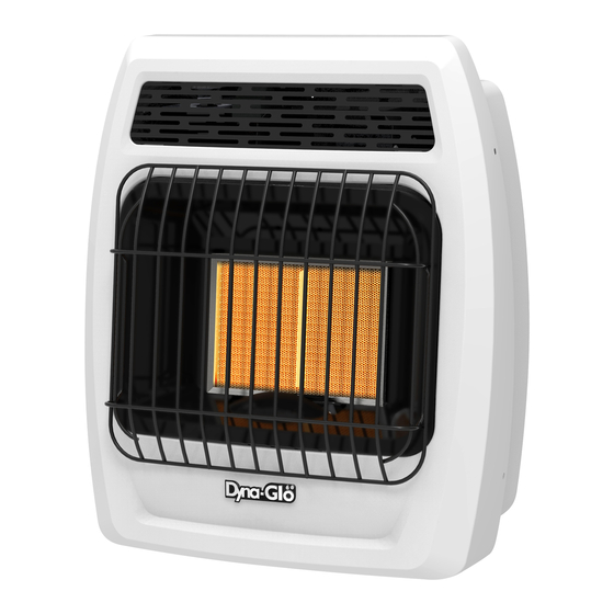
VENT-FREE INFRARED
Volume II - Unvented Room Heaters
1
GAS WALL HEATER
MODEL # IR12DTL-2
IR18DTL-2
IR30DTL-2
Patent Pending Dual
Fuel System
C
US
C
US
ANS Z21.11.2-2016
Gas Fired Room Heaters
IMDFIRG2L - 2018-09-06

Advertisement

Table of Contents
loading

Summary of Contents for Dyna-Glo IR12DTL-2

  • Page 1 VENT-FREE INFRARED GAS WALL HEATER MODEL # IR12DTL-2 IR18DTL-2 IR30DTL-2 WARNING: This appliance is equipped for Natural and Propane gas. Field conversion is not permitted. Patent Pending Dual Fuel System WARNING: Do not attempt to access or change the setting of the fuel selection means.
  • Page 3: Table Of Contents

    IMPORTANT: Read all instructions and warnings carefully before starting installation. Failure to follow these instructions may result in possible injury to persons or a fire hazard and will void the warranty. PRODUCT SPECIFICATIONS SERIES IR12DTL-2 MAX BTU 12,000 12,000 Fuel Type...
  • Page 4: Important Safety Information

    IMPORTANT SAFETY INFORMATION WARNING: FIRE, EXPLOSION, AND ASPHYXIATION HAZARD Improper adjustment, alteration, service, maintenance, or installation of this heater or its controls can cause death or serious injury. Read and follow instructions and precautions in User's Information Manual provided with this heater. IMPORTANT: Read this owner’s manual carefully and completely before trying to assemble, operate, or service this heater.
  • Page 5 SAFETY INFORMATION WARNING: If the heater is being installed in a residential garage, it must be secured firmly to the wall, a minimum of 18 in. (457mm) above the floor. The heater must be located so that it is protected against any possibility of damage by a moving vehicle, etc. Raising the heater will reduce BUT NOT eliminate the possibility of lighting the vapor of any flammable liquids which may be improperly stored or accidentally spilled.
  • Page 6: Product Features

    PRODUCT FEATURES SAFETY PILOT This heater has a pilot with an Oxygen Depletion Sensing (ODS) safety shutoff system. The ODS/pilot shuts off the heater if there is not enough fresh air and cuts off main burner gas in the event of flame out. DUAL FUEL CAPABILITY Your heater is equipped to operate on either propane or natural gas.
  • Page 7 PREPARING FOR INSTALLATION Before beginning assembly or operation of the product, make sure all parts are present. Compare parts with package contents list. If any part is missing or damaged, do not attempt to assemble, install or operate the product. Contact customer service for replacement parts. UNPACKING 1.
  • Page 8: Air For Combustion And Ventilation

    PREPARING FOR INSTALLATION AIR FOR COMBUSTION AND VENTILATION CAUTION: This heater shall not be installed in a room or space unless the required volume of indoor combustion air is provided by the method described in the National Fuel Gas Code, ANSI Z223.1/NFPA54, the International Fuel Gas Code, or applicable local codes.
  • Page 9 PREPARING FOR INSTALLATION DETERMINING FRESH-AIR FLOW FOR HEATER LOCATION Determining if You Have a Confined or Unconfined Space Use this worksheet to determine if you have a confined or unconfined space. Space: Includes the room in which you will install heater plus any adjoining rooms with doorless passageways or ventilation grills between the rooms.
  • Page 10 PREPARING FOR INSTALLATION Ventilation Air From Inside Building Ventilation Air from Inside Building This fresh air would come from adjoining unconfined space. When ventilating to an 12 in. adjoining unconfined space, you must provide two permanent openings: one within 12 in. of the wall connecting Ventilation Grills the two spaces (see options 1 and 2, Into Adjoining Room,...
  • Page 11: Installation

    INSTALLATION NOTICE: This heater is intended for use as supplemental heat. Use this heater along with your primary heating system. Do not install this heater as your primary heat source. WARNING: A qualified technician must install heater. Follow all local codes. WARNING: Maintain the minimum clearances.
  • Page 12: Gas Conversion

    INSTALLATION GAS SELECTION CAUTION: The knob to the gas selection means shall not be accessed or adjusted while the appliance is in operation. WARNING: Gas selection should only be done by a qualified technician. WARNING: The unused regulator must be fitted with a metal plug with a pipe thread sealant. WARNING: Failure to plug the unused regulator may result in a fire, property damage, personal injury, or death.
  • Page 13 INSTALLATION INSTALLATION Fig. 6 - Checking Manifold GAS SELECTION Pressure IMPORTANT: Before proceeding with the installation, the qualified ser- INLET vice technician converting the heater between gas supplies must verify correct manifold pressure. A reading can be taken using a pressure gauge and the appropriate pressure tap (See Fig.
  • Page 14 INSTALLATION Fig. 12- Fan Wiring Diagram Fig. 11 - Operating Fan Fan Switch AUTO Fan Rocker Thermo-switch 110/115 Switch Black White Green LOCATING HEATER Wiring Diagram This heater is designed to be mounted on a wall or on Fig. 13 - Attaching Legs a floor, using the Support Legs (Select Models) includ- ed with select models.
  • Page 15 Make sure mounting bracket Clearances (inches) is level. 2. Mark screw locations on wall (See Fig. 16). Series IR12DTL-2 Note: Mark only last hole on each end of mounting bracket. Insert (2) wood screws (ST.8*45-16) total through these holes only.
  • Page 16 INSTALLATION Attaching to Expansion Bracket Method Fig. 17 - Folding the For attaching mounting bracket to hollow walls (wall areas Expansion Bracket between studs) or solid walls (concrete or masonry): 1. Drill holes at marked locations using 5/16-inch drill bit. For solid walls (concrete or masonry), drill at least 1 inch deep.
  • Page 17 INSTALLATION CONNECTING TO GAS SUPPLY WARNING: A qualified service technician must connect heater to gas supply. Follow all local codes. IMPORTANT: This appliance requires a 3/8-inch NPT (National Pipe Thread) inlet connection to the pressure regulator. Never connect the heater to private (non-utility) gas wells, commonly known as wellhead gas.
  • Page 18 INSTALLATION Fig. 20 - Gas Connection Install sediment trap in supply line as shown (See Fig. 20). Place sediment trap where it is within reach for cleaning. Place sediment trap where trapped matter is not likely to freeze. A sediment trap traps moisture and contaminants. This keeps them from going into heater controls.
  • Page 19: Operation

    OPERATION FOR YOUR SAFETY READ BEFORE LIGHTING WARNING: If you do not follow these instructions exactly, a fire or explosion may result causing property damage, personal injury or loss of life. A. This appliance has a pilot which must be lighted using the Ignitor. When lighting the pilot, follow these instructions exactly.
  • Page 20 OPERATION LIGHTING INSTRUCTIONS If the control knob does not pop up when released, stop and immediately and call your service technician or gas supplier. 8. Turn on all electric power to the appliance. 9. Turn control knob counter clockwise to HIGH " "...
  • Page 21 OPERATION OPERATION OPERATION LIGHTING INSTRUCTIONS Burner Patterns (Thermostatic Control) TO TURN OFF GAS TO APPLIANCE 1. Turn off all electric power to the appliance if service is to be performed. 2. Push in gas control knob slightly and turn clockwise to "OFF"...
  • Page 22 OPERATION INSPECTING BURNERS Check pilot flame pattern daily when in use and at least yearly by a qualified service agency. PILOT FLAME PATTERN Fig. 26 shows a correct pilot flame pattern. Fig. 27 shows an incorrect pilot flame pattern. The incor- rect pilot flame is not touching the thermocouple.
  • Page 23: Care And Maintenance

    CARE AND MAINTENANCE Front Panel Removal NOTE: Before servicing you will need to remove the front panel of the Fig. 30 - Front Panel Removal heater. There are 4 Philips head screws, 2 on the left side and 2 on the right, securing the front panel to the heater (See Fig.
  • Page 24: Troubleshooting

    TROUBLESHOOTING WARNING: If you smell gas: • Shut off gas supply. • Do not try to light any appliance. • Do not touch any electrical switch; do not use any phone in your building. • Immediately call your gas supplier from a neighbor’s phone. Follow the gas supplier’s instructions. •...
  • Page 25 TROUBLESHOOTING PROBLEM POSSIBLE CAUSE CORRECTIVE ACTION 1. Control knob is not fully ODS/pilot lights 1. Press in control knob fully. pressed in. but flame goes out 2. Control knob is not pressed 2. After ODS/pilot lights, keep control when control knob is in long enough.
  • Page 26 TROUBLESHOOTING PROBLEM POSSIBLE CAUSE CORRECTIVE ACTION White powder 1. When heated, the vapors 1. Turn heater off when using furniture residue forming from furniture polish, wax, polish, wax, carpet cleaner or similar within burner box or carpet cleaners, etc., turn products.
  • Page 27 TROUBLESHOOTING PROBLEM POSSIBLE CAUSE CORRECTIVE ACTION Fan is not spinning. 1. There is no power to the fan. 1. Verify fan is plugged in and set to (Select models) "MAN" or "AUTO". 2. Fan is set to "AUTO". 2. Allow 5-10 minutes for fan to engage. 3.
  • Page 28: Replacement Parts

    REPLACEMENT PARTS LIST For replacement parts, call our customer service department at 1-877-447-4768, 8:30 a.m. – 4:30 p.m., CST, Monday – Friday. WARNING: Only use genuine replacement parts from the GHP Group, Inc. Using any parts other than the original replacement parts may result in property damage, personal injury or even death. 10-1 10-2 Part Number...
  • Page 29: Warranty

    WARRANTY 1. not be covered by this warranty, nor shall the LIMITED WARRANTY: The manufacturer warrants that your new product is free This limited warranty is extended to the original retail purchaser of this Forced Air/Convection/Radiant Heater and warrants against any manufacturer assume responsibility for same.
  • Page 30 WARRANTY REGISTRATION IMPORTANT: We urge you to fill out your warranty registration card within fourteen (14) days of date of purchase. You can also register your warranty on the internet at www.ghpgroupinc.com. Complete the entire serial number. Retain this portion of the card for your records.

This manual is also suitable for:

Ir18dtl-2Ir30dtl-2

Table of Contents