Advertisement
Table of Contents
- 1 Table of Contents
- 2 Safety Informations
- 3 Technical Features
- 4 Before Using
- 5 Lamp Installation, Replacement and Setting
- 6 Installation of the Dust Proof Filters
- 7 Control Panel and Configuration
- 8 Programming Functions
- 9 DMX Signal Connection
- 10 DMX Line and Termination
- 11 Use of the Citycolor in DMX 512
- 12 Automode Functioning
- 13 Troubleshooting
- 14 System Board Connection
- Download this manual
Safety informations ........................................................................................................................... page 2
Technical features.............................................................................................................................. page 3
Before using....................................................................................................................................... page 4
Lamp installation, replacement and setting .................................................................................... page 5
Installation of the dust proof filters .................................................................................................. page 6
Control panel and configuration ...................................................................................................... page 7
Programming functions .................................................................................................................... page 8
Use of the CityColor in DMX 512 ..................................................................................................... page 9
DMX signal connection..................................................................................................................... page 10
DMX line and termination ................................................................................................................ page 11
Automode functioning ...................................................................................................................... page 12
Troubleshooting ............................................................................................................................... page 13
System board connection ................................................................................................................ page 15
Electric diagrams
.......................................................................................................................... page 17
Components and parts...................................................................................................................... page 22
Technical drawings............................................................................................................................ page 23
Appendix A (DMX values) ................................................................................................................ page 26
Appendix B (games).......................................................................................................................... page 27
rev. 4/02.05
petri konferenztechnik.de
Full Service in Konferenz-, Messe- und Veranstaltungstechnik
Petri Konferenztechnik GmbH
Zentrale
Crailsheimer Str. 1, 90574 Roßtal/Buchschwabach
Telefon
+49 (0) 91 27 - 90 33 80
Telefax
+49 (0) 91 27 - 90 33 89
e-Mail
info@petri-konferenztechnik.de
INTERNATIONAL PATENT WO99/40361
Zweigstelle
Lerchenbühlstr. 17, 90419 Nürnberg
Telefon
+49 (0) 911 - 80 13 220
Telefax
+49 (0) 911 - 80 13 221
www.petri-konferenztechnik.de
Advertisement
Table of Contents

Related Manuals for STUDIO DUE CITYCOLOR 2500 IP54


Summary of Contents for STUDIO DUE CITYCOLOR 2500 IP54
-
Page 1: Table Of Contents
Safety informations ........................... page 2 Technical features..........................page 3 Before using............................page 4 Lamp installation, replacement and setting ..................page 5 Installation of the dust proof filters ....................page 6 Control panel and configuration ...................... page 7 Programming functions ........................page 8 Use of the CityColor in DMX 512 ..................... -
Page 2: Safety Informations
WARNING SAFETY INFORMATION READ ALL CAUTIONS AND WARNINGS PRIOR TO OPERATE THIS EQUIPMENT. INSTRUCTION TO PREVENT INJURY OR DAMAGE DUE TO ELECTRIC SHOCK, FIRE, MECHANICAL HAZARDS AND UV RADIATION HAZARDS. • PROTECTION AGAINTS FIRE 1) IMPORTANT: Use only the lamps showed on page n. 3. DO NOT USE ANY OTHER TYPE LAMP! 2) Maintain minimum distance of 0.5 meter from walls or any other type flammable surfaces. -
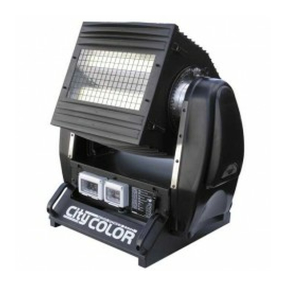
Page 3: Technical Features
The basic kit of the CityColor flood projector consist of: •Projector •User’s manual •Power connector •Studio Due warranty Available on request: •art. 9801/a: barndoor to define illuminated surface •art. 0003/a: anti glare •art. 0002/a: XLR 3 pin male IP54 connectors •art. -
Page 4: Before Using
CIRCUIT BREAKER MAINS VOLTAGE 230V 0,03A INPUT CONNECTOR FOR 1800W Ke ep ® at lea st a Dis co dis tan C IT C IT nn ec an d ce of 23 0 23 0 t the inf lam un it ma ble 0.5 mt M ar... -
Page 5: Lamp Installation, Replacement And Setting
pict.2 In case of replacement of the lamp or maintenance, do not open the fixture unless 5 minutes have passed from the switching off. WARNING This operation has to be done when the apparatus is disconnected from the mains supply INSTALLATION OF THE DISCHARGE LAMP (art. -
Page 6: Installation Of The Dust Proof Filters
IP RATE The declared IP rate of the CityColor comes supported at these conditions: • the installation of the fixture on a wide and stable surface • the air cooling input and output are located on the base of the side-shell, it is not possible to install the fixture outdoor with the ballast upwards •... -
Page 7: Control Panel And Configuration
pict.4 CONTROL PANEL On the control panel of the CityColor (pict.4) you can find, besides the display, the leds and the buttons to use to set the spot. • “DMX” led flashing: DMX input present off: no DMX input • ”LAMP” led flashing: the lamp switching off is remotely controlled off:... -
Page 8: Programming Functions
SUMMARY OF THE PROGRAMMING FUNCTIONS OF THE CITYCOLOR Addr nChn teSt Mode LHrS FLIP rSEt FHrS About twenty seconds after the switching on, the number of the software version will be shown on the display in “X_00” format. Afterwards the first of the eight available menus will appear: Addr to assign the DMX-512 address Mode DMX512 mode, master with pre-set selection, slave... - Page 9 nChn (Number of Channel) To visualise the number of channel press ENTER. Use Down and Up buttons to change the channel and, once the required one has been selected, press and keep ENTER pressed up to when the display stops flashing (it flashes to indicate that the selected option is different from the pre-set one). It is possible to set 6 channels or 7 channels ( remote reset and remote lamp switch off ).
-
Page 10: Dmx Signal Connection
CONNECTION THE DATA LINK (DMX 512) WIRE SIGNAL SHIELD GROUND/RETURN/OV INNER CONDUCTOR DATA COMPLEMENT (-, INVERTED) INNER CONDUCTOR DATA TRUE (+, NON INVERTED) pict.5a pict.5 fig.5c fig.5b The connection of the DMX signal to the CITYCOLOR must be made by using the signal input XLR 5 pin connectors which are located on the control panel of the fixture. -
Page 11: Dmx Line And Termination
WARNING DMX TERMINAL LINE The wrong connection of the terminal line or its non-connection are probably the most frequent reasons for the defective functioning of the DMX line. The terminator is a resistor fitted between the two “data” lines (pins 2 and 3 of an XLR 5 pin connector) at the end of the cable furthest from the transmitter. -
Page 12: Use Of The Citycolor In Dmx 512
MASTER pict.7 USE OF THE CITYCOLOR IN AUTO-MODE A short list of the games can be found in appendix “B”, page 27 Press the MENU button on the control panel up to when the option MODE (pict. 7) is shown on the display, select it by press ing EN TER and the set indication will appear (no...SL). -
Page 13: Troubleshooting
• Description of the problem and the troubleshooting procedures that you have performed so far to diagnose and resolve the fault. You can contact your authorized STUDIO DUE dealer or directly STUDIO DUE Technical Service. (tel. +39.0761.352520 or fax +39.0761.352653 - e-mail: service@studiodue.com or customer@studiodue.com) GENERAL TOUBLESHOOTING Appendix “C”... - Page 14 DATA LINK (512 DMX) TOUBLESHOOTING Appendix “C” • Table A2...
-
Page 15: System Board Connection
MAIN BOARD CONNECTION U5 U6 U7 U8 U9 L6219 MOTOR DRIVER U4 MICRO SLAVE MOTOR U3 MICRO MASTER MOTOR CCSLAVEXX U11 VIPER SWITCHING LED +5V CC3DRVXX POWER SUPPLY DRIVER LED +5V OPTO DMX U13 78M05 OPTO DMX TO DISPLAY PCB PAN IP LED DMX SIGNAL 320V DC... - Page 16 MOTORS BOARD • POWER SUPPLY +30V Led On • +5V Led • +320V Led •+5V DMX Led • DMX signal Led flashing: the DMX signal is operating on the board Led off: check the U1 (6N137) and the DMX connecting cable (from PCB PAN IP) •...
Need help?
Do you have a question about the CITYCOLOR 2500 IP54 and is the answer not in the manual?
Questions and answers