Advertisement
Table of Contents
1
10
20
2
4
5
11
6
7
12
3
13
14
15
16
17
FIG.
PART NO.
DESCRIPTION OF PART
1
05-84-0835
Bolt Assembly
2
42-92-1440
Top Cap
3
42-38-0385
Bumper Band
4
42-76-0820
Valve Collar
5
40-50-3105
Upper Valve Spring
6
44-62-0270
Head Valve Piston
7
45-06-0935
Seal
8
44-90-0815
Piston Ring
9
---------------
Driver Assembly
10
34-40-3210
O-Ring, 23 mm x 2 mm
11
42-76-0810
Valve Collar
12
42-98-0365
Cylinder
13
34-40-3215
O-Ring, 32 mm x 2 mm
14
44-90-0725
Cylinder Ring
15
45-36-1650
Cylinder Spacer
16
34-40-3185
O-Ring, 47.5 mm x 2 mm
17
42-38-0305
Bumper
18
---------------
Driver Guide
19
45-06-0905
Top Cap Seal
20
05-84-0950
Set Screw M4 x 0.7-6
21
45-06-0955
Seal
22
43-64-0145
Trigger Valve Head
23
40-50-3190
Trigger Valve Spring
24
44-70-0260
Trigger Valve Plunger
25
34-40-3290
O-Ring
26
34-40-3160
O-Ring, 2.5 mm x 1.5 mm
27
34-40-3305
O-Ring
28
42-52-0415
Trigger Valve Plunger Cap
29
44-10-0660
Selector
30
40-50-3210
Selection Spring
31
40-50-3155
Spring
32
31-92-0205
Trigger Assembly
33
44-86-0710
Retainer
SERVICE PARTS LIST
SPECIFY CATALOG NO. AND SERIAL NO. WHEN ORDERING PARTS
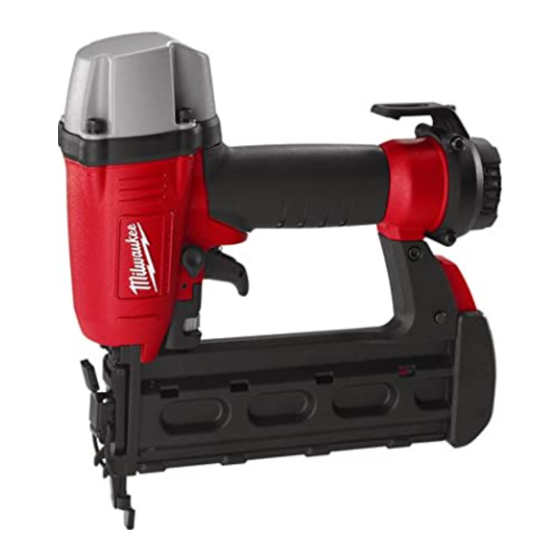
BRAD NAILER
CATALOG NO. 7150-21
94
9 18
37
49
8
9
35
19
33
18
EXAMPLE:
00
0
Component Parts (Small #) Are Included
When Ordering The Assembly (Large #).
NO. REQ.
STARTING
SERIAL NUMBER
38
36
30
34
29
21
22
23
24
21 22 23 24 25
92
25
26 27 28 35
26
28
27
31
FIG.
PART NO.
4
34
06-65-1435
1
35
44-90-0825
1
36
28-50-0820
1
37
34-40-3155
1
38
44-94-0565
1
39
43-31-0380
1
40
43-44-1250
1
41
42-70-0410
1
42
42-92-1370
1
43
43-31-0365
1
44
05-84-0975
1
45
31-05-0415
1
46
40-50-3020
1
47
45-08-0460
1
48
05-83-0535
1
62
44-90-0780
1
76
43-98-0765
1
77
43-56-0885
1
78
43-78-0450
1
79
40-50-3045
1
80
44-90-0760
1
81
42-36-1990
1
82
44-94-0590
1
83
42-36-2025
1
84
05-84-0875
1
85
42-36-1965
1
86
42-38-0340
1
90
02-02-2100
1
94
43-12-0267
1
1
1
1
PAGE 1 OF 2
BULLETIN NO.
REVISED BULLETIN
WIRING INSTRUCTION
A90A
20
48
46
47
41
40
39
43
42
90
74
46
79
32
80
81
82
83
84
85
86
DESCRIPTION OF PART
Spring Pin, 3 mm x 25 mm
Ring
Tool Body
O-Ring
Link Rod
Filter
End Cap Gasket
Spring Retainer (Belt Clip)
End Cap
Muffl er
Bolt, M5 x 0.8-25
Defl ector
Spring
Positioning Shaft
Round Head Philips Bolt
E-Ring
Adjustment Knob
Work Contact Element Guide
Work Contact Element Spring Hub
Work Contact Element Spring
E-Ring
Work Contact Element
Adjustment Rod Assembly
Work Contact Bracket B
Bolt M4 x 0.7-4
Work Contact Element A
No Mar Pad
Ball
Driver Assembly Kit
MILWAUKEE ELECTRIC TOOL CORPORATION
13135 W. Lisbon Road, Brookfi eld, WI 53005
54-43-0060
DATE
Mar. 2008
44
45
44
78
76
77
80
NO. REQ.
1
1
1
2
1
1
1
1
1
1
1
1
1
1
2
1
1
1
1
1
1
1
1
1
1
1
1
1
1
Drwg. 3
Advertisement
Table of Contents

Summary of Contents for Milwaukee 7150-21
- Page 1 SPECIFY CATALOG NO. AND SERIAL NO. WHEN ORDERING PARTS CATALOG NO. 7150-21 FIG. PART NO. DESCRIPTION OF PART 05-84-0835 Bolt Assembly 42-92-1440 Top Cap 42-38-0385 Bumper Band 42-76-0820 Valve Collar 40-50-3105 Upper Valve Spring 44-62-0270 Head Valve Piston 45-06-0935 Seal...
- Page 2 FIG. PART NO. DESCRIPTION OF PART --------------- Driver Guide 05-83-0505 Half Round Hex Bolt (M4 x 0.7-12) 42-92-1405 Cover, Driver Guide B 42-92-1390 Cover, Driver Guide A 44-60-1865 Fixed Pin 45-88-1705 Lock Handle Grip 06-65-1450 Spring Pin 44-20-0855 Lock Handle Assembly 43-40-0465 Magazine A 05-84-0880...
- Page 3 Disassembly: 1, 2 Remove hex bolts (1) from top cap (2) using a 4mm hex key. 2, 4, 5, 6, 7 Remove valve assembly 4, 5, 6, and 7 from top cap (2) using a fl at blade screwdriver. 11, 12 Remove press ring (11) from top of cylinder (12) prior to removing driver/cylinder assemblies.


Need help?
Do you have a question about the 7150-21 and is the answer not in the manual?
Questions and answers