Advertisement
Quick Links
EXAMPLE:
00
Component Parts (Small #) Are Included
0
When Ordering The Assembly (Large #).
2
3
15
4
5
16
1
6
17
18
9
10
11
12
19
20
7
8
13
21
14
22
23
FIG.
PART NO.
DESCRIPTION OF PART
1
05-84-0845
Bolt Assembly
2
05-84-0805
Deflector Bolt
3
31-05-0400
Deflector
4
43-31-0355
Muffler
5
45-88-1720
Deflector Pad
6
42-92-1420
Top Cap
7
45-06-0925
Seal Gasket
8
45-06-0940
Seal
9
40-50-3110
Upper Valve Spring
10
44-62-0250
Head Valve Piston
11
34-40-3240
O-Ring
12
34-40-3175
O-Ring
13
42-76-0800
Valve Collar
14
45-06-0910
Top Cap Seal
15
44-90-0700
Cylinder Press Ring
16
44-90-0820
Piston Ring
17
34-40-3220
O-Ring
18
43-12-0250
Driver Assembly
19
34-40-3270
O-Ring
20
42-98-0350
Cylinder
21
44-90-0800
Cylinder Spacer
22
42-38-0300
Bumper
23
43-56-0895
Driver Guide
24
42-38-0360
Bumper Band
25
34-40-3295
O-Ring
26
34-40-3300
O-Ring
27
42-52-0410
Plunger Cap
28
44-70-0250
Trigger Valve Plunger
29
34-40-3285
O-Ring
30
34-40-3280
O-Ring
31
40-50-3195
Spring
32
44-70-0255
Plunger
33
34-40-3290
O-Ring
34
43-64-0150
Trigger Valve Head
SERVICE PARTS LIST
SPECIFY CATALOG NO. AND SERIAL NO. WHEN ORDERING PARTS
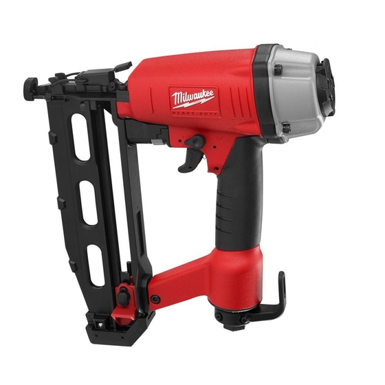
STRAIGHT FINISH NAILER
CATALOG NO. 7145-21
24
42
43
NO. REQ.
STARTING
SERIAL NUMBER
46
45
44
82
37
36
40
41
85
91
86
92
87
93
88
89
94
90
95
FIG.
PART NO.
4
35
06-65-1465
1
36
06-65-1440
1
37
06-65-1480
1
38
31-92-0200
1
39
40-50-3160
1
40
44-10-0650
1
41
40-50-3095
1
42
44-86-0710
1
43
44-90-0825
1
44
28-50-0800
1
45
44-90-0785
1
46
43-31-0370
1
47
34-40-3250
1
48
42-92-1350
1
49
05-84-0950
1
50
40-50-3180
1
51
45-08-0460
1
52
42-70-0400
1
53
05-83-0525
1
85
43-56-0865
1
86
06-65-1405
1
87
40-50-3050
1
88
42-36-2050
1
89
43-98-0755
1
90
42-92-1495
1
91
44-94-0570
1
92
34-40-3310
1
93
42-36-1995
2
94
44-90-0770
1
95
42-38-0320
1
1
2
1
PAGE 1 OF 2
BULLETIN NO.
54-43-0050
REVISED BULLETIN
WIRING INSTRUCTION
A89A
48
47
25
26
27
35
28
29
25 26 27 28 29 30
97
30
31 32 33 34 35 43
31
32
33
34
39
38
DESCRIPTION OF PART
Spring Pin
Spring Pin
Spring Pin
Trigger Assembly
Spring
Selector
Selector Spring
Retainer
Ring
Tool Body
Snap Ring
Filter
O-Ring
End Cap
Socket Head Hex Screw
Positioning Spring
Positioning Shaft
Spring Retainer (Belt Clip)
Round Head Phillips Bolt
Work Contact Element Guide
Spring Pin
Work Contact Spring
Work Contact Assembly B
Adjustment Knob
Work Contact Element Cover
Adjustment Rod
O-Ring
Work Contact Element Bracket A
E-Ring
No-Mar Pad
MILWAUKEE ELECTRIC TOOL CORPORATION
13135 W. Lisbon Road, Brookfield, WI 53005
DATE
Mar. 2006
52
51
50
49
53
NO. REQ.
1
2
1
1
1
1
1
1
1
1
1
1
1
1
1
1
1
1
2
1
1
1
1
1
1
1
1
1
1
1
Drwg.2
Advertisement

Subscribe to Our Youtube Channel
Summary of Contents for Milwaukee 7145-21
- Page 1 SPECIFY CATALOG NO. AND SERIAL NO. WHEN ORDERING PARTS CATALOG NO. 7145-21 EXAMPLE: Component Parts (Small #) Are Included When Ordering The Assembly (Large #). FIG. PART NO. DESCRIPTION OF PART 05-84-0845 Bolt Assembly 05-84-0805 Deflector Bolt 31-05-0400 Deflector 43-31-0355...
- Page 2 FIG. PART NO. DESCRIPTION OF PART 05-84-0995 Bolt Assembly 42-92-1395 Driver Guide Cover B 42-92-1380 Driver Guide Cover A 06-65-1455 Spring Pin 45-88-1705 Pusher Cushion 44-20-0850 Lock Handle Assembly 06-65-1450 Spring Pin 44-60-1855 Fixed Pin 43-56-0855 Driver Guide 44-90-0760 E-Ring 05-83-0515 Half Round Hex Bolt 44-86-0705...
- Page 3 Disassembly: 2, 3, 4, 5, 6 Remove hex bolt (2), deflector (3), muffler (4) and deflector pad (5) from top cap (6). 4 mm hex key required. 1, 6 Remove hex bolts (1) to remove top cap (6). 4 mm hex key required. 7, 8, 9, 10, 11, 12, 13 Remove valve assembly (7, 8, 9, 10, 11, 12, and 13) out of the top cap using a 1/8 in.
- Page 4 Lubrication: Type I Grease 49-08-7100 Clean all parts with a dry clean cloth. 6, 7, 8, 9, 10, 11, 12, 13 Place a thin coating of grease into internal bore of top cap (6), coat parts (7 – 13) and reassemble in order shown. 16, 17, 18 Coat o-ring (17) and piston ring (16) prior to installing into groove of driver assembly (18).


Need help?
Do you have a question about the 7145-21 and is the answer not in the manual?
Questions and answers