Table of Contents
Advertisement
Quick Links
INFRARED WIRELESS TUNER
This manual describes the installation and usage of the entire system* using the IR-702T Infrared
Wireless Tuner as well as the IR-702T.
* The system described in this manual is comprised of the following components:
• IR-702T Infrared Wireless Tuner
• IR-200M and IR-300M Infrared Wireless Microphones
• IR-500R, IR-510R, and IR-520R Infrared Wireless Receivers
• IR-200BC Battery Charger
• IR-200BT-2 Ni-MH Battery
• YW-1022 and YW-1024 Distributors
Note
For the installation and usage of the IR-702T when used in combination with the IR-700D
Infrared Wireless Distributor, refer to the installation manual enclosed with the IR-700D.
Thank you for purchasing TOA's Infrared Wireless Tuner.
Please carefully follow the instructions in this manual to ensure long, trouble-free use of your equipment.
C H
A
V O
I R
L U
M E
C H
B
I R
V O
L U
M E
O N
O F
F
P O
W E
R
OPERATING INSTRUCTIONS
IR-702T
133-07-275-8B
Advertisement
Table of Contents

Related Manuals for Toa IR-702T


Summary of Contents for Toa IR-702T
-
Page 1: Operating Instructions
OPERATING INSTRUCTIONS INFRARED WIRELESS TUNER IR-702T This manual describes the installation and usage of the entire system* using the IR-702T Infrared Wireless Tuner as well as the IR-702T. * The system described in this manual is comprised of the following components: •... -
Page 2: Table Of Contents
TABLE OF CONTENTS 1. SAFETY PRECAUTIONS ...................... 3 2. GENERAL DESCRIPTION ....................4 3. FEATURES ..........................4 4. HANDLING PRECAUTIONS ....................4 5. NOMENCLATURE AND FUNCTIONS Front ............................... 5 Rear ..............................5 6. OPERATIONS ........................... 6 7. SYSTEM CONFIGURATION EXAMPLES 7.1.Using 2 Infrared Wireless Receivers .................. -
Page 3: Safety Precautions
1. SAFETY PRECAUTIONS These precautions apply only to the IR-702T Infrared Wireless Tuner. For precautions regarding other infrared microphone system devices, please refer to the instruction manual included with each device. • Before installation or use, be sure to carefully read all the instructions in this section for correct and safe operation. -
Page 4: General Description
• Up to 16 infrared wireless receivers can be installed with the use of the IR-700D Infrared Wireless Distributor. • Since the IR-702T tuner uses a frequency band that does not interfere with that of the infrared conference system (TS-800 and TS-900 Series), both the infrared wireless microphone system and the conference system can be simultaneously installed in the same location. -
Page 5: Nomenclature And Functions
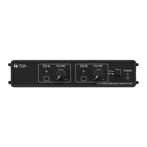
5. NOMENCLATURE AND FUNCTIONS [Front] CH A VOLUME CH B VOLUME POWER Note: Functions of the (3), (4), and (5) for the Channel A also apply to the Channel B (CH-B). [Rear] IR IN OUTPUT –10dBV/600Ω 75 Ω CH B CH A/MIX DC IN CH A... -
Page 6: Operations
6. OPERATIONS Note: The example here shows the operation of the Channel A. This operation also applies to the Channel B. Power switch Volume control knob Power switch Infrared wireless microphone IR-300M CH A VOLUME CH B VOLUME Infrared wireless microphone POWER IR-200M Reception indicator... -
Page 7: System Configuration Examples
7.1. Using 2 Infrared Wireless Receivers Infrared Wireless Receiver IR-500R, IR-510R, or IR-520R Note Connect one each of the IR-510R or IR-520R Infrared Wireless Receivers to the IR-702T's Receiver input terminals 1 and 2. Infrared Wireless Microphone Infrared Wireless Tuner IR-200M IR-702T... -
Page 8: Simultaneous Use Of The Infrared Wireless Microphone System And The Infrared Conference System
IR-500R, IR-510R or IR-520R YW-1022* Infrared Wireless Microphone IR-200M Infrared Wireless Microphone IR-300M Infrared Wireless Tuner IR-702T Note Both systems can be installed in the same location. Infrared Conference System (TS-800 or TS-900 series) [Infrared Wireless Microphone System-related Equipment] IR-200BT-2 IR-200BC... -
Page 9: Connection Example
8. CONNECTION EXAMPLE Distributor YW-1022 (2-branch distributor) Infrared Wireless Receiver IR-500R, IR-510R, or IR-520R YW-1022 Infrared Wireless Tuner IR-702T IR IN OUTPUT –10dBV/600Ω 75 Ω CH B CH A/MIX DC IN CH A 0.6A(max) Cable with a phone plug Setting the selector switch to the... -
Page 10: Infrared Wireless Receiver Coverage Area
9. INFRARED WIRELESS RECEIVER COVERAGE AREA 9.1. IR-500R and IR-520R (Wall-mounted and microphone stand-mounted type) [Horizontal direction] [Vertical direction] 15 m (49.21 ft) 15 m (49.21 ft) Note The shaded portion represents the communications area. 9.2. IR-510R (Ceiling-mounted type) Ceiling height 150º... -
Page 11: Installing The Infrared Wireless Receiver
10. INSTALLING THE INFRARED WIRELESS RECEIVER 10.1. Installation Precautions Because the infrared wireless microphone and receiver have their own directivity for infrared transmission and reception, take care that they are installed and operated under stable communication conditions. • Number of infrared wireless receivers Use 2 or more receives. -
Page 12: Infrared Wireless Receiver Installation Examples
10.2. Infrared Wireless Receiver Installation Examples The receiver's communications area differs depending on such environmental conditions as the ceiling height. (Refer to p. 10 "Infrared Wireless Receiver Coverage Area.") 10.2.1. Installing 4 IR-500Rs and IR-520Rs Note In a rectangular room where the usage area is wider than the infrared receiver's communication distance, install the receivers on the opposite side as well. -
Page 13: When Simultaneously Using Both The Infrared Wireless Microphone System And The Infrared Conference System
10.3. When Simultaneously Using Both the Infrared Wireless Microphone System and the Infrared Conference System The appropriate distance between the infrared wireless receiver (IR-500R, IR-510R, and IR-520R) of the infrared wireless microphone system and the transmitter/receiver unit (TS-905 and TS-907) of the infrared conference system differs depending on the size and layout of the room. -
Page 14: Installing The Ir-500R Infrared Wireless Receiver
11. INSTALLING THE IR-500R INFRARED WIRELESS RECEIVER 11.1. Wall Mounting Chassis Step 1. Loosen 2 case fixing screws, then detach the body case with screws. Note No need to remove these case fixing BNC jack cable screws. To BNC connector Body case Case fixing screws Chassis (rear) - Page 15 Step 3. Install the chassis in an electrical box or on a wall. 3-1. When installing in an electrical box Chassis (1) Install the chassis, with its UP mark facing upward, in an electrical box. Wall surface Note Since no mounting screws are UP mark supplied with the IR-500R, separately prepare screws that are appropriate...
-
Page 16: Adjusting The Reception Angle
11.2. Adjusting the Reception Angle Communications area of the IR-500R can be adjusted both vertically (from 0º to approx. 30º downward) and horizontally (approx. 30º to the right or left) by moving its reception section. Adjust the angle depending on the installation location. 11.2.1. - Page 17 [Horizontal direction] (Factory-preset) (When moving the reception section (When moving the reception section to approx. 30° in the right direction) to approx. 30° in the left direction) IR-500R (Top view) Approx. 80° High sensitivity area Adjustment example in horizontal direction (when installing the IR-500Rs at the corners of the room)
- Page 18 Correct the reception section’s vertical angle first, then the horizontal angle. 11.2.2. Correcting the vertical angle Step 1. Loosen the reception angle fixing screw (for vertical). Step 2. Direct the reception section down or up towards the area, where the infrared wireless microphones are used, by hand.
-
Page 19: Installing The Ir-510R Infrared Wireless Receiver
12. INSTALLING THE IR-510R INFRARED WIRELESS RECEIVER 12.1. Ceiling Mounting 83.5 mm ø68 ± 5 mm (3.29") (ø2.68" ±0.2") Coaxial cable Mounting plate (supplied with the IR-510R) Mounting screw Tabs (3 places) Note Since no mounting screws are supplied with the unit, prepare them separately. IR-510R Infrared wireless receiver Installation direction... -
Page 20: Installing The Ir-520R Infrared Wireless Receiver
13. INSTALLING THE IR-520R INFRARED WIRELESS RECEIVER 13.1. Wall Mounting Coaxial cable Chassis Wall surface 62 mm (2.44") Body case Oval hole 4.5 x 8 mm (0.18" x 0.31") Mounting screw (Prepare separately.) 1, 3 Case fixing screw Note No need to remove this case fixing screw. Step 1. -
Page 21: Mounting On A Microphone Stand
13.2. Mounting on a Microphone Stand Stand mounting bracket (supplied with the IR-520R) Chassis Machine screw M4 x 10 (supplied with the IR-520R) Body case 2 , 4 Case fixing screw Note No need to remove this Microphone stand case fixing screw. Mounting screw: U 5/16 Coaxial cable Step 1. -
Page 22: Installing The Infrared Wireless Tuner
Infrared Wireless Tuner IR-702T Rack mounting screw 5 x 12* Bracket A* 14.2. Mounting on a Desk When installing the unit on a desk, secure 4 supplied rubber feet to the unit's bottom. Rubber foot (supplied with the IR-702T) IR-702T bottom surface... -
Page 23: Infrared Wireless Receiver To Tuner Wiring
15. INFRARED WIRELESS RECEIVER TO TUNER WIRING 15.1. Wiring Precautions When multiple infrared wireless receivers have received an infrared signal from the infrared wireless microphone, the reception level increases if the signals input to each receiver are in phase with each other. However, the reception level could decrease if the signals are out of phase. -
Page 24: Wiring Examples
15.4. Wiring Examples [Example 1] Infrared wireless receiver When installing multiple infrared wireless receivers in the same location, make all "N" distances (cable length between receiver and tuner) equal. Infrared wireless tuner [Example 2] Infrared wireless receiver When installing both the infrared wireless receiver and distributor in the same location, make all "M"... -
Page 25: Supplementary Remarks
16. SUPPLEMENTARY REMARKS (How to find a maximum cable length from infrared wireless tuner to receiver) Cable distance values here are provided merely as a guide, since such values differ depending on the structure of buildings and environmental conditions of the infrared wireless receiver. 16.1. - Page 26 [Example 2] When connecting 4 infrared wireless receivers to a single tuner using a single coaxial cable Precondition: Cable distance (L2) from the distributor to the receiver is assumed to be 25 m (27.34 yd). Infrared wireless tuner Distributor Infrared wireless receiver 25 m or 27.34 yd (L2) Assuming that the RG-59/U coaxial cable is used in wiring between the distributor and the receiver, the attenuation of this distance is:...
-
Page 27: Troubleshooting
17. TROUBLESHOOTING Symptom Cause and Points to Check Remedy The unit fails to turn on Power plug is unplugged from an Plug the power plug into an AC wall when the power switch is AC wall outlet. outlet. pressed. No signal received Infrared wireless microphone's Set the microphone power switch to power switch not set to ON. -
Page 28: Specifications
• Optional product Rack mounting bracket: MB-WT3 0 dB = 1 V Not supplied with the IR-702T KR. For the usable power supply cord and AC adapter, contact your nearest TOA dealer. Traceability Information for Europe (EMC directive 2004/108/EC) Manufacturer:...
Need help?
Do you have a question about the IR-702T and is the answer not in the manual?
Questions and answers