McIntosh C47 Owner's Manual
Hide thumbs
Also See for C47:
- Connection diagram (2 pages) ,
- Owner's manual (42 pages) ,
- Service manual (38 pages)

Related Manuals for McIntosh C47


Summary of Contents for McIntosh C47
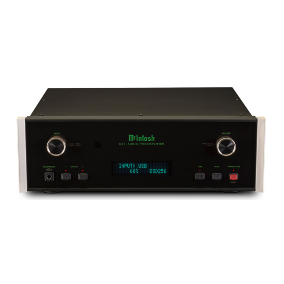
- Page 1 McIntosh Laboratory, Inc. 2 Chambers Street Binghamton, New York 13903-2699 Phone: 607-723-3512 www.mcintoshlabs.com Audio Preamplifier Owner’s Manual...
-
Page 2: Safety Instructions
he lightning flash with arrowhead, within an equilateral triangle, The exclamation point within an equilateral triangle is intended to is intended to alert the user to the presence of uninsulated “dan- alert the user to the presence of important operating and mainte- gerous voltage”... -
Page 3: Table Of Contents
Thank You Customer Service Front Panel: Your decision to own this McIntosh C47 Audio Pre- If it is determined that your McIntosh product is in amplifier ranks you at the very top among discrimi- need of repair, you can return it to your Dealer. You Front Panel Displays, Controls, Push-buttons and Jack .............. -
Page 4: General Information
McIntosh Power Amplifiers. A to the C47 Audio Preamplifier. ponents. For additional information go to www. 3.5mm stereo mini phone plug is Power 2. The Main AC Power going to the C47 and any mcintoshlabs.com. used for connection to the Power Control Meter other McIntosh Component(s) should not be applied 8. -
Page 5: Introduction
Fully regulated Power Supplies and a special R-Core the other for Moving Magnet Cartridges. Both phono 12dB of boost or cut. The C47 remembers the Bass Power Transformer ensure stable noise free operation inputs have selectable loading. The circuits use the and Treble Setting for each input. -
Page 6: Dimensions
Dimensions Dimensions The following dimensions can assist in determining the best location for your C47. There is additional information on the next page pertaining to installing the C47 into cabinets. Front View of the C47 " 44.4cm " 6" 13.7cm 15.2cm... -
Page 7: Installation
Installation Installation " 3/16 The C47 can be placed upright on a table or shelf, 43.7cm standing on its four feet. It also can be custom in- stalled in a piece of furniture or cabinet of your C47 Front Panel choice. -
Page 8: Connections
C47 Remote Control HR085. With an external sensor connected to the C47, remote control operation of the system is possible from another room and/or when the C47 is located in a cabinet with the doors closed. The connection instructions below, together with the C47 Input/Output/Control Connection Diagrams located on the separate folded sheets “Mc1A/1B and... - Page 9 18. Connect the Audio Cables coming from the Turn- Data Control Connections: 26. Connect the C47 to a live AC Outlet using the sup- table to the C47 MC PHONO INPUT Jacks. 9. Connect a Control Cable from the C47 DATA plied Power Supply Cord.
-
Page 10: Hr085 Remote Control Push-Buttons
Tuner scans Up the dial to for the next selection SEEK the next Station Selects Previous Tuner Station PRESET Tuner scans Down the dial to SEEK the next Station Note: Push-buttons whose function is not identified above are for use with other McIntosh Products. -
Page 11: How To Use The Hr085 Remote Control
McIntosh Source Components connected to the C47 via the Data Ports. Notes: 1. If at any time the C47 seems unresponsive to the HR085 Remote Control Commands, press DEVICE Push-button to select first. -
Page 12: Front Panel Displays, Controls, Push-Buttons And Jack
TONE Push-button with indicator, when de- STANDBY/ON Push-button OUTPUT 1 and 2 Push-buttons activated the audio signal bypasses the Trim with indicator, switches the C47 with indicators, switch the Tone Controls ON or OFF (Standby) and resets Preamplifier Outputs 1 and 2... -
Page 13: Setup
Default Settings PUTS Off (or back On if they have been previously Note: If the C47 is currently On, proceed to step 2. The Default Settings Chart below indicates the Func- switched Off). The default INPUT Names can be 1. -
Page 14: Rename Input
< nent connected (refer to page 9, step 15). the character “B” to “M”. Refer to figure 9. The C47 Default Input Names (UNBAL 1, BAL 1, Figure 13 COAX 1, etc.) as indicated on the Front Panel Dis- RENAME: BAL 1... -
Page 15: Output Settings
Setup, con’t Output Settings The Output Settings provide the ability to change how SETUP: OUTPUT 2 RENAME: BAL 1 the C47 Output 1, Output 2 and Headphones function. Switched >MEDIA < OUTPUT 1 and 2: Figure 24 Figure 15 By defaut OUTPUT 1 and 2 are set to go On/Off by... -
Page 16: Power Control Triggers 1 And 2
2 is selected. Both Triggers can also be reassigned control of the source component using the C47 sup- to a given Input or Inputs or go On/Off with the C47 plied HR085 Remote Control. By default, all of the Figure 32 The second example will use selection of Trigger 2 to power. -
Page 17: Passthru
Decoder can “Passthru” the C47 and onto its associ- and 1 stop bit) with other equipment is adjustable are used when the C47 is used in the same location as from 9,600 bits per second to 115,200 bits per second. -
Page 18: Operation
IR Sensor Power Mode Factory Reset The C47 Front Panel Sensor, which receives the sig- The C47 incorporates an Auto Off Feature, which If it becomes desirable to reset all the adjustable set- nals from the HR085 Remote Control, can be switched... - Page 19 Notes...
-
Page 20: How To Operate The C47
Refer to BALANCE Trim Functions figures 60, 61, 62 and 63. To switch OFF the C47 press Listening balance varies with The C47 has nine different Trim Selections with the STANDBY/ON Push-button on the Front Panel or different program sources, room Adjustments. - Page 21 LEVEL + / - Push-buttons to increase (refer to fig- Information Display. Refer to figure 70. The C47 allows the adjustment of levels for each of the ure 74) or decrease (refer to figure 75) the volume Source Inputs for the same relative volume. To adjust level of the low frequencies.
-
Page 22: Tone Controls
Display returns to indicate the Source Selection and Figure 77 Figure 79 Volume Level. Notes: 1. Control of Meter Illumination via the C47 for recent McIntosh Power Amplifiers requires a power control cable connection between the Power Amplifier and C47. -
Page 23: Mute
After approximately 6 seconds the Information except the FIXED OUTPUT. The Front Panel Infor- the C47. To stop the Audio and Power Control Signals Display returns to indicate the Source Selection and mation Display will indicate the Source Name and from going to the separate Power Amplifiers, press the Volume Level. -
Page 24: Optical And Digital Inputs
INPUT UP / DOWN Push-button on the ple® Macintosh® Computers using OS-10.6.8 or later. Figure 87 The C47 OUTPUT 1 and 2 along with the TONE Remote Control. When using a PC Computer with Windows, a spe- Front Panel Push-buttons are active when in the 2. - Page 25 Installing the Software Windows Sound Settings It is important to first install the downloaded software For proper operation of the McIntosh Product via the Computer USB Connection, it is required to make on your computer before connecting the McIntosh Product to the computer. The USB Driver is included changes to Windows Sound Settings: 1.
-
Page 26: Usb Music Playback
“JRiver Media Center”. Rate (refer to figures 107 and 108 for PCM Signals). Reset of Microprocessors INPUT: USB In the unlikely event the controls of the C47 stop func- 44.1kHz tioning, the microprocessors can be reset by perform- Figure 107 ing the following: 1. - Page 27 How to Operate the C47, con’t 2. To switch the C47 back On, press the STANDBY/ ON Push-button. Note: This can be performed with the C47 On or in the Standby Mode.
-
Page 29: Photos
Photos... -
Page 30: Specifications
240 Volts, 50/60Hz at 30 watts Phono MC, 0.45mV Standby Power, less than 0.5 watts 100 ohms Unbalanced Note: Refer to the rear panel of the C47 for the correct 200 ohms Balanced voltage. Signal To Noise Ratio (A-Weighted) High Level - 100dB (Below rated output) -
Page 31: Packing Instruction
017937 Plastic foot needed, please call or write Customer Service Depart- 400159 #10-32 x 3/4” screw ment of McIntosh Laboratory. Refer to page 3. Please 404080 #10 Flat washer see the Part List for the correct part numbers. FOAM PLUG... - Page 32 McIntosh Laboratory, Inc. 2 Chambers Street Binghamton, NY 13903 www.mcintoshlabs.com The continuous improvement of its products is the policy of McIntosh Laboratory Incorporated who reserve the right to improve design without notice. Printed in the U.S.A. McIntosh Part No. 04157700...
Need help?
Do you have a question about the C47 and is the answer not in the manual?
Questions and answers
I cannot get the MCT out of the silent mode, which happened suddenly between usage with my Mcintosh C47 preamp