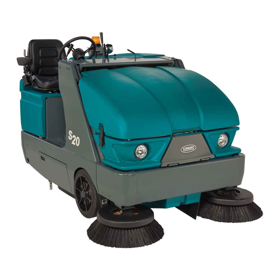
Tennant S20 Operator's Manual
Sweepmax system
shakemax 360
tennanttrue parts
iris a tennant technology
Hide thumbs
Also See for S20:
- Service information manual (86 pages) ,
- Operator's manual (80 pages) ,
- Instruction bulletin (10 pages)
Table of Contents
Advertisement
Quick Links
Advertisement
Table of Contents

Related Manuals for Tennant S20


Summary of Contents for Tennant S20
- Page 1 (Battery) Sweeper Operator Manual SweepMaxt System ShakeMaxt 360 TennantTrue Parts IRIS a Tennant Technology North America / International 9006704 For the latest Parts manuals and other Rev. 04 (4−2014) language Operator manuals, visit: *9006704* www.tennantco.com/manuals...
- Page 2 Installation Date − INTENDED USE The S20 is an industrial rider machine designed to sweep hard surfaces (concrete, asphalt, stone, synthetic, etc). Typical applications include industrial warehouses, manufacturing facilities, distribution facilities, stadiums, arenas, convention centers, parking facilities, transportation terminals, and construction sites. Do not use this machine on soil, grass, artificial turf, or carpeted surfaces.
-
Page 3: Table Of Contents
..... . Storage Information ....S20 Electric 9006704 (4−2014) - Page 4 Index ........S20 Electric 9006704 (4−2014)
-
Page 5: Important Safety Instructions − Save These
Tennant − Use brakes to stop machine. representative for information on how to − Go slowly on inclines and slippery disable the cellular communication surfaces. -
Page 6: Safety Precautions
SAFETY PRECAUTIONS − Use care when reversing machine. − Use Tennant supplied or approved − Move machine with care when hopper replacement parts. is raised. − Do not disconnect the off−board − Make sure adequate clearance is charger’s DC cord from the machine available before raising hopper. - Page 7 WARNING LABEL − Moving belt and fan. Stay away. WARNING LABEL − Machine can emit excessive noise. Hearing loss can result. Wear hearing protection. Located on belt guard. Located only on machines with cab option. 354590 S20 Electric 9006704 (4−2014)
- Page 8 Located on the side of the operator compartment. Located on back of main electrical panel. WARNING LABEL − Accident may occur. Do not operate vacuum wand while driving. Located on the optional vacuum wand. 354590 S20 Electric 9006704 (4−2014)
-
Page 9: Operation
OPERATION OPERATION MACHINE COMPONENTS 1. Operator seat 6. Brush door 2. Steering wheel 7. Batteries 3. Instrument panel 8. Hopper access door 4. Hopper cover 9. Main cover 5. Side brush S20 Electric 9006704 (8−2009) -
Page 10: Controls And Instruments
23. Right side brush adjustment knob Thermo−Sentry 24. Left side brush adjustment knob 11. Clogged dust filter light (Dual side brush option only) 12. Hopper door closed light 25. Main cover lever 13. Clogged hydraulic filter light S20 Electric 9006704 (8−2009) -
Page 11: Symbol Definitions
Main brush down and on Side brush up and off Main brush up and off Operating lights Battery charging system Hazard light Clogged dust filter Side brush pressure Thermo−Sentry Parking brake Hopper door closed (light) Clogged hydraulic filter S20 Electric 9006704 (8−2009) - Page 12 Circuit breaker #8 Circuit breaker #9 Circuit breaker #10 Circuit breaker #11 Circuit breaker #12 Circuit breaker #13 Circuit breaker #14 Circuit breaker #15 Circuit breaker #16 Circuit breaker #17 Circuit breaker #18 Circuit breaker #19 S20 Electric 9006704 (8−2009)
-
Page 13: Installing Batteries
3. With adequate assistance carefully install the batteries into the battery compartment tray and arrange the battery posts as shown. NOTE: For large traction batteries, use a hoist to install the battery. Front of machine S20 Electric 9006704 (4- -2014) -
Page 14: Operation Of Controls
PARKING BRAKE LIGHT The parking brake light comes on when the parking brake is engaged. Release the parking BRAKE PEDAL brake before operating the machine. Press the Brake pedal to stop the machine. S20 Electric 9006704 (8−2009) -
Page 15: Main Cover Lever
SIDE BRUSH PATTERN section of this manual. NOTE: The side brush adjustment knob can be repositioned. Lift the knob, turn it to the desired position, and release it. S20 Electric 9006704 (8−2009) -
Page 16: Clogged Dust Filter Light
Thermo−Sentry will also move the vacuum and filter shaker lever to the Vacuum fan off position. If this happens, stop the machine, eliminate the source of the heat, and return the lever to the Vacuum fan on position. S20 Electric 9006704 (8−2009) -
Page 17: Power Kill Switch
Operate the machine a few minutes before reading the charge level of the batteries. NOTE: The battery discharge indicator will not reset from the flashing indicator unless the batteries have been fully charged. S20 Electric 9006704 (8−2009) -
Page 18: Operator Seat
The operator’s weight adjustment lever controls the seat weight adjustment. The lever has three positions: lightweight, middleweight, and heavyweight. SEAT BELTS (OPTION) FOR SAFETY: Before starting machine, adjust seat and fasten seat belt (if equipped). S20 Electric 9006704 (8−2009) -
Page 19: How The Machine Works
NOTE: The amount and type of soilage play an important role in determining the type of brushes to use. Contact a Tennant representative for specific recommendations. Polypropylene Sand Wedge Main Brush − Recommended for heavy accumulation of sand and other fine particles. -
Page 20: While Operating The Machine
17.6% grade. Do not operate machine in areas where the ambient temperature is above 43_ C (110_ F). Do not operate sweeping functions in areas where the ambient temperature is below freezing 0_ C (32_ F). S20 Electric 9006704 (4−2014) -
Page 21: Pre−Operation Checklist
- Check all controls for proper operation. - Check the hopper skirts and seals for damage and wear. - Check the brakes and steering for proper operation. - Check the service records to determine maintenance requirements. S20 Electric 9006704 (4−2014) -
Page 22: Starting The Machine
FOR SAFETY: When starting machine, keep foot on brake and directional pedal in neutral. 2. Turn on the machine. 3. Release the machine parking brake. 4. Drive the machine to the area to be cleaned. S20 Electric 9006704 (8−2009) -
Page 23: Turning Off The Machine
NOTE: The machine will coast for a short distance when your foot is removed from the directional pedal. Use the brake pedal to stop the machine. 3. Set the machine parking brake. S20 Electric 9006704 (4−2014) -
Page 24: Sweeping
5. Place the side brush lever in the left Side brush down and on position. The brush will automatically start rotating. NOTE: The vacuum fan duct should be off when sweeping wet debris. 6. Sweep as needed. S20 Electric 9006704 (8−2009) -
Page 25: Stop Sweeping
2. Place the main brush lever in the left Main brush up and off position. 3. Pull and hold the hopper door lever back until the hopper door closed light comes on. S20 Electric 9006704 (8−2009) -
Page 26: Emptying The Hopper
Make sure adequate clearance is available before raising hopper. NOTE: Be aware that the minimum ceiling height needed to high dump the hopper is 2490 mm (98 in). S20 Electric 9006704 (8−2009) - Page 27 Vacuum fan on position. FOR SAFETY: When using machine, use care when reversing machine. 10. Push and hold the hopper raise / lower lever forward to lower the hopper. Release the lever into the Hold position. S20 Electric 9006704 (8−2009)
-
Page 28: Engaging Hopper Support Bar
NOTE: Be aware that the minimum ceiling height needed to high dump the hopper is 2490 mm (98 in). 4. Lower and position the hopper support bar onto the support bar stop. WARNING: Raised hopper may fall. Engage hopper support bar. S20 Electric 9006704 (8−2009) -
Page 29: Disengaging Hopper Support Bar
2. Pull and hold the hopper raise / lower lever back and raise the hopper slightly. Release the lever into the Hold position. 3. Put the support bar in its storage position WARNING: Lift arm pinch point. Stay clear of hopper lift arms. S20 Electric 9006704 (8−2009) - Page 30 OPERATION 4. Push and hold the hopper raise / lower lever forward to lower the hopper. Release the hopper lever into the Hold position. 5. Shut the machine off. S20 Electric 9006704 (8−2009)
-
Page 31: Options
8. Turn on the machine power. 9. Pull and hold the hopper door lever back until the hopper door closed light comes on. 5. Connect the vacuum hose to the vacuum wand. S20 Electric 9006704 (4−2014) -
Page 32: Tower Bumpers (Option)
16. Disconnect the vacuum hose from the vacuum wand. 17. Put the vacuum wand in the mounting clips and hose into the storage compartment. 18. Close the hopper cover. 3. Close and secure the tower bumpers before operating the machine. S20 Electric 9006704 (8−2009) -
Page 33: Machine Troubleshooting
Recirculation flap damaged Replace flap Wrong sweeping brush Contact TENNANT representative for recommendations Hopper lip skirts worn or damaged Replace lip skirts Side brush drive failure Contact TENNANT service personnel Main brush drive failure Contact TENNANT service personnel S20 Electric 9006704 (1−2010) -
Page 34: Maintenance
50 hours only) Rear wheel Torque wheel nuts (after ini- − tial 50 hours only) Propelling gearbox Change gear lubricant (after initial 50 hours only) Change fill-level plug seals − (after initial 50 hours only) S20 Electric 9006704 (4−2014) - Page 35 ..SAE 90 Gear lubricant HYDO TennantTrue premium hydraulic fluid or equivalent . . . Special lubricant, Lubriplate EMB grease (TENNANT part no. 01433−1) NOTE: More frequent intervals may be required in extremely dusty conditions. S20 Electric 9006704 (4−2014)
-
Page 36: Lubrication
Fill the second grease fitting while rotating the gearbox back to the original position. The bearing cavity is full when grease comes out of the top seal. 05934 S20 Electric 9006704 (4−2014) -
Page 37: Hopper Lift Arm Pivots
ATTENTION! Do not overfill the hydraulic fluid reservoir or operate the machine with a low level of hydraulic fluid in the reservoir. Damage to the machine hydraulic system may result. S20 Electric 9006704 (4−2014) -
Page 38: Hydraulic Fluid
3.8 L (1 gal) 1057708 19 L (5 gal) If using a locally−available hydraulic fluid, be sure the specifications match the Tennant hydraulic fluid specifications. Substitute fluids can cause premature failure of hydraulic components. ATTENTION! Hydraulic components depend on system hydraulic fluid for internal lubrication. -
Page 39: Batteries
Add distilled water if low. DO NOT OVERFILL. The electrolyte will expand and may overflow when charging. Before Charging After Charging NOTE: Make sure the battery caps are in place while charging. S20 Electric 9006704 (4−2014) -
Page 40: Charging The Batteries (Off−Board Charger)
4. Plug the charger AC power supply cord into a when the batteries are plugged into the charger, properly grounded outlet. refer to the charger manufacturer manual for fault code definitions. 5. Unplug the battery connector from the machine connector. S20 Electric 9006704 (4- -2014) - Page 41 MAINTENANCE 7. The Tennant charger will start automatically. 9. Reconnect the battery connector to the When the batteries are fully charged, the machine connector. Tennant charger will automatically turn off. 6 x 6V NOTE: Use a charger with the proper rating for the batteries to prevent damage to the batteries or reduce the battery life.
-
Page 42: Fuses , Relays, And Circuitbreakers
36 VDC, 100 A Main contactor 36 VDC, 100 A Hydraulic pump 36 VDC, 100 A Forward 36 VDC, 100 A Reverse 36 VDC, 100 A Backup alarm / light 36 VDC, 100 A Filter shaker 36 VDC, 100 A Thermo−Sentry S20 Electric 9006704 (4−2014) -
Page 43: Circuit Breakers
2.5 A Extra spare #2 CB-17 Flasher (option) CB-18 − Not used CB-19 − Not used ELECTRIC MOTORS The carbon brushes on the propelling and accessories motors should be inspected after every 800 hours of machine operation. S20 Electric 9006704 (8−2009) -
Page 44: Belts
Check the vacuum fan belt tension and wear after every 200 hours of operation. The correct tension is when the belt deflects 4 mm (0.16 in) from a force of 0.7 kg (1.5 lb) at belt midpoint. S20 Electric 9006704 (4−2014) -
Page 45: Hopper Dust Filter
5. Clean dust and debris from the dust filter tray. prop rod. 6. Reinstall the dust filter. 2. Remove the dust filter cover. 7. Reinstall the dust filter cover. 8. Close the hopper cover. S20 Electric 9006704 (4−2014) -
Page 46: Cleaning The Hopper Dust Filter
NOTE: It is not necessary to remove the cyclone nozzle closer than 50 mm (2 in) to the filter. assembly from the machine to check / clean the seals. FOR SAFETY: When servicing machine, wear eye and ear protection when using pressurized air. S20 Electric 9006704 (4−2014) -
Page 47: Cyclone Perma−Filter
HOPPER DUST FILTER COVER SEAL Check the hopper dust filter cover seal for wear or damage every 100 hours of operation. Clean dust and debris from the seal as necessary. S20 Electric 9006704 (8−2009) -
Page 48: Main Brush
Refer to CHECKING THE MAIN BRUSH PATTERN. 2. Open the right side main brush access door. 3. Loosen the brush idler plate T−bolt. Remove the brush idler arm assembly. S20 Electric 9006704 (4−2014) -
Page 49: Checking The Main Brush Pattern
FOR SAFETY: Before leaving or servicing brush idler plate. machine, stop on level surface, set parking brake, turn off machine, and remove key. 4. If the brush pattern is tapered, see ADJUSTING THE MAIN BRUSH TAPER section of this manual. 00601 S20 Electric 9006704 (4−2014) -
Page 50: Adjusting The Main Brush Width
5. Insert the side brush retaining pin through the side brush hub and shaft. 6. Secure the pin by clipping the pin keeper over the end of the pin. 7. Adjust the side brush pattern with the side brush down pressure knob. S20 Electric 9006704 (4−2014) -
Page 51: Adjusting The Side Brush Pattern
The side brush front to rear tilt is adjusted with the side brush cable and clevis pin. SIDE BRUSH GUARD Rotate the side brush guard 90_ after every 200 hours of operation, or sooner if worn. Replace the brush guard after using all four sides. S20 Electric 9006704 (4−2014) -
Page 52: Skirts, Flaps, And Seals
The hopper side skirt should clear the Check the skirts for wear or damage and floor by 3 mm (0.12 in). adjustment daily. Check the hopper side skirt for wear or damage and adjustment daily. S20 Electric 9006704 (4−2014) -
Page 53: Skirts (Option)
Check the seal for wear or damage after every 100 hours of operation. Check the seals for wear or damage after every 100 hours of operation. S20 Electric 9006704 (8−2009) -
Page 54: (Option − Vacuum Wand Only)
HOPPER DOOR SEALS The hopper door seals are located on the hopper door. They seal the hopper when the hopper door is closed. Check the seals for wear or damage after every 100 hours of operation. S20 Electric 9006704 (8−2009) -
Page 55: Brakes And Tires
The distance must be between 12 mm (0.5 in) and 25 mm (1.0 in). Adjust the brakes if required. TIRES All the tires on the machine are solid. Check the front tires after every 100 hours of operation for damage. S20 Electric 9006704 (4−2014) -
Page 56: Pushing, Towing, And Transporting The Machine
AND is 380 mm loading surface is horizontal AND is 380 mm (15 in) or less from the ground. (15 in) or less from the ground. S20 Electric 9006704 (4−2014) -
Page 57: Machine Jacking
Jack machine up at designated locations only. Support machine with jack stands. The rear jacking location is the center of the rear bumper. Front jacking locations are located on the frame directly in front of the front tire. S20 Electric 9006704 (8−2009) -
Page 58: Specifications
IPX3 Values determined as per EN 60335--2--72 Measure Sound pressure level L Sound uncertainty K 1.7 dB 100 dB Sound power level L + Uncertainty K Vibration -- Hand--arm <2.5m/s Vibration -- Whole body <0.5m/s S20 Electric 9006704 (4- -2014) -
Page 59: General Machine Performance
Manual valve controlled HYDRAULIC SYSTEM System Capacity Fluid Type Hydraulic reservoir 10.6 L (2.8 gal) ISO Grade 32 Hydraulic total 12.1 L (3.2 gal) Propelling gearbox 2.6 L (2.7 qt) SAE 90 Gear weight lubricant S20 Electric 9006704 (4- -2014) -
Page 60: Braking System
102 x 410 mm (4 x 16 in) MACHINE DIMENSIONS 1230 mm 1135 mm (48.5 in) (44.7 in) TOP VIEW 2085 mm (82.1 in) 1260 mm (49.5 in) 1085 mm FRONT VIEW (42.7 in) 2090 mm (82.3 in) SIDE VIEW 354901 S20 Electric 9006704 (4−2014) -
Page 61: Index
Side brush adjustment knob, 13 Disengaging hopper support bar, 27 - 29 Side brush dust control skirts, 51 Doors Side brush guard, 49 Brush Side brush pivot, 49 Seals, 51 Skirts, 50 Hopper, Seals, 52 Hopper access, Seal, 51, 52 S20 Electric 9006704 (4−2014) - Page 62 Engaging hopper support bar, 26 − 28 Main brush adjustment, 13 Lift arm pivots, 35 Right side brush adjustment, 13 Lip skirt, 50 Replacing dust filter, 43 − 45 Seals, 51 Side skirt, 50 Temperature, Light, 14 Thermo−Sentry, 14 S20 Electric 9006704 (4−2014)
- Page 63 Maintenance, 32 - 56 Support, 34 Batteries, 37 Rear wheel support, 34 Checking connections / cleaning, 37 Bearings, 34 Checking the electrolyte level, 37 Grease fitting, 34 Charging batteries (off−board charger), 38 Rear Wheel, Torque, 53 Relays, 40 S20 Electric 9006704 (4−2014)
- Page 64 Rear, 50 Wheels, 53 Side brush dust control, 51 While operating the machine, 18 Specifications, 56 - 59 Braking system, 58 Chargers, 57 Electric motors, 57 General Machine Dimensions / Capacities, 56 − Hydraulic system, 57 S20 Electric 9006704 (4−2014)
Need help?
Do you have a question about the S20 and is the answer not in the manual?
Questions and answers