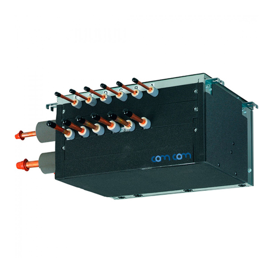
Daikin BS4Q14AV1 Installation Manual

Daikin BS4Q14AV1 Installation Manual

Vrv iv system air conditioners

Advertisement

MODELS
〈BS unit〉
BS4Q14AV1
BS10Q14AV1
BS6Q14AV1
BS12Q14AV1
BS8Q14AV1
BS16Q14AV1
READ THESE INSTRUCTIONS CAREFULLY BEFORE INSTALLATION.
KEEP THIS MANUAL IN A HANDY PLACE FOR FUTURE REFERENCE.
LESEN SIE DIESE ANWEISUNGEN VOR DER INSTALLATION SORGFÄLTIG DURCH.
BEWAHREN SIE DIESE ANLEITUNG FÜR SPÄTERE BEZUGNAHME GRIFFBEREIT AUF.
LIRE SOIGNEUSEMENT CES INSTRUCTIONS AVANT L'INSTALLATION.
CONSERVER CE MANUEL A PORTEE DE MAIN POUR REFERENCE ULTERIEURE.
LEA CUIDADOSAMENTE ESTAS INSTRUCCIONES ANTES DE INSTALAR.
GUARDE ESTE MANUAL EN UN LUGAR A MANO PARA LEER EN CASO DE TENER
ALGUNA DUDA.
PRIMA DELL'INSTALLAZIONE LEGGERE ATTENTAMENTE QUESTE ISTRUZIONI.
TENERE QUESTO MANUALE A PORTATA DI MANO PER RIFERIMENTI FUTURI.
ΙΑΒΑΣΤΕ ΠΡΟΣΕΚΤΙΚΑ ΑΥΤΕΣ ΤΙΣ Ο ΗΓΙΕΣ ΠΡΙΝ ΑΠΟ ΤΗΝ ΕΓΚΑΤΑΣΤΑΣΗ ΕΧΕΤΕ
ΑΥΤΟ ΤΟ ΕΓΧΕΙΡΙ ΙΟ ΕΥΚΑΙΡΟ ΓΙΑ ΝΑ ΤΟ ΣΥΜΒΟΥΛΕΥΕΣΤΕ ΣΤΟ ΜΕΛΛΟΝ.
LEES DEZE INSTRUCTIES ZORGVULDIG DOOR VOOR INSTALLATIE. BEWAAR DEZE
HANDLEINDING WAAR U HEM KUNT TERUGVINDEN VOOR LATERE NASLAG.
LEIA COM ATENÇÃO ESTAS INSTRUÇÕES ANTES DE REALIZAR A INSTALAÇÃO.
MANTENHA ESTE MANUAL AO SEU ALCANCE PARA FUTURAS CONSULTAS.
ПЕРЕД НАЧАЛОМ МОНТАЖА ВНИМАТЕЛЬНО ОЗНАКОМЬТЕСЬ С ДАННЫМИ
ИНСТРУКЦЯМИ. СОХРАНИТЕ ДАННОЕ РУКОВОДСТВО В МЕСТЕ, УДОБНОМ ДЛЯ
ОБРАЩЕНИЯ В БУДУЩЕМ.
MONTAJDAN ÖNCE BU TALİMATLARI DİKKATLİ BİR BİÇİMDE OKUYUN.
GELECEKTE BAŞVURMAK ÜZERE BU ELKİTABINI KORAY ULAŞABİLECEĞİNİZ BİR
YERDE MUHAFAZA EDİN.

INSTALLATION MANUAL

SYSTEM Air Conditioners
English
Deutsch
Français
Español
Italiano
Ελληνικά
Nederlands
Português
Русский
Türkçe

Advertisement

Table of Contents
loading

Summary of Contents for Daikin BS4Q14AV1

  • Page 1: Installation Manual

    INSTALLATION MANUAL English SYSTEM Air Conditioners Deutsch MODELS Français 〈BS unit〉 BS4Q14AV1 BS10Q14AV1 Español BS6Q14AV1 BS12Q14AV1 BS8Q14AV1 BS16Q14AV1 Italiano READ THESE INSTRUCTIONS CAREFULLY BEFORE INSTALLATION. KEEP THIS MANUAL IN A HANDY PLACE FOR FUTURE REFERENCE. Ελληνικά LESEN SIE DIESE ANWEISUNGEN VOR DER INSTALLATION SORGFÄLTIG DURCH.
  • Page 2: Table Of Contents

    BS4Q14AV1 BS10Q14AV1 SYSTEM Air Conditioners Installation manual BS6Q14AV1 BS12Q14AV1 BS8Q14AV1 BS16Q14AV1 CONTENTS 1. SAFETY PRECAUTIONS ....................1 2. BEFORE INSTALLATION ....................3 3. SELECTING INSTALLATION SITE .................5 4. PREPARATIONS BEFORE INSTALLATION ..............6 5. BS UNIT INSTALLATION ....................6 6. REFRIGERANT PIPING WORK ..................7 7.
  • Page 3 • Make certain that all electrical work is carried out by qualified personnel according to the applicable leg- islation (note 1) and this installation manual, using a separate circuit. In addition, even if the wiring is short, make sure to use a wiring that has sufficient length and never connect additional wiring to make the length sufficient.
  • Page 4: Before Installation

    Do not throw away any accessories that may be needed in installation work until installation is complete. Accessory pipes (1) Drain hoses Name Clamps (2) Insulation tube (3) Suction gas HP/LP gas Liquid BS4Q14AV1 1 pc. (f19.1) 1 pc. (f15.9) 23 pcs. 4 pcs. 4 pcs. BS6Q14AV1 1 pc. (f22.2) 32 pcs. 6 pcs.
  • Page 5 • Select the BS unit to fit the total capacity (sum of unit’s capacity) of the indoor units to be connected downstream, refer to the Table 1. About indoor unit’s capacity, refer to the Table 2. Table 1 Model Total capacity of all downstream indoor units BS4Q14AV1 A ≤ 400 BS6Q14AV1 A ≤ 600 BS8Q14AV1 BS10Q14AV1 A ≤...
  • Page 6: Selecting Installation Site

    3. SELECTING INSTALLATION SITE Consider the following requirements when choosing the installation location and obtain the cus- tomer’s consent: • The location must be able to withstand the weight of the BS unit. • The location must allow reliable draining. •...
  • Page 7: Preparations Before Installation

    • Use mold-in inserts and embedded foundation bolts for new installations or hole-in anchor bolts or similar hardware for existing installations, taking care to install in a manner that can withstand the unit’s weight. <Suspension bolt spacing> Unit: mm BS unit BS4Q14AV1 BS6Q14AV1 BS8Q14AV1 BS10Q14AV1 BS12Q14AV1...
  • Page 8: Refrigerant Piping Work

    WARNING • Install the BS unit in a level orientation. Installing the unit in an inclined orientation so that the drain pipe side is higher may result in water leak- age. • Attach nuts on both the top and bottom of the hanging brackets. Overtightening the lower nut without the upper nut in place may cause the hanging bracket and top plate to deform, causing the unit to produce abnormal noise.
  • Page 9 6-1 Pipe size selection Select the size of piping between the outdoor unit (refrigerant branch kit) and the BS unit and between the BS unit and indoor units (refrigerant branch kits) based on example connections 1 and 2 below and Tables 3 through 5.
  • Page 10 Outdoor unit side (*1) Indoor unit side (*2) BS unit Suction pipe HP/LP gas pipe Liquid pipe Gas pipe Liquid pipe ϕ22.2 (ϕ19.1) ϕ19.1 (ϕ15.9) ϕ9.5 BS4Q14AV1 ϕ19.1 (ϕ22.2) ϕ12.7 BS6Q14AV1 ϕ28.6 ϕ19.1 (ϕ22.2, ϕ28.6) ϕ12.7 (ϕ15.9) BS8Q14AV1 ϕ12.7 (ϕ15.9) ϕ6.4 (ϕ9.5) ϕ15.9 BS10Q14AV1 ϕ28.6 (ϕ34.9)
  • Page 11: Piping Connection

    Pressure regulator Location of brazing Taping Nitrogen Valve Refrigerant pipe Fig. 2 CAUTION • Do not use an anti-oxidizing agent when brazing the piping. (Residual debris could clog the piping or cause parts to malfunction.) • For more information about outdoor unit refrigerant pipes, see the installation manual included with the outdoor unit or the Engineering Guide.
  • Page 12: Piping Insulation

    6-5 Piping insulation • After the gas leak inspection is completed, refer to the following figures and use the included insulation tube (3) and clamps (2) to apply the insulation. Liquid pipe BS unit Suction gas pipe HP/LP gas pipe Gas pipe Liquid pipe Indoor unit side...
  • Page 13: Drain Piping Work

    Stopper pipes (accessory(7)) (7)-1 Liquid pipe 3) Use the clamps 3) Use the clamps (7)-2 Gas pipes (accessory(2)) to hold both (accessory(2)) to ends. hold both ends. 1) Attach the insulation tube for stopper pipes. 1) Attach the (accessory(8)) Product Product insulation material.
  • Page 14 • Be sure to use the included drain hose (4) and metal clamp (5). In addition, insert the drain hose (4) all the way onto the drain socket, and tighten the metal clamp (5) in place at the base of the drain socket. (Refer to Fig. 6 and 8.) (Install the metal clamp (5) so that the tightener falls within about 45°, as shown in the figure.) •...
  • Page 15: Electric Wiring Work

    CAUTION • To avoid subjecting the included drain hose (4) to excessive force, do not bend or twist. (Doing so may result in a water leak.) • When using a central drain pipe, follow the instructions in Figure 9. (2) After the completion of piping work, verify that water flows smoothly through the drain. •...
  • Page 16 Table 6 Units Power supply Voltage range Model Type Voltage Min. Max. BS4Q14AV1 BS6Q14AV1 BS8Q14AV1 220-240 BS10Q14AV1 BS12Q14AV1 BS16Q14AV1 MCA: Min. Circuit Amps (A); MFA: Max. Fuse Amps (A) NOTES • The above Table 6 of Electrical Characteristics refers to one BS unit.
  • Page 17: Wiring Example

    8-4 Wiring example Here is shown a wiring example for transmission wiring. WARNING Install an earth leakage circuit breaker. Failure to install an earth leakage circuit breaker may result in electric shock or fire. • Connect terminals F1 and F2 (IN/OUT) on the control Printed Circuit Board in the outdoor unit’s control box to terminals F1 and F2 (outdoor unit) on the first BS unit.
  • Page 18 CAUTION • Use 2-core transmission wiring. Using the same wire with 3 or more cores to connect 2 or more indoor units may cause them to stop with an error. • When the shield wire is used, be sure to ground the one side of the shield wire. The total wiring length is 1500m when shielded wire is used.
  • Page 19: Wiring Connections

    8-5 Wiring connections (Remove the control box cover and connect the wiring as shown in the fi gure below.) Power supply terminal block Turn slightly so that the area near the terminal Turn so that the terminal is is not subject to tensile not subject to tensile force.
  • Page 20 • Power supply wiring and earth wires Remove the control box cover and connect the power supply wiring to the power terminal block (X1M). Also connect the earth wire to the earth wire terminal. Pass both the power supply wires and the earth wire together through the wire through hole (left) into the control box and use the included clamps (2) Cup washer Ring type crimp...
  • Page 21: Initial Setting

    DIP switch setting When not connecting the OFF (Factory default) indoor unit to the A and B branch circuits (A1P) (A2P) (A3P) (A4P) DIP switch No. DS1 (A1P) BS4Q14AV1 BS6Q14AV1 BS8Q14AV1 OFF 1 BS10Q14AV1 Target branch port BS12Q14AV1 BS16Q14AV1 English...
  • Page 22: Adding An Additional Charge Of Refrigerant

    OFF (Factory default) (Example 2) (A1P) (A2P) (A3P) (A4P) DIP switch No. When joining the A and B branches BS4Q14AV1 BS6Q14AV1 DS2 (A1P) BS8Q14AV1 BS10Q14AV1 BS12Q14AV1 OFF 1 Target branch port BS16Q14AV1 When joining branches, only the branch port combinations shown in the above table can be used.
  • Page 23 3P194121-8U EM13A025A (1402) HT...

This manual is also suitable for:

Bs6q14av1Bs10q14av1Bs12q14av1Bs8q14av1Bs16q14av1

Table of Contents