Advertisement
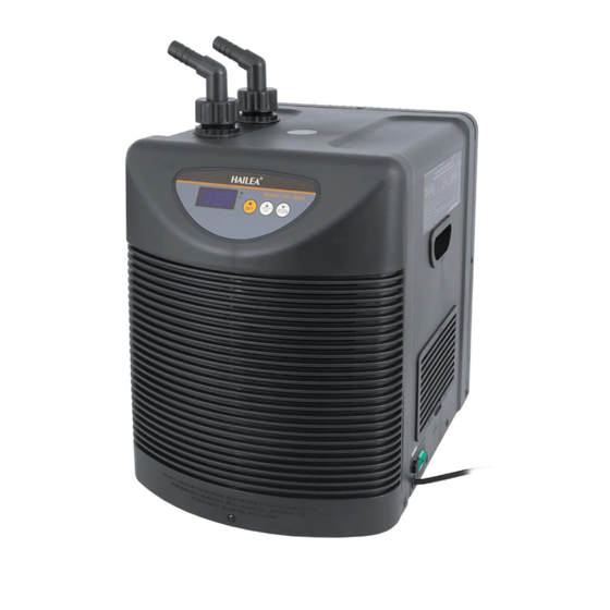
CHILLER COOLER: Models HC-100 A; HC-150A; HC-300A; HC-500A; HC-1000A
PERFORMANCE
1) The scope of the pump must be chosen in relation to the filtering system.
2) The benefits listed in the table is calculated with a temperature of 30 °C, water of 28 °C and with a chilling
16 °C, while the volume of water to refrigerate is 100 lt for the HC-100A, 150 lt for the HC-150A, 300 lt for the
HC-300A, 500 lt for the HC-500A and 1000 lt for the HC-1000A. Of course for an aquarium with a water
capacity less than indicated, the time taken for cooling will be smaller.
3) The temperature reached by cooling is determined by the heating caused by accessories fitted into the
(heater, pump, lighting system, etc ...)
4) The refrigerator must be placed in a ventilated space and <b> not </ b> in support of the aquarium if it is
equipped with doors.
INSTALLATION
When you open the box checked that the product inside is intact with no damage caused by transport or by
accidental falls.
Check carefully that all the pieces needed to be in its machinery, if not talk to your dealer without starting the
installation with any other non-original.
A) contained in its products:
- COOLER
- USER'S EDUCATION
- N ° 4 Wheel CONNECTIONS WITH THE MACHINE FOR PIPES
- N ° 4 O-RING TO BE INSERTED IN CONNECTORS
- N ° 4 BANDS TUBE STOP
- N ° 1 FUSE SPARE (IN MODEL HC-1000A NOT 'NEED AS' THE CIRCUIT NOT NEED TO FUSE)
B) POSITION:
1) Do not install the condenser outside (see fig.1)
Advertisement
Table of Contents


Need help?
Do you have a question about the HC-100 A and is the answer not in the manual?
Questions and answers