Table of Contents
Advertisement
Advertisement
Table of Contents

Related Manuals for Asus Motherboard M2V-MX


Summary of Contents for Asus Motherboard M2V-MX
- Page 1 M2V-MX...
- Page 2 Product warranty or service will not be extended if: (1) the product is repaired, modified or altered, unless such repair, modification of alteration is authorized in writing by ASUS; or (2) the serial number of the product is defaced or missing.
-
Page 3: Table Of Contents
Welcome! ... 1-2 Package contents ... 1-2 Special features ... 1-2 1.3.1 Product highlights ... 1-2 1.3.2 Innovative ASUS features ... 1-4 Before you proceed ... 1-5 Motherboard overview ... 1-6 1.5.1 Motherboard layout ... 1-6 1.5.2 Placement direction ... 1-7 1.5.3... - Page 4 Chapter 2: BIOS setup Managing and updating your BIOS ... 2-2 2.1.1 Creating a bootable floppy disk ... 2-2 2.1.2 ASUS EZ Flash 2 utility ... 2-3 2.1.3 AFUDOS utility ... 2-4 2.1.4 ASUS CrashFree BIOS 2 utility ... 2-6 2.1.5...
- Page 5 Boot Settings Configuration ... 2-35 2.6.3 Security ... 2-36 Tools menu ... 2-40 2.7.1 ASUS EZ Flash 2 ... 2-40 Exit menu ... 2-41 Chapter 3: Software support Installing an operating system ... 3-2 Support CD information ... 3-2 3.2.1 Running the support CD ...
-
Page 6: Canadian Department Of Communications Statement
Notices Federal Communications Commission Statement This device complies with Part 15 of the FCC Rules. Operation is subject to the following two conditions: • This device may not cause harmful interference, and • This device must accept any interference received including interference that may cause undesired operation. -
Page 7: Electrical Safety
Safety information Electrical safety • To prevent electrical shock hazard, disconnect the power cable from the electrical outlet before relocating the system. • When adding or removing devices to or from the system, ensure that the power cables for the devices are unplugged before the signal cables are connected. -
Page 8: M2V-Mx Specifications Summary
Supports Jack-Retasking Technology S/PDIF out support Realtek RTL8100C 10/100 LAN ® Supports up to 8 USB 2.0 ports ASUS EZ Flash 2 ASUS CrashFree BIOS 2 ASUS MyLogo™ ASUS C.P.R. (CPU Parameter Recall) ASUS Q-Fan2 (continued on the next page) - Page 9 BIOS 2.3 WfM 2.0, DMI 2.0, WOL by PME, PXE, RPL, WOR by PME Manageability Drivers Support CD Anti-virus software contents ASUS LiveUpdate Micro-ATX form factor: 9.6 in x 8.6 in Form factor *Specifications are subject to change without notice.
-
Page 11: Chapter 1: Product Introduction
This chapter describes the motherboard features and the new technologies it supports. Product introduction... -
Page 12: Welcome
Thank you for buying an ASUS The motherboard delivers a host of new features and latest technologies, making it another standout in the long line of ASUS quality motherboards! Before you start installing the motherboard, and hardware devices on it, check the items in your package with the list below. -
Page 13: Pci Express™ Interface
USB 1.1. See pages 1-23 and 1-28 for details. 10/100 Mbps LAN Easy connectivity to your network or broadband connection with the onboard LAN port, lets you take gaming online without buying expensive additional LAN cards. See pages 1-22 for details. ASUS M2V-MX... -
Page 14: Innovative Asus Features
ROM chip. See page 2-6 for details. ASUS Q-Fan2 technology The ASUS Q-Fan2 technology smartly adjusts both the CPU and chassis fan speeds according to the system loading to ensure quiet, cool, and efficient operation. -
Page 15: Before You Proceed
This is a reminder that you should shut down the system and unplug the power cable before removing or plugging in any motherboard component. The illustration below shows the location of the onboard LED. M2V-MX M2V-MX Onboard LED ASUS M2V-MX SB_PWR Standby Powered Power... -
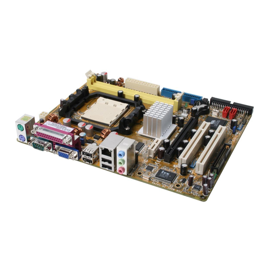
Page 16: Motherboard Overview
Motherboard overview 1.5.1 Motherboard layout PS/2KBMS KBPWR T : Mouse ATX12V B: Keyboard USB12 LAN2_USB34 Super I/O AUDIO RTL8100C ALC883 AAFP 21.8cm (8.6in) CHA_FAN SB_PWR K8M890 M2V-MX PCIEX16 PCI1 PCI2 SPDIF_OUT FLOPPY SATA_E1 SATA_E2 Chapter 1: Product introduction CPU_FAN CR2032 3V Lithium Cell CMOS Power BIOS... -
Page 17: Placement Direction
Place six (6) screws into the holes indicated by circles to secure the motherboard to the chassis. Do not overtighten the screws! Doing so can damage the motherboard. Place this side towards the rear of the chassis ASUS M2V-MX M2V-MX... -
Page 18: Central Processing Unit (Cpu)
Central Processing Unit (CPU) The motherboard comes with a 940-pin AM2 socket designed for the AMD Athlon™ 64 FX/Athlon™ 64 X2/AMD Athlon™ 64/AMD Sempron™ processor. Make sure you use a CPU is designed for the AM2 socket. The CPU fits in only one correct orientation. - Page 19 Connect the CPU fan cable to the CPU_FAN connector on the motherboard. M2V-MX M2V-MX CPU Fan Connector Do not forget to connect the CPU fan connector! Hardware monitoring errors can occur if you fail to plug this connector. ASUS M2V-MX Small triangle Gold triangle CPU_FAN...
-
Page 20: Installing The Heatsink And Fan
1.6.2 Installing the heatsink and fan The AMD AMD Athlon™ 64 FX/ Athlon™ 64 X2/AMD Athlon™ 64/AMD Sempron™ processor require a specially designed heatsink and fan assembly to ensure optimum thermal condition and performance. Make sure that you use only qualified heatsink and fan assembly. Follow these steps to install the CPU heatsink and fan. - Page 21 Push down the retention bracket lock on the retention mechanism to secure the heatsink and fan to the module base. ASUS M2V-MX 1-11...
-
Page 22: System Memory
4 GB system memory when you installed two 2 GB DDR2 memory modules. • For optimum compatibility, we recommend that you obtain memory modules from the same vendor. Visit the ASUS website (www.asus. com) for the latest Qualified Vendors List. 1-12 Chapter 1: Product introduction... -
Page 23: Ddr2 Qualified Vendors List
DDR2 Qualified Vendors List The following table lists the memory modules that have been tested and qualified for use with this motherboard. Visit the ASUS website (www.asus. com) for the latest DDR2 DIMM modules for this motherboard. DDR2 533 Qualified Vendors List... - Page 24 DDR2 667 Qualified Vendors List Size Vendor 512MB Hynix 512MB Hynix 512MB Hynix 512MB CORSAIR 1024MB CORSAIR 256MB ELPIDA 512MB ELPIDA 512MB A-DATA 512MB A-DATA 512MB crucial 1024MB crucial 512MB Apacer 1024MB Apacer 512MB Apacer 512MB Apacer 512MB Kingmax 1024MB Kingmax 512MB Transcend 1024MB Transcend...
- Page 25 A - supports one module inserted in any slot as Single-channel memory configuration B - supports one pair of modules inserted into either slots as one pair of Dual- channel memory configuration Visit the ASUS website (www.asus.com) for the latest memory Qualified Vendor List (QVL). ASUS M2V-MX Side(s)
-
Page 26: Installing A Dimm
1.7.3 Installing a DIMM Unplug the power supply before adding or removing DIMMs or other system components. Failure to do so can cause severe damage to both the motherboard and the components. To install a DIMM: Unlock a DIMM socket by pressing the retaining clips outward. -
Page 27: Expansion Slots
Turn on the system and change the necessary BIOS settings, if any. See Chapter 2 for information on BIOS setup. Assign an IRQ to the card. Refer to the tables on the next page. Install the software drivers for the expansion card. ASUS M2V-MX 1-17... -
Page 28: Irq Assignments For This Motherboard
Standard interrupt assignments Priority – * These IRQs are usually available for ISA or PCI devices. IRQ assignments for this motherboard PCI slot 1 PCI slot 2 When using PCI cards on shared slots, ensure that the drivers support “Share IRQ” or that the cards do not need IRQ assignments; otherwise, conflicts will arise between the two PCI groups, making the system unstable and the card inoperable. -
Page 29: Pci Slots
LAN card installed on a PCI slot. 1.8.4 PCI Express x16 slot This motherboard has supports PCI Express x16 graphic cards that comply with PCI Express specifications. The figure shows a graphics card installed on the PCI Express x16 slot. ASUS M2V-MX 1-19... -
Page 30: Jumpers
Jumpers Clear RTC RAM (CLRTC) This jumper allows you to clear the Real Time Clock (RTC) RAM in CMOS. You can clear the CMOS memory of date, time, and system setup parameters by erasing the CMOS RTC RAM data. The onboard button cell battery powers the RAM data in CMOS, which include system setup information such as system passwords. -
Page 31: Keyboard Power (3-Pin Kbpwr)
500 mA on the +5VSB lead for each USB port; otherwise, the system would not power up. • The total current consumed must NOT exceed the power supply capability (+5VSB) whether under normal condition or in sleep mode. ASUS M2V-MX KBPWR +5VSB (Default) USBPW1-4... -
Page 32: 1.10 Connectors
1.10 Connectors 1.10.1 Rear panel connectors PS/2 mouse port (green). This port is for a PS/2 mouse. Parallel port. This 25-pin port connects a printer, scanner, or other devices. LAN (RJ-45) port. This port allows Gigabit connection to a Local Area Network (LAN) through a network hub. -
Page 33: 1.10.2 Internal Connectors
Pin 5 on the connector is removed to prevent incorrect cable connection when using an FDD cable with a covered Pin 5. M2V-MX M2V-MX Floppy Disk Drive Connector ASUS M2V-MX FLOPPY NOTE: Orient the red markings on the floppy ribbon cable to PIN 1. - Page 34 IDE connectors (40-1 pin PRI_IDE, SEC_IDE) The onboard IDE connectors are for Ultra DMA 133/100/66 signal cable(s). There are three connectors on each Ultra DMA 133/100/66 signal cable: blue, black, and gray. Connect the blue connector to the motherboard’s IDE connector, then select one of the following modes to configure your device(s).
- Page 35 RAID 1, and JBOD configuration through the onboard VIA Plus controller. M2V-MX M2V-MX SATA Connectors For detailed instructions on how to configure RAID 0, 1, and JBOD, refer to the RAID manual in the support CD. ASUS M2V-MX ® SATA1 SATA2 VT8237A 1-25...
- Page 36 JMicron JMB363 (7-pin SATA_E1[black], SATA_E2[black]) These connectors are for Serial ATA signal cables. These connectors support Serial ATA hard disk drives that you can configure for RAID through the onboard Serial ATA RAID controller. The JMicron SATA controller mode item in the BIOS is set to [IDE] by default.
- Page 37 Optical drive audio in connectors (4-pin CD) These connectors allow you to receive stereo audio input from sound sources such as a CD-ROM, TV tuner, or MPEG card. M2V-MX M2V-MX Internal Audio Connector ASUS M2V-MX CPU_FAN PWR_FAN +12V Rotation Right Audio Channel...
-
Page 38: Usb Connectors (10-1 Pin Usb56, Usb78)
USB connectors (10-1 pin USB56, USB78) These connectors are for USB 2.0 ports. Connect the USB module cable to any of these connectors, then install the module to a slot opening at the back of the system chassis. These USB connectors comply with USB 2.0 specification that supports up to 480 Mbps connection speed. -
Page 39: Front Panel Audio Connector (10-1 Pin Aafp)
By default, this connector is set to HD Audio. If you want to connect a AC'97 front panel audio module to this connector, set the Front Panel Support Type item in the BIOS setup to [AC97]. See section 2.4.5 Onboard Device Configuration for details. ASUS M2V-MX Azalia-compliant Legacy AC’97-compliant pin definition... -
Page 40: Atx Power Connectors (24-Pin Eatxpwr, 4-Pin Eatx12V)
ATX power connectors (24-pin EATXPWR, 4-pin EATX12V) These connectors are for an ATX power supply. The plugs from the power supply are designed to fit these connectors in only one orientation. Find the proper orientation and push down firmly until the connectors completely fit. -
Page 41: System Panel Connector
ON turns the system OFF. • Reset button This 2-pin connector is for the chassis-mounted reset button for system reboot without turning off the system power. ASUS M2V-MX SPEAKER PLED PANEL Reset... - Page 42 1-32 Chapter 1: Product introduction...
-
Page 43: Chapter 2: Bios Setup
This chapter tells how to change the system settings through the BIOS Setup menus. Detailed descriptions of the BIOS parameters are also provided. BIOS setup... -
Page 44: Managing And Updating Your Bios
The following utilities allow you to manage and update the motherboard Basic Input/Output System (BIOS) setup. ASUS EZ Flash 2 (Updates the BIOS using a floppy disk, USB Flash, or the motherboard support CD during POST.) ASUS AFUDOS (Updates the BIOS in DOS mode using a bootable floppy disk.) -
Page 45: Asus Ez Flash 2 Utility
2.1.2 ASUS EZ Flash 2 utility The ASUS EZ Flash 2 feature allows you to update the BIOS without having to go through the long process of booting from a floppy disk and using a DOS-based utility. The EZ Flash 2 utility is built-in the BIOS chip so it is accessible by pressing <Alt>... -
Page 46: Afudos Utility
(2) Enter BIOS setup program. Go to the Tools menu to select EZ Flash2 and press <Enter> to enable it. You can switch between drives by pressing <Tab> before the correct file is found. Then press <Enter>. When the correct BIOS file is found, EZ Flash 2 performs the BIOS update process and automatically reboots the system when done. -
Page 47: Updating The Bios File
Updating the BIOS file To update the BIOS file using the AFUDOS utility: Visit the ASUS website (www.asus.com) and download the latest BIOS file for the motherboard. Save the BIOS file to a bootable floppy disk. Write the BIOS filename on a piece of paper. You need to type the exact BIOS filename at the DOS prompt. -
Page 48: Asus Crashfree Bios 2 Utility
2.1.4 ASUS CrashFree BIOS 2 utility The ASUS CrashFree BIOS 2 is an auto recovery tool that allows you to restore the BIOS file when it fails or gets corrupted during the updating process. You can update a corrupted BIOS file using the motherboard support CD, or the floppy disk that contains the updated BIOS file. -
Page 49: Recovering The Bios From The Support Cd
Restart the system after the utility completes the updating process. The recovered BIOS may not be the latest BIOS version for this motherboard. Visit the ASUS website (www.asus.com) to download the latest BIOS file. ASUS M2V-MX... -
Page 50: Asus Update Utility
2.1.5 ASUS Update utility The ASUS Update is a utility that allows you to manage, save, and update the motherboard BIOS in Windows allows you to: • Save the current BIOS file • Download the latest BIOS file from the Internet •... -
Page 51: Updating The Bios Through The Internet
Updating the BIOS through the Internet To update the BIOS through the Internet: Launch the ASUS Update utility from the Windows Start > Programs > ASUS > ASUSUpdate > ASUSUpdate. The ASUS Update main window appears. Select Update BIOS from... -
Page 52: Updating The Bios Through A Bios File
Updating the BIOS through a BIOS file To update the BIOS through a BIOS file: Launch the ASUS Update utility from the Windows clicking Start > Programs > ASUS > ASUSUpdate > ASUSUpdate. The ASUS Update main window appears. Select Update BIOS from a file option from the drop-down menu, then click Next. -
Page 53: Bios Setup Program
The BIOS setup screens shown in this section are for reference purposes only, and may not exactly match what you see on your screen. • Visit the ASUS website (www.asus.com) to download the latest BIOS file for this motherboard. ASUS M2V-MX 2-11... -
Page 54: Bios Menu Screen
2.2.1 BIOS menu screen Menu items Menu bar System Time System Date Legacy Diskette A Primary IDE Master Primary IDE Slave Secondary IDE Master Secondary IDE Slave SATA1 SATA2 IDE Configuration System Information Sub-menu items 2.2.2 Menu bar The menu bar on top of the screen has the following main items: Main For changing the basic system configuration Advanced... -
Page 55: Menu Items
2.2.9 General help At the top right corner of the menu screen is a brief description of the selected item. ASUS M2V-MX System Time [11:10:19] Use [ENTER], [TAB] System Date [Thu 03/27/2003]... -
Page 56: Main Menu
Main menu When you enter the BIOS Setup program, the Main menu screen appears, giving you an overview of the basic system information. Refer to section “2.2.1 BIOS menu screen” for information on the menu screen items and how to navigate through them. System Time System Date Legacy Diskette A... -
Page 57: Primary And Secondary Ide Master/Slave
When set to Disabled, the data transfer from and to the device occurs one sector at a time. Configuration options: [Disabled] [Auto] ASUS M2V-MX Select the type of device connected to the system... -
Page 58: 32Bit Data Transfer [Enabled]
PIO Mode [Auto] Selects the PIO mode. Configuration options: [Auto] [0] [1] [2] [3] [4] DMA Mode [Auto] Selects the DMA mode. Configuration options: [Auto] [SWDMA0] [SWDMA1] [SWDMA2] [MWDMA0] [MWDMA1] [MWDMA2] [UDMA0] [UDMA1] [UDMA2] [UDMA3] [UDMA4] [UDMA5] SMART Monitoring [Auto] Sets the Smart Monitoring, Analysis, and Reporting Technology. -
Page 59: Sata1 And Sata2
Configuration options: [Disabled] [Auto] PIO Mode [Auto] Selects the PIO mode. Configuration options: [Auto] [0] [1] [2] [3] [4] ASUS M2V-MX [Auto] [Auto] [Auto] [Auto] [Auto]... -
Page 60: 32Bit Data Transfer [Disabled]
DMA Mode [Auto] Selects the DMA mode. Configuration options: [Auto] [SWDMA0] [SWDMA1] [SWDMA2] [MWDMA0] [MWDMA1] [MWDMA2] [UDMA0] [UDMA1] [UDMA2] [UDMA3] [UDMA4] [UDMA5] SMART Monitoring [Auto] Sets the Smart Monitoring, Analysis, and Reporting Technology. Configuration options: [Auto] [Disabled] [Enabled] 32Bit Data Transfer [Disabled] Enables or disables 32-bit data transfer. -
Page 61: System Information
: AMD Athlon(tm) 64 X2 Dual Core Processo Speed : 2000MHz Count System Memory Installed Size: 512MB Usable Size : 448MB AMI BIOS Displays the auto-detected BIOS information. Processor Displays the auto-detected processor information. System Memory Displays the auto-detected system memory. ASUS M2V-MX 2-19... -
Page 62: Advanced Menu
Advanced menu The Advanced menu items allow you to change the settings for the CPU and other system devices. Take caution when changing the settings of the Advanced menu items. Incorrect field values can cause the system to malfunction. JumperFree Configuration USB Configuration CPU Configuration Chipset... -
Page 63: Usb Configuration
(OS). Setting to Auto allows the system to detect the presence of USB devices at startup. If detected, the USB controller legacy mode is enabled. If no USB device is detected, the legacy USB support is disabled. Configuration options: [Disabled] [Enabled] [Auto] ASUS M2V-MX [Enable] [Enable] [Enabled]... -
Page 64: Cpu Configuration
Port 64/60 Emulation [Enabled] Allows you to enable or disable the Port 64/60 Emulation.Configuration options: [Disabled] [Enabled]. USB 2.0 Controller Mode [HiSpeed] Allows you to configure the USB 2.0 controller in HiSpeed (480 Mbps) or Full Speed (12 Mbps). Configuration options: [HiSpeed] [Full Speed] BIOS EHCI Hand-Off [Enabled] Allows you to enable or disable the BIOS EHCI hand-off support. -
Page 65: Memory Controller
CAS Latency(CK) TRCD TRAS 2T Mode MCT Timing Mode Bank Interleaving Enable Clock to All DIMMs MemClk Tristate C3/ATLVID Memory Hole Remapping ASUS M2V-MX [Auto] :333 MHz :5.0 :5 CLK :15 CLK :5 CLK :3 CLK :21 CLK :6 ns... - Page 66 Memclock Mode [Auto] Allows you to set the memory clock mode.Set by the code using [Auto] or select [Manual] to set using one of the standard values. Configuration options: [Auto] [Manual] [Limit] CAS Latency (CL) [Auto] Configuration options: [Auto] [3.0] [4.0] [5.0] [6.0] TRCD [Auto] Configuration options: [Auto] [3 CLK] [4 CLK] [5 CLK] [6 CLK] TRP [Auto]...
- Page 67 [2.62ms] [5.24ms] [10.49ms] [20.97ms] [42.00ms] [84.00ms] Power Down Control [Auto] Allows DIMMs to enter power down mode by deasserting the clock enable signal when DIMMs are not in use. Configuration options: [Auto] [Disabled] ASUS M2V-MX [Enabled] [Disabled] [Disabled] [Disabled] 2-25...
-
Page 68: Chipset
2.4.4 Chipset The items in this menu allows you to change the chipset-related features. Select an item then press <Enter> to display the configuration options. Advanced Chipset Settings Warning: Setting wrong values in below sections may cause system to malfunction. K8M890 PCI EXPRESS Congifuration Hyper Transport Configuration K8M890 PCI EXPRESS Configuration... -
Page 69: Onboard Devices Configuration
This item appears only when the Onboard LAN item is set to Enabled. Configuration options: [Disabled] [Enabled] High Definition Audio [Auto] Allows you to disable or set the high definition audio. Configuration options: [Disabled] [Auto] ASUS M2V-MX [Enabled] [SATA] [Enabled] [Disabled]... - Page 70 Front Panel Support Type [HD Audio] Allows you to set the front panel audio connector (AAFP) mode to legacy AC’97 or high-definition audio depending on the audio standard that the front panel audio module supports. Configuration options: [AC97][HD Audio] JMicron SATA/PATA Controller [Enabled] Allows you to enable or disable the JMicron SATA/PATA controller.
-
Page 71: Pci Pnp
ISA graphics device is installed in the system so that the latter can function correctly. Setting to [Disabled] deactivates this feature. Configuration options: [Disabled] [Enabled] ASUS M2V-MX NO: Lets the BIOS configure all the devices in the system. -
Page 72: Power Menu
IRQ xx [Available] When set to [Available], the specific IRQ is free for PCI/PnP devices to use. When set to [Reserved], the IRQ is reserved for legacy ISA devices. Configuration options: [Available] [Reserved] Power menu The Power menu items allow you to change the settings for the Advanced Power Management (APM) feature. -
Page 73: Apm Configuration
When set to [Enabled], this parameter allows you to turn on the system through a PCI LAN or modem card. This feature requires an ATX power supply that provides at least 1A on the +5VSB lead. Configuration options: [Disabled] [Enabled] ASUS M2V-MX [Enabled] [Power Off] [Dusabled]... -
Page 74: Hardware Monitor
Power On By PS/2 Keyboard [Disabled] Allows you to use specific keys on the keyboard to turn on the system. This feature requires an ATX power supply that provides at least 1A on the +5VSB lead. Configuration options: [Disabled] [Space Bar] [Ctrl-Esc] [Power Key] Power On By PS/2 Mouse [Disabled] When set to [Enabled], this parameter allows you to use the PS/2 mouse... - Page 75 Allows you to enable or disable the smart Q-fan control function. When this field is set to [Enabled], the item Smart Fan Mode appears. Configuration options: [Disabled] [Enabled] Smart Fan Mode [Optimal] Sets the smart fan mode. Configuration options: [Performance] [Optimal] [Silent] ASUS M2V-MX 2-33...
-
Page 76: Boot Menu
Boot menu The Boot menu items allow you to change the system boot options. Select an item then press <Enter> to display the sub-menu. Boot Settings Boot Device Priority Boot Settings Configuration Security 2.6.1 Boot Device Priority Boot Device Priority 1st Boot Device 2nd Boot Device 3rd Boot Device... -
Page 77: Boot Settings Configuration
Allows you to enable or disable the full screen logo display feature. Configuration options: [Disabled] [Enabled] Make sure that the above item is set to [Enabled] if you want to use the ASUS MyLogo™ feature. Add On ROM Display Mode [Force BIOS] Sets the display mode for option ROM. -
Page 78: Hit 'Del' Message Display [Enabled]
Hit ‘DEL’ Message Display [Enabled] When set to Enabled, the system displays the message “Press DEL to run Setup” during POST. Configuration options: [Disabled] [Enabled] Interrupt 19 Capture [Disabled] When set to [Enabled], this function allows the option ROMs to trap Interrupt 19. - Page 79 View Only allows access but does not allow change to any field. Limited allows change only to selected fields, such as Date and Time. Full Access allows viewing and changing all the fields in the Setup utility. ASUS M2V-MX <Enter> to change password.
-
Page 80: Change User Password
Change User Password Select this item to set or change the user password. The User Password item on top of the screen shows the default Not Installed. After you have set a password, this item shows Installed. To set a User Password: 1. -
Page 81: Clear User Password
Password Check [Setup] When set to [Setup], BIOS checks for user password when accessing the Setup utility. When set to [Always], BIOS checks for user password both when accessing Setup and booting the system. Configuration options: [Setup] [Always] ASUS M2V-MX 2-39... -
Page 82: Tools Menu
ASUS EZ Flash 2 2.7.1 ASUS EZ Flash 2 Allows you to run ASUS EZ Flash 2. When you press <Enter>, a confirmation message appears. Use the left/right arrow key to select between [Yes] or [Cancel], then press <Enter> to confirm your choice. -
Page 83: Exit Menu
Select this option only if you do not want to save the changes that you made to the Setup program. If you made changes to fields other than System Date, System Time, and Password, the BIOS asks for a confirmation before exiting. ASUS M2V-MX 2-41... -
Page 84: Load Setup Defaults
Discard Changes Allows you to discard the selections you made and restore the previously saved values. After selecting this option, a confirmation appears. Select Yes to discard any changes and load the previously saved values. Load Setup Defaults This option allows you to load the default values for each of the parameters on the Setup menus. -
Page 85: Chapter 3: Software Support
This chapter describes the contents of the support CD that comes with the motherboard package. Software support... -
Page 86: Installing An Operating System
The contents of the support CD are subject to change at any time without notice. Visit the ASUS website(www.asus.com) for updates. 3.2.1 Running the support CD Place the support CD to the optical drive. -
Page 87: Drivers Menu
The drivers menu shows the available device drivers if the system detects installed devices. Install the necessary drivers to activate the devices. ASUS InstAll-Drivers Installation Wizard Installs the ASUS InstAll-Drivers Installation Wizard. AMD Cool ‘n’ Quiet Driver Installs the AMD Cool ‘n’ Quiet driver. -
Page 88: Utilities Menu
Portable Document Format (PDF). ASUS Cool ‘n’ Quiet Utility Installs the ASUS Cool ‘n’ Quiet utility. ASUS Update The ASUS Update utility allows you to update the motherboard BIOS in a Windows environment. This utility requires an Internet connection either ®... -
Page 89: Make Disk Menu
Make JMicron JMB36X 32bit SATA/RAID Driver Allows you to create a JMicron Make JMicron JMB36X 64bit SATA/RAID Driver Allows you to create a JMicron ASUS M2V-MX 9.0c is a multimedia technology that enhances improves the multimedia features ® XP Service Pack 2 already includes Microsoft ®... -
Page 90: Asus Contact Information
3.2.5 ASUS Contact information Click the Contact tab to display the ASUS contact information. You can also find this information on the inside front cover of this user guide. Chapter 3: Software support...
Need help?
Do you have a question about the Motherboard M2V-MX and is the answer not in the manual?
Questions and answers