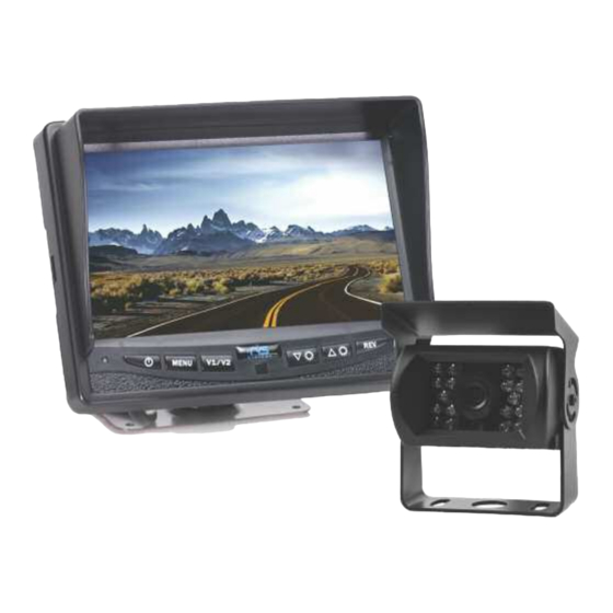
Rear view safety RVS-770613 Product Manual
Hide thumbs
Also See for RVS-770613:
- Product manual instaliation instructions (21 pages) ,
- Product manual (28 pages)
Table of Contents
Advertisement
Advertisement
Table of Contents

Related Manuals for Rear view safety RVS-770613


Summary of Contents for Rear view safety RVS-770613
- Page 2 • 1 3 Channel Multiplexer Control Unit • 1 66’ Camera Cable • 1 Remote Control • 1 Power Connection Wire • 1 Double RCA + Power Converter (to connect external audio, video and power) • 1 Screw Kit for installation REAR VIEW SAFETY...
-
Page 3: Table Of Contents
Table of Contents Introduction ....................4 Safety Information ..................5-7 Before Beginning Installation..............8 Installation Guide..................9 Wiring Camera & Monitor..............10-11 Installation Diagram .................12 Installing the Monitor ................13 Monitor Operation..................14 Splitting & Splicing ...................15 Positioning....................Multiplexer ....................17 Monitor Dimensions..................18 Monitor Specifications................19 Camera Dimensions...................20 Camera Specifications ................21 Troubleshooting..................22 Warranty.......................23... -
Page 4: Introduction
In some jurisdictions, it is unlawful for a person to drive a motor vehicle equipped with a TV viewer or screen located forward of the back of the driver’s seat or in any location that is visible, directly or indirectly, to the driver while operating the vehicle. REAR VIEW SAFETY... -
Page 5: Safety Information
Safety Information Please read the entire manual and follow the instructions and warnings carefully. Failure to do so can cause serious damage and/or injury, including loss of life. Be sure to obey all applica- ble local traffic and motor vehicle regulations as it pertains to this product. - Page 6 Dropping the unit may cause is detected, disconnect the possible mechanical failure. system immediately. • Where the power cable may touch a metal case, cover the cable with a friction tape. A short circuit or disconnected wire may cause a fire. REAR VIEW SAFETY...
- Page 7 Safety Information If you have questions about this product, contact: Customer Service: Rear View Safety 1797 Atlantic Avenue Brooklyn, NY 11233 Tel: 800.764.1028 IN NO EVENT SHALL SELLER OR MANUFACTURER BE LIABLE FOR ANY DIRECT OR CONSEQUENTIAL DAMAGES OF ANY NATURE, OR LOSSES OR EXPENSES RESULTING FROM ANY DEFECTIVE PRODUCT OR THE USE OF ANY PRODUCT.
-
Page 8: Before Beginning Installation
Install split grommets where applicable. Step 3: Once all cables and wiring have been properly routed, perform a system function test by temporarily connecting the system. If the system seems to not be operating properly see troubleshooting (page 22). REAR VIEW SAFETY... -
Page 9: Installation Guide
Installation Guide Camera 1. Attach camera bracket close to rear marker lights, centered on vehicle. 2. Attach camera to bracket using screws provided and adjust the angle. Cable 1. Be sure to position the cable properly. The aviation camera cable uses aircraft grade connectors which means the camera cable can be exposed to all weather elements. -
Page 10: Wiring Camera & Monitor
Camera: Drill a 20mm (0.8in) drain battery. Therefore it is diameter hole into vehicle recommended to connect body near the camera and power to an ignition switched bracket. Insert camera cable into accessory power source. vehicle (be careful not to kink REAR VIEW SAFETY... - Page 11 Wiring Camera & Monitor • Audio works on two ports of Blue and White. multiplexer and positive triggers • There is a built-in voltage must be triggered for audio to regulator for our systems which operate. These are port labeled can handle 12-24 volts.
-
Page 12: Installation Diagram
Installation Diagram Figure 1.1 Figure 1.2 Figure 1.3 Figure 1.4 Connection of Connection of U Flushmount Bracket Bracket REAR VIEW SAFETY... -
Page 13: Installing The Monitor
Installing the Monitor 66ft Extension Cable Monitor Video Out Optional Camera Available 3 Amp Fuse 1. DC12V-24V (red) 2. Ground (black) 3. Port #3 (blue) 4. Port #2 (white) 5. Port #1 (yellow) Camera Reverse With Confidence ™... -
Page 14: Monitor Operation
• To resetpress “MENU” to select. Once selected, use arrows to choose yes or no and press “MENU”. • To returntopreviouspress “REV” when in menu. • To rotatescreenpress “REV”. • To adjust the volumepress “UP” and “DOWN” buttons. REAR VIEW SAFETY... -
Page 15: Splitting & Splicing
Splitting & Splicing Installing sun shield: Put shade cover on the display. Installing back cover: Put the monitor with shade cover in the back cover (only for embedded monitor) Splitting back cover: Hold monitor with 2 hands and detach with fingers, as indicated by arrows. -
Page 16: Positioning
Positioning REAR VIEW SAFETY... -
Page 17: Multiplexer
Multiplexer Port #1 Port #2 Port #3 or DVD Backup Reverse With Confidence ™... -
Page 18: Monitor Dimensions
Monitor Dimensions 7” 5.25” Rotation Imager with sun shade Menu/ Camera (Exit in Down Power Selection Menu Selection Arrow Arrow On/Off Button Mode) power video select down/up menu mirror/ normal image REAR VIEW SAFETY... -
Page 19: Monitor Specifications
Monitor Specifications TFT LCD Digital Monitor Screen Size 7” Dot Resolution x 3 (RGB) x 480 Display Format 16:9 / 500:1 Display Brightness 400cd/m Viewing Angle U:50° / D:60° / R:70° Video Input 3 channel Video Source 1Vp-p, 75 Power Supply DC 12V-24V (+/- 10%) Power Consumption Operating Temperature... -
Page 20: Camera Dimensions
Camera Dimensions 3” 3.25” REAR VIEW SAFETY... -
Page 21: Camera Specifications
Camera Specifications Camera 1/4” Sharp® Color CCD Picture Elements 250,000 pixels Gamma Correction r=0.45 to 1.0 Image Sensor 480TV lines, PAL: 500 NTSC: 510 x 492 Lens 2.1mm View Angle 130° Sync System Internal Synchronization Infrared distance 50 Feet (18 Infrared IR) Usable Illumination 0 Lux (IR On) Power Source... -
Page 22: Troubleshooting
Verify Blue trigger is receiving monitor power • Verify camera is connected to cable Audio on Camera Verify chosen camera has audio Confirm that the Blue audio • • Verify volume setting trigger is connected to 12v+ • REAR VIEW SAFETY... -
Page 23: Warranty
Rear View Safety, Inc. system after partial failure or use with improper accessories. -
Page 24: Disclaimer
In no event shall Rear View Safety and/or its affiliates have any liability for any losses (whether direct... - Page 25 Take Notes ________________________________________ ________________________________________ ________________________________________ ________________________________________ ________________________________________ ________________________________________ ________________________________________ ________________________________________ ________________________________________ ________________________________________ ________________________________________ ________________________________________ ________________________________________ ________________________________________ ________________________________________ ________________________________________ ________________________________________ ________________________________________ Reverse With Confidence ™...
- Page 26 If you have any questions about this product, contact: Rear View Safety, Inc. 1797 Atlantic Avenue Brooklyn, NY 11233 800.764.1028 BETTER CAMERAS. BETTER SERVICE. IT’S OUR GUARANTEE.
Need help?
Do you have a question about the RVS-770613 and is the answer not in the manual?
Questions and answers
I have power but get a message "NO SIGNAL" I live in a rural area and there are no places that service a back up camera. I bought the Motor home used.