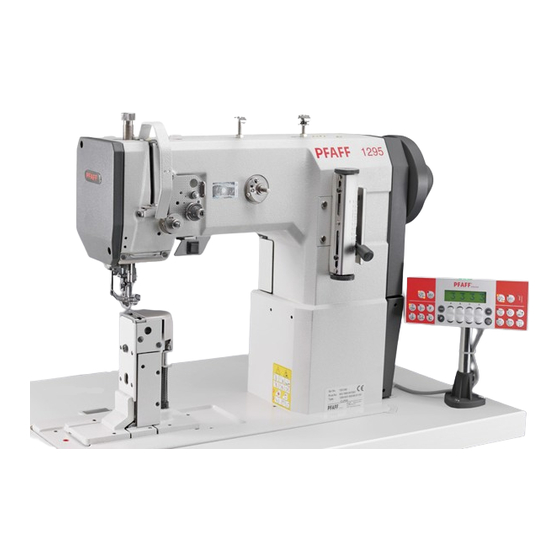
Pfaff 1295 Adjustment Manual
Hide thumbs
Also See for 1295:
- Instruction manual (70 pages) ,
- Instruction manual (42 pages) ,
- Instruction manual (70 pages)
Table of Contents
Advertisement
Quick Links
Download this manual
See also:
Instruction Manual
Advertisement
Table of Contents

Related Manuals for Pfaff 1295


Summary of Contents for Pfaff 1295
- Page 1 ® Industrial 1295 1296 ADJUSTMENT MANUAL This Adjustment Manual is valid for machines from the following serial numbers onwards: # 2 730 099 296-12-18 640/002 Justieranleitung engl. 06.09...
- Page 2 The reprinting, copying or translation of PFAFF Adjustment Manuals, whether in whole or in part, is only permitted with our previous authorization and with written reference to the source. PFAFF Industriesysteme und Maschinen AG Hans-Geiger-Str. 12 - IG Nord D-67661 Kaiserslautern...
-
Page 3: Table Of Contents
Needle-thread tension release ................... 13 - 15 .05.14 Thread check spring, without subclass -900/56 ............13 - 16 .05.15 Thread check spring on the PFAFF 1296 with subclass -900/56 ....... 13 - 17 .05.16 Bobbin winder ......................13 - 18 .05.17 Pressure of the lifting presser ................... -
Page 4: Adjustment
Danger of injury if the machine is started accidentally! For the adjustments in this chapter the PFAFF 1296 two-needle machine is illustrated. On the PFAFF 1295 single-needle machines various adjustments only have to be carried out on one side, i.e. in the right-hand hook area. This is referred to in the different chapters. -
Page 5: Adjusting The Basic Machine
Adjustment Adjusting the basic machine Position of the bottom feed dog crosswise to sewing direction .05.01 Requirement The bottom feed dog must be the same distance from the left and right side of the feed slots. Fig. 11 - 01 Loosen screws 1 and 2. -
Page 6: Adjusting The Bottom Feed Dog In Sewing Direction
Adjustment Adjusting the bottom feed dog in sewing direction .05.02 Requirement With the longest stitch length set, the bottom feed dog must not strike the feed slot at the front or rear end of its stroke. Fig. 11 - 02 Set the longest stitch length. -
Page 7: Bottom Feed Dog Height
Adjustment Bottom feed dog height 05.03 Requirement With the stitch length set at "0" the feed dog must protrude from the needle plate by the height of its teeth when at its highest position. Fig. 11 - 03 Set stitch length „0“. Turn the balance wheel to set the bottom feed dog at its highest position. -
Page 8: Needle Height (Preliminary Adjustment)
Adjustment Needle height (preliminary adjustment) 05.04 Requirement With the needle bar at b.d.c. the clearance between needle bar and needle plate must be 15 mm. Fig. 11 - 04 Re-position the height of needle bar 1 (screws 2) according to Requirement, but do not turn it. -
Page 9: Needle In Needle-Hole Centre
Adjustment Needle in needle-hole centre .05.05 Requirement With the stitch length set at "0" the needle must enter exactly in the centre of the needle hole. Fig. 11 - 05 Remove vibrating presser 1 and lifting presser 2. Set the stitch length at "0" and set the needle bar at t.d.c. Insert a new needle, loosen screws 3, 4, 5 and 6. -
Page 10: Bottom Feed Dog Lifting Motion
Adjustment Bottom feed dog lifting motion 05.06 Requirement 1. With the needle bar at b.d.c. the feed dog must be at its highest position. 2. When the longest stitch length is set and the balance wheel is turned, the bottom feed dog must reach the top side of the needle plate at the same time as the needle. -
Page 11: Feeding Stroke Of Bottom And Top Feeds
Adjustment Feeding stroke of bottom and top feeds .05.07 Requirement With the longest stitch length set and the needle bar at b.d.c. neither the top- nor bottom feed must make any movement when the reverse-feed lever is operated. Fig. 11 - 07 Set the longest stitch length. -
Page 12: Hook Clearance, Needle Rise, Needle Height And Needle Guard
Adjustment Hook clearance, needle rise, needle height and needle guard .05.08 Requirement With the stitch length set at "3" and in needle-rise position (= 1.8 mm past b.d.c. on version "B" or 2.0 mm past b.d.c. on version "C") 1. The hook point must be at the "needle centre" and the clearance between hook and needle 0.05 to 0.1 mm, 2. - Page 13 Adjustment Set the hook point at the needle centre, making sure that the needle is not deflected by needle guard 8. Making sure that bevel gear 6 is not too close, but the hook has not too much play, tighten screws 2. Move fixing collar 7 up against bevel gear 6 and tighten screws 3.
-
Page 14: Top Feed Stroke
Adjustment Top feed stroke .05.09 Requirement With the longest top feed stroke set and the stitch length at "0", lifting presser 1 and vibrating presser 2 must each rise from the needle plate by 7.0 mm when the balance wheel is turned. Fig. -
Page 15: Top Feed Lifting Motion
Adjustment Top feed lifting motion .05.10 Requirement When lifting presser 1 is resting on the needle plate, vibrating presser 4 and needle point 5 must reach the needle plate at the same time at the highest top feed stroke. Fig. 11 - 10 Lower lifting presser 1 onto the needle plate. -
Page 16: Bobbin Case Opener
Adjustment Bobbin case opener .05.11 Requirement The needle thread must neither be trapped between bobbin case opener 3 and hook base 4 nor between position finger 5 and the retainer on the needle plate (see arrows). Fig. 11 - 11 Undscrew and remove post covers 1 (on left post from the rear). -
Page 17: Slip Coupling
Adjustment Slip coupling .05.12 Slip coupling 4 is adjusted at the works. When a thread jams, slip coupling 4 disengages, in order to avoid damage to the hooks. To engage the coupling again, proceed as follows. Fig. 11 - 12 Remove jammed thread. -
Page 18: Needle-Thread Tension Release
Adjustment Needle-thread tension release .05.13 Requirement With the lifting presser raised, there must be a clearance of at least 0.5 mm between tension discs 4. 0.5 mm Fig. 11 - 13 Position pressure plate 1 behind mounting bracket 2 according to Requirement. The clearance of 0.5 mm is a miminum setting and may be as much as 1 mm for heavy threads. -
Page 19: Thread Check Spring, Without Subclass -900/56
Adjustment Thread check spring, without subclass -900/56 .05.14 Requirement The movement of thread check spring 5 must be finished when the needle pointe enters the material (=spring stroke of about 7 mm). Fig. 11 - 14 Adjust stop 1 (screw 2) according to Requirement. To adjust the pressure of the spring, turn screw 3 (screw 4). -
Page 20: Thread Check Spring On The Pfaff 1296 With Subclass -900/56
Adjustment Thread check spring on the PFAFF 1296 with subclass -900/56 .05.15 Requirement The movements of thread check springs 1 and 6 must be finished when the needle points enter the material (=spring stroke of about 7 mm). 8 10 Fig. -
Page 21: Bobbin Winder
Adjustment Bobbin winder .05.16 Requirement 1. With the bobbin winder engaged, drive wheel 1 must be driven reliably. 2. With the bobbin winder disengaged, friction wheel 5 must not run against drive wheel 1. 3. The bobbind winder must switch itself off when the filled thread is about 1 mm from the rim of the bobbin. -
Page 22: Pressure Of The Lifting Presser
Adjustment Pressure of the lifting presser .05.17 Requirement 1. The material must be properly fed, even at the highest sewing speed. 2. There must be no pressure marks on the material. Fig. 11 - 17 Turn screw 1 according to the Requirement. 13 - 19... -
Page 23: Adjusting The Thread Trimmer -900/56
Adjustment Adjusting the thread trimmer -900/56 Engaging solenoid .06.01 Requirement 1. Mounting bracket 1 must be in the middle of its adjusting range and parallel with the right-hand edge of the mounting bracket. 2. When the thread trimmer is in its resting position the core of solenoid 3 must protrude from the solenoid housing by about 4 mm. -
Page 24: Control Cam (Preliminary Adjustment)
Adjustment Control cam (preliminary adjustment) .06.02 Requirement 1. Control cam 1, must be centred with the cutout of bearing mounting 5. 2. With the needle bar at t.d.c., screws 2 must be visible from the front and aligined parallel with the bedplate. Fig. -
Page 25: Control Lever Spring Action
Adjustment Control lever spring action .06.03 Requirement When the thread trimmer is in its resting position, it must be possible to press control lever 3 about 1 mm towards the bedplate (spring action). Fig. 11 - 20 Turn screw 1 (nut 2) according to Requirement. 13 - 22... -
Page 26: Control Lever Stroke
Adjustment Control lever stroke 06.04 Requirement 1. When engaging lever 5 is operated the pin of control lever 6 must drop freely into the track of control cam 7. 2. After thread trimming, control lever 6 must pass freely on the right side of stop plate 3 and engage control lever 5 behind stop plate 3. -
Page 27: Thread-Trimmer Drive Linkage
.06.05 Requirement 1. On the PFAFF 1296 thread-catcher drive linkage 1 must have a length of 128 mm, less half of the needle gauge. On the PFAFF 1295, thread catcher drive linkage 1 must have a length of 128 mm 2. -
Page 28: Linkage Bar (Only On The Pfaff 1296)
Adjustment Linkage bar (only on the PFAFF 1296) .06.06 Requirement The length of linkage bar 1 must be the same as the distance between the two thread- catcher drive shafts 3. Fig. 11 - 23 Adjust middle section 1 (nuts 2) of the linkage bar according to Requirement. -
Page 29: Thread Catcher Height
Adjustment Thread catcher height .06.07 Requirement There must be a clearance of 0.7 mm between the underside of thread catcher 4 and bobbin case cap 5. Fig. 11 - 24 Loosen screws 1 and 2. Adjust the height of shaft 3 according to Requirement. Tighten screws 1. -
Page 30: Thread Catcher Resting Position
Adjustment Thread catcher resting position .06.08 Requirement When the thread trimmer is in its resting poistion there must be a clearance of about 4 mm between the point of catcher 3 and the cutting edge of knife 4. 4 mm Fig. -
Page 31: Knife Pressure
Adjustment Knife pressure .06.09 Requirement When the front edge of thread catcher 3 has passed the knife cutting edge by half, knife 1 must rest with light pressure on the edge of the catcher. Fig. 11 - 26 Adjust knife 1 (screws 2) according to Requirement 13 - 28... -
Page 32: Bobbin Thread Trapping Spring
Adjustment Bobbin thread trapping spring .06.10 Requirement 1. Bobbin thread trapping spring 3 must not be deflected by thread catcher 4 in any phase. 2. After the trimming action the bobbin thread must be securely trapped. 3. It must be possible to insert and remove the bobbin from the hook without any hindrance. Fig. -
Page 33: Control Cam (Final Adjustment)
Adjustment Control cam (final adjustment) .06.11 Requirement The trimming action must be just completed when the take-up lever is at t.d.c. Fig. 11 - 28 Turn control cam 1 (screws 2) according to Requirement. 13 - 30... -
Page 34: Release Lever
Adjustment Release lever .06.12 Requirement When the pin of control lever 3 has dropped into the track of control cam 4 and the needle bar is at b.d.c. there must be a clearance of about 1 mm between control lever 3 and release lever 5. -
Page 35: Release Rod
Adjustment Release rod .06.13 Requirement 1. When the lifting presser is resting on the needle plate, pin 3 must rest at the lower end of the elongated hole in pull-rod 1. 2. The tension discs must not be moved apart in this position. Fig. -
Page 36: Parameter Settings
Adjustment Parameter settings (only on machines with Quick-EcoDrive and control unit P40ED) ● The selection of the user level and the alteration of parameters is described in the separate instruction manual for the drive unit. Parameter list .07.01 Speed for start backtack B, C 300 - 2000 Speed for end backtack... - Page 37 Adjustment Rotating direction of the motor 0 - 1 Proportional sensitivity of the 03 - 24 speed control unit 1295 03 - 24 1296 03 - 24 Variant mini-motor, 1 = long, 2 = short 0 - 1 Additional P- sensitivity of the...
-
Page 38: Circuit Diagrams
Circuit diagrams Circuit diagrams Reference list for the Circuit diagrams Control unit Quick P40 ED Control panel BDF S2 Sewing head recognition system (OTE) Sewing lamp (optional) LED stitch counter Sewing motor Main switch Manual backtacking key S1.1 Pedal speed control unit Needle position change key Single stitch key Start inhibitor (E6 stop) - Page 39 91-191 502-95 Circuit diagram Page 1 Version 07.07.06 14 - 2...
-
Page 40: Circuit Diagram
Circuit diagram 91-191 502-95 Version 07.07.06 Page 2 14 - 3... - Page 41 91-191 502-95 Circuit diagram Page 3 Version 07.07.06 14 - 4...
- Page 42 PFAFF Industriesysteme und Maschinen AG Hans-Geiger-Str. 12 - IG Nord D-67661 Kaiserslautern Telefon: +49 - 6301 3205 - 0 Telefax: +49 - 6301 3205 - 1386 E-mail: info@pfaff-industrial.com Gedruckt in der BRD / Printed in Germany / Imprimé en la R.F.A. / Impreso en la R.F.A...
Need help?
Do you have a question about the 1295 and is the answer not in the manual?
Questions and answers