Table of Contents
Advertisement
Advertisement
Table of Contents

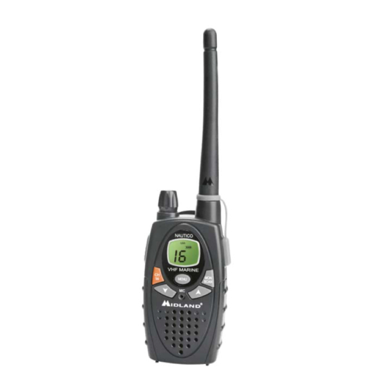
Summary of Contents for Midland Nautico 1
- Page 1 Nautico1 (NT1) Owner’s Guide...
-
Page 2: Table Of Contents
Controls …………………………………………………………. 5 Battery Installation ……………………………………………. 6 Installing the Belt Clip ………………………………………… 6 Charging the Optional Battery Pack ……………………….. 7 Operating Your Radio …………………………………………. 8-11 External Speaker/Microphone Jack ……………………… 11 Troubleshooting Guide ……………………………………… 12 Use and Care ………………………………………………….. 12 Specifications and Frequency Charts …………………….. 13-16 Warranty Information …………………………………………... -
Page 3: Introduction
To maintain compliance with FCC’s RF exposure guidelines, for body-worn operation, this radio has been tested and meets the FCC RF exposure guidelines when used with Midland Radio Corp. accessories supplied or designated for this product. Use of other accessories may not ensure compliance with FCC RF exposure guidelines. -
Page 4: Important Notice, Fcc Licensing
FCC by calling (888) 225-5322. Exposure to Radio Frequency Energy Your Midland radio is designed to comply with the following national and international standards and guidelines regarding exposure of human being to radio frequency electromagnetic energy:... -
Page 5: Lcd Display
6. KEY LOCK ICON – Indicates KEY LOCK mode is on. 7. LOW BATTERY ICON – Indicates battery level is low. 8. WX BAND ICON – Indicates when the radio is in Weather Band mode 9. TRANSMIT POWER LEVEL (Hi / LO) ICON – Indicates TX... -
Page 6: Controls
CONTROLS 10. POWER/VOLUME KNOB – Turn clockwise to turn the power on and increase the volume level. Turn counter-clockwise to decrease the volume level and turn the power off. 11. PTT Button – Press and hold to transmit voice communication. Press twice quickly to send a call tone. -
Page 7: Battery Installation
To install the batteries: 1. With the back of the radio facing you, remove the belt clip (see diagram below) for easy access, then remove the Battery Cover by pressing down on the top center and sliding it down from the radio. -
Page 8: Charging The Optional Battery Pack
Rotate the control counter-clockwise to reduce the volume level and to turn the radio off. During Power On, the radio will beep 3 times with different tones, the LCD will display a "self-test" message for 1... -
Page 9: Transmitting And Receiving
TRANSMITTING AND RECEIVING 1. To transmit a call, hold the radio 2 to 3 inches from your mouth. 2. Press and hold the PTT button and speak in a normal voice into the microphone. The TX icon will appear continuously on the LCD display while transmitting. -
Page 10: Instant Channel
Pressing and holding the MONITOR button for 1 second will let you hear noise so you can adjust the volume level of the radio when not receiving a signal. This should be used to check activity on your current channel before transmitting. -
Page 11: Channel Selection
MENU to move to the next feature setting. ROGER BEEP (end of transmission) TONE When the PTT button is released, the radio will beep to confirm to other users that your transmission has finished. To turn the ROGER BEEP tone on, press the MENU button until the display shows an "rb"... -
Page 12: Call Tone Selection
BAND channels. To confirm, press the PTT button or press MENU to move to the next feature setting. To turn the WEATHER (WX) RECEIVER off, press and hold the MENU button for 3 seconds. The current radio setting will be displayed and the WX BAND icon will go off. -
Page 13: Troubleshooting Guide
3. Do not immerse the radio in water. 4. Use a soft damp cloth to clean the radio 5. Dry the radio with dry lint-free cloth if the radio gets wet. 6. Turn off the radio and remove the batteries during long-term storage. -
Page 14: Specifications And Frequency Charts
SPECIFICATIONS Channels 57 US, 61 CAN, 57 INT10 Weather (WX) Band Channels Operating Frequency VHF 156.025 ~ 162.550 MHz Power Source 4 AA Alkaline or 6.0V Rechargeable NiMH battery pack... - Page 15 FREQUENCY CHART (MHz) Channel Number Frequency MHz INT CAN US 156.050 160.650 01A 156.050 156.050 156.100 160.700 160.750 156.150 156.200 160.800 156.200 156.200 156.250 160.850 05A 05A 156.250 156.250 06 156.300 156.300 156.350 160.950 07A 07A 156.350 156.350 08 156.400 156.400 09 156.450 156.450...
- Page 16 INT CAN US 157.100 161.700 22A 22A 157.100 157.100 157.150 161.750 23A 157.150 157.150 24 157.200 161.800 25 157.250 161.850 26 157.300 161.900 27 157.350 161.950 162.000 28 157.400 156.025 160.625 156.075 160.675 156.075 156.075 156.125 160.725 156.125 156.125 160.775 156.175 63A 156.175 156.175...
- Page 17 INT CAN US 156.925 78A 78A 156.925 156.975 79A 79A 156.975 157.025 80A 80A 157.025 157.075 81A 81A 157.075 157.125 82A 82A 157.125 157.175 83A 83A 157.175 84 157.225 85 157.275 86 157.325 157.375 157.375 157.425 88A 157.425 S= Simplex D= Duplex *= obligatory low transmission power of 1 Watt **= classified to DSC communications...
-
Page 18: Limited Warranty
LIMITED WARRANTY Midland Radio Corporation will repair or replace, at its option without charge, any Midland VHF MARINE transceiver which fails due to a defect in material or workmanship within Three Years following the initial consumer purchase. This warranty does not apply to water damage, battery leak or abuse. -
Page 19: Midland Family Of Products
MIDLAND Family of Products GMRS Weather CB Radio VHF Marine ACCESSORIES Accessories can be purchased at www.midlandradio.com AVP5 - 1 Rechargeable Battery Pack - 1 AC Charger - 1 DC Charger - 1 Mount Holder... - Page 20 MIDLAND RADIO CORPORATION 1120 Clay St. North Kansas City, MO 64116 816.241.8500 www.midlandradio.com Note: Features & Specifications are subject to change without notice. MIDLAND is not responsible for unintentional errors or omissions on its packaging.


Need help?
Do you have a question about the Nautico 1 and is the answer not in the manual?
Questions and answers