Table of Contents
Advertisement
Quick Links
Download this manual
See also:
User Manual
Advertisement
Chapters
Table of Contents

Related Manuals for Asus P5G-TVM


Summary of Contents for Asus P5G-TVM
- Page 1 P5G-TVM...
- Page 2 Product warranty or service will not be extended if: (1) the product is repaired, modified or altered, unless such repair, modification of alteration is authorized in writing by ASUS; or (2) the serial number of the product is defaced or missing.
-
Page 3: Table Of Contents
Contents Notices ....................v Safety information ................vi P5G-TVM specifications summary ............vii Chapter 1: Product introduction Before you proceed .............. 1-2 Motherboard overview ............1-3 1.2.1 Placement direction ..........1-3 1.2.2 Screw holes ............. 1-3 1.2.3 Motherboard layout ..........1-4 1.2.4... - Page 4 Contents 2.2.3 Menu items .............. 2-4 2.2.4 Sub-menu items ............2-4 2.2.5 Configuration fields ..........2-4 2.2.6 Pop-up window ............2-5 2.2.7 General help ............2-5 Main menu ................2-6 2.3.1 System Time ............2-6 2.3.2 System Date ............2-6 2.3.3 Legacy Diskette A ...........
-
Page 5: Notices
Notices Federal Communications Commission Statement This device complies with Part 15 of the FCC Rules. Operation is subject to the following two conditions: • This device may not cause harmful interference, and • This device must accept any interference received including interference that may cause undesired operation. -
Page 6: Safety Information
Safety information Electrical safety • To prevent electrical shock hazard, disconnect the power cable from the electrical outlet before relocating the system. • When adding or removing devices to or from the system, ensure that the power cables for the devices are unplugged before the signal cables are connected. -
Page 7: P5G-Tvm Specifications Summary
P5G-TVM specifications summary LGA775 socket for Intel Pentium 4/Celeron processor ® ® Compatible with Intel Mainstream/Value FMB ® processors Supports Intel Hyper-Threading Technology ® Chipset Northbridge: Intel 915G Graphics Memory and ® Controller Hub (GMCH) Southbridge: Intel 82801FB ICH6 ®... - Page 8 P5G-TVM specifications summary Internal 1 x Floppy disk drive connector connectors 1 x Primary IDE connector 4 x Serial ATA connectors 1 x CPU fan connector 1 x Chassis fan connector 4 x USB 2.0 connectors 1 x 24-pin ATX power connector...
- Page 9 This chapter describes the motherboard features and the new technologies it supports. Product introduction ASUS P5G-TVM...
-
Page 10: Before You Proceed
This is a reminder that you should shut down the system and unplug the power cable before removing or plugging in any motherboard component. The illustration below shows the location of the onboard LED. SB_PWR1 ® P5G-TVM Standby Powered P5G-TVM Onboard LED Power Chapter 1: Hardware information... -
Page 11: Motherboard Overview
Place seven (8) screws into the holes indicated by circles to secure the motherboard to the chassis. Do not overtighten the screws! Doing so can damage the motherboard. Place this side towards the rear of the chassis ® P5G-TVM ASUS P5G-TVM... -
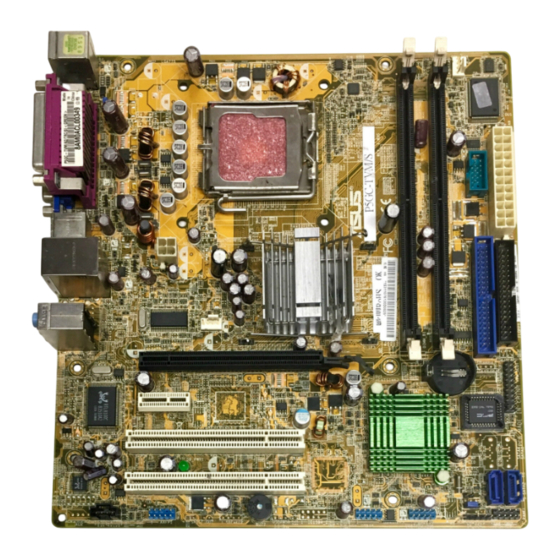
Page 12: Motherboard Layout
Side Speaker Out Below: Center/Subwoofer Top:Line In Center:Line Out Below:Mic In PCIEX16 ® CR2032 3V Lithium Cell PCI1 CMOS Power IR_CON1 ® Intel P5G-TVM SATA4 ICH6 SB_PWR1 PCI2 SATA3 SATA2 TI TSB43AB22A SATA1 PCI3 CLRTC1 ALC655 BUZZ1 PLED1 USB56 IE1394_2... - Page 13 6. Microphone port (pink) 1-22 7. USB 2.0 ports 3 and 4 1-23 8. USB 2.0 ports 1 and 2 1-23 9. Video Graphics Adapter (VGA) port 1-23 10. Serial port 1-23 11. PS/2 keyboard port (purple) 1-23 ASUS P5G-TVM...
- Page 14 Internal connectors Page Floppy disk drive connector (34-1 pin FLOPPY) 1-24 IDE connector (40-1 pin PRI_IDE, SEC_IDE) 1-25 Serial ATA connectors (7-pin SATA1, SATA2) 1-26 CPU and Chassis Fan connectors (4-pin CPU_FAN, 3-pin CHA_FAN) 1-27 USB connectors (10-1 pin USB56, USB78) 1-28 ATX power connectors (24-pin ATXPWR, 4-pin ATX12V) 1-29...
-
Page 15: Central Processing Unit (Cpu)
Contact your retailer immediately if the PnP cap is missing, or if you see any damage to the PnP cap/socket contacts/motherboard components. ASUS will shoulder the cost of repair only if the damage is shipment/transit-related. •... - Page 16 Press the load lever with your thumb (A) and move it to the left (B) until it is released from the retention tab. PnP Cap Retention tab Load lever This side of the cam box should face you. To prevent damage to the socket pins, do not remove the PnP cap unless you are installing a CPU.
- Page 17 Power up the system and enter the BIOS Setup (see Chapter 2: BIOS setup). Under the Advanced Menu, make sure that the item Hyper- Threading Technology is set to Enabled. The item appears only if you installed a CPU that supports Hyper-Threading Technology. Reboot the computer. ASUS P5G-TVM...
-
Page 18: Installing The Cpu Heatsink And Fan
1.3.2 Installing the CPU heatsink and fan The Intel Pentium 4 LGA775 processor requires a specially designed ® ® heatsink and fan assembly to ensure optimum thermal condition and performance. • Install the motherboard to the chassis before you install the CPU fan and heatsink assembly. - Page 19 Connect the CPU fan cable to the connector on the motherboard labeled CPU_FAN1. Do not forget to connect the CPU fan connector! Hardware monitoring errors can occur if you fail to plug this connector. ASUS P5G-TVM 1-11...
-
Page 20: Uninstalling The Cpu Heatsink And Fan
1.3.3 Uninstalling the CPU heatsink and fan To uninstall the CPU heatsink and fan: Disconnect the CPU fan cable from the connector on the motherboard. Rotate each fastener counterclockwise. Pull up two fasteners at a time in a diagonal sequence to disengage the heatsink and fan assembly from the motherboard. - Page 21 Remove the heatsink and fan assembly from the motherboard. Rotate each fastener clockwise to reset the orientation. Narrow end of the groove When reset, each fastener should be oriented as shown, with the narrow groove directed outward. ASUS P5G-TVM 1-13...
-
Page 22: System Memory
Inline Memory Modules (DIMM) sockets. The following figure illustrates the location of the sockets: ® P5G-TVM P5G-TVM 184-pin DDR DIMM sockets 1.4.2 Memory Configurations You may install 256 MB, 512 MB and 1 GB unbuffered non-ECC DDR DIMMs into the DIMM sockets using the memory configurations in this section. - Page 23 Single-channel memory configuration. supports one pair of modules inserted into either the blue slots or the black slots as one pair of Dual-channel memory configuration. Visit the system builderʼs website for the latest DDR Qualified Vendors List. ASUS P5G-TVM 1-15...
-
Page 24: Installing A Dimm
1.4.3 Installing a DIMM Make sure to unplug the power supply before adding or removing DIMMs or other system components. Failure to do so may cause severe damage to both the motherboard and the components. Unlock a DIMM socket by DDR DIMM notch pressing the retaining clips outward. -
Page 25: Expansion Slots
Turn on the system and change the necessary BIOS settings, if any. See Chapter 2 for information on BIOS setup. Assign an IRQ to the card. Refer to the tables on the next page. Install the software drivers for the expansion card. ASUS P5G-TVM 1-17... -
Page 26: Interrupt Assignments
1.5.3 Interrupt assignments Standard interrupt assignments Priority Standard Function System Timer Keyboard Controller Re-direct to IRQ#9 Communications Port (COM2)* Communications Port (COM1)* IRQ holder for PCI steering* Floppy Disk Controller Printer Port (LPT1)* System CMOS/Real Time Clock IRQ holder for PCI steering* IRQ holder for PCI steering* IRQ holder for PCI steering* PS/2 Compatible Mouse Port*... -
Page 27: Pci Slots
The figure shows a LAN card installed on a PCI slot. 1.5.5 PCI Express x16 slot This motherboard supports PCI Express x16 graphic cards that comply with the PCI Express specifications. The following figure shows a graphics card installed on the PCI Express x16 slot. ASUS P5G-TVM 1-19... -
Page 28: Jumpers
Except when clearing the RTC RAM, never remove the cap on CLRTC jumper default position. Removing the cap will cause system boot failure! CLRTC1 ® P5G-TVM Normal Clear CMOS P5G-TVM Clear RTC RAM (Default) 1-20 Chapter 1: Product introduction... - Page 29 +5VSB (Default) ® P5G-TVM P5G-TVM Keyboard power setting Fan power (3-pin FANPWR1) Set this jumper to 1-2 (Default) if you are using a 4-pin CPU fan. Set this jumper to 2-3 if you are using a 3-pin CPU fan. FANPWR1...
-
Page 30: Connectors
Connectors 1.7.1 Rear panel connectors 9 8 PS/2 mouse port (green). This port is for a PS/2 mouse. Parallel port. This 25-pin port connects a parallel printer, a scanner, or other devices. LAN (RJ-45) port. This port allows Gigabit connection to a Local Area Network (LAN) through a network hub. - Page 31 Video Graphics Adapter port. This 15-pin port is for a VGA monitor or other VGA-compatible devices. 10. Serial port. This 9-pin COM1 port is for pointing devices or other serial devices. 11. PS/2 keyboard port (purple). This port is for a PS/2 keyboard. ASUS P5G-TVM 1-23...
-
Page 32: Internal Connectors
PIN 1. ® P5G-TVM PIN 1 P5G-TVM Floppy disk drive connector Power LED connector (3-pin PLED1) This 3-pin connector is for the system power LED. Connect the 3-pin power LED cable from the system chassis to this connector. The LED lights up when you turn on the system power, and blinks when the system is in sleep mode. - Page 33 IDE cable. • Use the 80-conductor IDE cable for Ultra DMA 100/66 devices. PRI_IDE1 NOTE: Orient the red markings (usually zigzag) on the IDE ribbon cable to PIN 1. ® P5G-TVM P5G-TVM IDE connector PIN 1 ASUS P5G-TVM 1-25...
-
Page 34: Serial Ata Connectors (7-Pin Sata1, Sata2)
SATA4 SATA3 SATA2 ® P5G-TVM SATA1 P5G-TVM SATA connectors Important notes on Serial ATA • You must install Windows 2000 Service Pack 4 or the Windows ® ® Service Pack1 before using Serial ATA hard disk drives. -
Page 35: Cpu And Chassis Fan Connectors (4-Pin Cpu_Fan, 3-Pin Cha_Fan)
These are not jumpers! Do not place jumper caps on the fan connectors! CHA_FAN1 CPU_FAN1 ® P5G-TVM P5G-TVM Fan connectors Make sure that your Fan Power (FANPWR1) jumper setting is correct. See page 1-21 for details. ASUS P5G-TVM 1-27... -
Page 36: Usb Connectors (10-1 Pin Usb56, Usb78)
USB 2.0 specification that supports up to 480 Mbps connection speed. ® P5G-TVM USB56 USB78 P5G-TVM USB 2.0 connectors Never connect a 1394 cable to the USB connectors. Doing so will damage the motherboard! The USB module is purchased separately. 1-28 Chapter 1: Product introduction... -
Page 37: Atx Power Connectors (24-Pin Atxpwr, 4-Pin Atx12V)
+5 Volts PSON# Ground Ground +3 Volts -12 Volts P5G-TVM ATX power connectors +3 Volts +3 Volts Important notes on the motherboard power requirements • Do not forget to connect the 4-pin ATX +12 V power plug; otherwise, the system will not boot up. -
Page 38: Front Panel Audio Connector (10-1 Pin Fp_Audio)
® P5G-TVM P5G-TVM Analog front panel connector For motherboards with the optional HD Audio feature, we recommend that you connect a high-definition front panel audio module to this connector to avail of the motherboardʼs high-definition audio capability. -
Page 39: Internal Audio Connector (4-Pin Aux1, Cd1)
CD-ROM, TV tuner, or MPEG card. ® P5G-TVM AUX1 P5G-TVM Internal audio connectors 11. Chassis intrusion connector (4-1 pin CHASSIS) This connector is for a chassis-mounted intrusion detection sensor or switch. Connect one end of the chassis intrusion sensor or switch cable to this connector. -
Page 40: Digital Audio Connector (4-1 Pin Spdif_Out)
(S/PDIF) port(s). Connect the S/PDIF module cable to this connector, then install the module to a slot opening at the back of the system chassis. ® P5G-TVM SPDIF_OUT1 P5G-TVM Digital audio connector The S/PDIF module is purchased separately. 1-32 Chapter 1: Product introduction... -
Page 41: System Panel Connector (10-1 Pin Panel)
PLED PWRSW F_PANEL1 ® P5G-TVM IDE LED RESET P5G-TVM System panel connector • System power LED (2-pin PLED) This 2-pin connector is for the system power LED. Connect the chassis power LED cable to this connector. The system power LED lights up when you turn on the system power, and blinks when the system is in sleep mode. - Page 42 1-34 Chapter 1: Product introduction...
- Page 43 This chapter tells how to change the system settings through the BIOS Setup menus. Detailed descriptions of the BIOS parameters are also provided. BIOS setup...
-
Page 44: Bios Setup Program
BIOS setup program This motherboard supports a programmable firmware chip that you can update using the provided utility. Use the BIOS Setup program when you are installing a motherboard, reconfiguring your system, or prompted to “Run Setup.” This section explains how to configure your system using this utility. Even if you are not prompted to use the Setup program, you can change the configuration of your computer in the future. -
Page 45: Bios Menu Screen
• The BIOS setup screens shown in this chapter are for reference purposes only, and may not exactly match what you see on your screen. • Visit the system builder website to download the latest BIOS information. ASUS P5G-TVM... -
Page 46: Legend Bar
2.2.2 Legend bar At the bottom of the Setup screen is a legend bar. The keys in the legend bar allow you to navigate through the various setup menus. The following table lists the keys found in the legend bar with their corresponding functions. -
Page 47: Pop-Up Window
-/+: Change Value F5: Setup Defaults ESC: Exit →←: Select Menu Enter: Select Sub-menu F10: Save and Exit Pop-up menu 2.2.7 General help At the top right corner of the menu screen is a brief description of the selected item. ASUS P5G-TVM... -
Page 48: Main Menu
[1.44M, 3.5 in.] Legacy Diskette A: Specifies the capacity and physical size of diskette drive A. Primary IDE Master [ST321122A] Primary IDE Slave [ASUS CDS520/A] Secondary IDE Master [None] Secondary IDE Slave [None] HDD SMART Monitoring [Disabled] Installed Memory 256MB... -
Page 49: Primary And Secondary Ide Master/Slave
[Manual]. Configuration options: [CHS] [LBA] [Large] [Auto] Before attempting to configure a hard disk drive, make sure you have the correct configuration information supplied by the drive manufacturer. Incorrect settings may cause the system to fail to recognize the installed hard disk. ASUS P5G-TVM... -
Page 50: Hdd Smart Monitoring
Capacity Displays the auto-detected hard disk capacity. This item is not configurable. Cylinder Shows the number of the hard disk cylinders. This item is not configurable. Head Shows the number of the hard disk read/write heads. This item is not configurable. -
Page 51: Advanced Menu
14 X X TM2 Bus VID 1.2000V Limited CPUID MaxUal [Disabled] Execute Disable Bit [Enabled] F1:Help ↑↓ : Select Item -/+: Change Value F5: Setup Defaults ESC: Exit →←: Select Menu Enter: Select Sub-menu F10: Save and Exit ASUS P5G-TVM... - Page 52 Thermal Management [TM1] The item provides intelligent thermal management by automatically adjusting the CPU multi-frequency and voltage. Configuration options: [TM1] [TM2] TM2 Bus Ratio Displays the Thermal Monitor Bus Ratio. This item is unconfigurable. TM2 Bus VID Displays the Thermal Monitor Bus voltage ID. This item is unconfigurable.
-
Page 53: Memory Configuration
Controls the latency between the DDR SDRAM active command and the read/write command. DRAM RAS# Precharge Controls the idle clocks after issuing a precharge command to the DDR SDRAM. Precharge Delay Sets the row-precharge delay timing. System Memory Frequency Controls the system memory frequency. ASUS P5G-TVM 2-11... -
Page 54: Chipset
2.4.3 Chipset Phoenix-Award BIOS CMOS Setup Utility Advanced Memory Configuration Select Menu Item Specific Help ** VGA Setting ** Place an artificial memory PEG/Onchip VGA Control [Auto] clock limit on On-Chip Video Memory Size the system. Memory is prevented from On-Chip Frame Buffer Size running faster than this FIXED Memory Size... -
Page 55: Pcipnp
Plug and Play devices not required for boot. Configuration options: [No] [Yes] Maximum Payload Size [4096] Allows you to set the PCI Express bus transfer capacity. Configuration options: [128] [256] [512] [1024] [2048] [4096] ASUS P5G-TVM 2-13... -
Page 56: Onboard Device Configuration
2.4.5 Onboard Device Configuration Phoenix-Award BIOS CMOS Setup Utility Advanced Onboard Device Configuration Select Menu Item Specific Help OnChip IDE Device Onboard AC97 Audio [Enabled] Press[Enter] to set Onboard LAN [Enabled] Onboard LAN Boot ROM [Disabled] Serial Port1 Address [3F8/IRQ4] Serial Port2 Address [2F8/IRQ3] Parallel Port Address... - Page 57 Allows you to select the EPP Mode. This item becomes configurable only when the Parallel Port Mode is set to [EPP]. Configuration options: [EPP1.7] [EPP1.9] ECP Mode Use DMA [3] Allows selection of ECP Mode. Configuration options: [1] [3] ASUS P5G-TVM 2-15...
-
Page 58: Usb Configuration
2.4.6 USB Configuration Phoenix-Award BIOS CMOS Setup Utility Advanced USB Configuration Select Menu Item Specific Help USB Controller [Enabled] USB2.0 Controller [Enabled] Enable/Disable USB2.0 and USB Legacy support [Enabled] Legacy Control F1:Help ↑↓ : Select Item -/+: Change Value F5: Setup Defaults ESC: Exit →←: Select Menu Enter: Select Sub-menu... -
Page 59: Power Menu
Allows you to enable or disable the Advanced Configuration and Power Interface (ACPI) support in the Application-Specific Integrated Circuit (ASIC). When set to Enabled, the ACPI APIC table pointer is included in the RSDT pointer list. Configuration options: [Disabled] [Enabled] ASUS P5G-TVM 2-17... -
Page 60: Apm Configuration
2.5.3 APM Configuration Phoenix-Award BIOS CMOS Setup Utility Power Select Menu APM Configuration Power On By PS/2 Keyboard [Any Key] Item Specific Help Restore on AC Power Loss [Power Off] Press [ENTER] to PWR Button < 4 secs [Suspend] select whether or not Power On By PCI Devices [Enabled] to restart the system... - Page 61 When set to [Enabled], this parameter allows you to use the PS/2 mouse to turn on the system. This feature requires an ATX power supply that provides at least 1A on the +5VSB lead. Configuration options: [Disabled] [Enabled] ASUS P5G-TVM 2-19...
-
Page 62: Hardware Monitor
2.5.4 Hardware Monitor The items in this sub-menu displays the hardware monitor values automatically detected by the BIOS. It also allows you to change CPU Q-Fan feature-related parameters. Select an item then press <Enter> to display the configuration options. Phoenix-Award BIOS CMOS Setup Utility Power Select Menu Hardware Monitor... -
Page 63: Boot Menu
Item Specific Help Hard Disk Drives Press[Enter]to set. Network Boot Priority Boot Settings Configuration Security F1:Help ↑↓ : Select Item -/+: Change Value F5: Setup Defaults ESC: Exit →←: Select Menu Enter: Select Sub-menu F10: Save and Exit ASUS P5G-TVM 2-21... -
Page 64: Boot Device Priority
2.6.1 Boot Device Priority Phoenix-Award BIOS CMOS Setup Utility Power Boot Device Priority Select Menu Item Specific Help 1st Boot Device [Removable] 2nd Boot Device [Hard Disk] Select your boot device priority 3rd Boot Device [CDROM] 4th Boot Device [Disabled] F1:Help ↑↓... -
Page 65: Removable Drives
F1:Help ↑↓ : Select Item -/+: Change Value F5: Setup Defaults ESC: Exit →←: Select Menu Enter: Select Sub-menu F10: Save and Exit 1. Bootable Add-in Cards Allows you to assign external devices attached to the system. ASUS P5G-TVM 2-23... -
Page 66: Network Boot Priority
2.6.4 Network Boot Priority Phoenix-Award BIOS CMOS Setup Utility Boot Select Menu Hard Disk Drives Item Specific Help 1. Legacy Lan Cards Use <↑> or <↓> to select a device, then press <+> to move it up, or <-> to move it down the list. - Page 67 Allows you to enable or disable the full screen logo display feature. Configuration options: [Disabled] [Enabled] Make sure that the above item is set to [Enabled] if you want to use the ASUS MyLogo™ feature. BIOS Write Protection [Enabled] Allows you to enable or disable the BIOS write protection function. When set to Disabled, the system can not flash the BIOS.
-
Page 68: Security
2.6.6 Security Phoenix-Award BIOS CMOS Setup Utility Boot Boot Settings Configuration Select Menu Item Specific Help Supervisor Password Clear User Password Clear Supervisor password controls full access, Password Check [Setup] <Enter> to change password. F1:Help ↑↓ : Select Item -/+: Change Value F5: Setup Defaults ESC: Exit →←: Select Menu... -
Page 69: Password Check
This field requires you to enter the password before entering the BIOS setup or the system. Select [Setup] to require the password before entering the BIOS Setup. Select [System] to require the password before entering the system. Configuration options: [Setup] [System] ASUS P5G-TVM 2-27... -
Page 70: Exit Menu
Exit menu The Exit menu items allow you to load the optimal or failsafe default values for the BIOS items, and save or discard your changes to the BIOS items. Phoenix-Award BIOS CMOS Setup Utility Main Advanced Power Boot Exit Exit &... -
Page 71: Load Setup Defaults
Discard Changes This option allows you to discard the selections you made and restore the previously saved values. After selecting this option, a confirmation appears. Select Yes to discard any changes and load the previously saved values. ASUS P5G-TVM 2-29...
Need help?
Do you have a question about the P5G-TVM and is the answer not in the manual?
Questions and answers