Table of Contents
Advertisement
THE
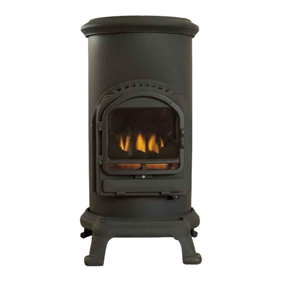
'THURCROFT'
MOBILE GAS STOVE
MODEL NUMBER'S FFSC00MB / MB1 / MB2
USE ONLY IN A WELL VENTILATED
AREA
INSTALLATION, USER AND SERVICING INSTRUCTIONS
THESE INSTRUCTIONS MUST REMAIN WITH THE USER
THIS APPLIANCE HAS BEEN FITTED WITH A SUITABLE REGULATOR AND HOSE. THE REGULATOR
WILL FIT A CYLINDER WITH A 21mm VALVE.
THIS APPLIANCE REQUIRES A 7 kg. CYLINDER OF GAS.
This appliance must not be used in high rise apartments, basements, bathrooms
or bedrooms.
When you first light your stove you may detect a slight odour. This will disappear after a few hours use.
0086
THIS APPLIANCE MEETS THE REQUIREMENTS OF THE EUROPEAN GAS DIRECTIVE
1
Advertisement
Table of Contents

Related Manuals for Flavel THURCROFT FFSC00MB


Summary of Contents for Flavel THURCROFT FFSC00MB
- Page 1 'THURCROFT' MOBILE GAS STOVE MODEL NUMBER’S FFSC00MB / MB1 / MB2 USE ONLY IN A WELL VENTILATED AREA INSTALLATION, USER AND SERVICING INSTRUCTIONS THESE INSTRUCTIONS MUST REMAIN WITH THE USER THIS APPLIANCE HAS BEEN FITTED WITH A SUITABLE REGULATOR AND HOSE. THE REGULATOR WILL FIT A CYLINDER WITH A 21mm VALVE.
-
Page 2: Table Of Contents
Contents Page No. List of components Appliance Data ENERAL EQUIREMENTS Ventilation Preparing the appliance for use SERS UIDE Lighting the stove Moving your stove Cleaning and storage & M ERVICING AINTENANCE Installation & Service Record Important Note These Installation Instructions must be adhered to without exception. -
Page 3: List Of Components
COMPONENTS LIST Before connecting the gas cylinder ensure that all the components listed below are included in the packaging; Mobile Gas Stove Ceramic Coal Matrix APPLIANCE DATA MODEL No. FFSC00MB FFSC00MB1 FFSC00MB2 GAS TYPE G30 or G31 JET SIZE 0.75mm 0.75mm 0.75mm HEAT INPUT (Gross) -
Page 4: Ventilation
removed from the appliance when it is cool and gently brushed clean. This type of soot formation only occurs after a long period of burning at low fire. Ventilation Use only in a well ventilated room. The room in which the heater is to be used must be provided with adequate ventilation at all times to ensure the proper removal of products of combustion and to reduce the possibility of condensation. - Page 5 Fitting the Gas Cylinder Warning: Gas cylinders must not be fitted or changed in the presence of naked flames. Remove the plastic safety cap by rotating it until the arrow points out through the gap in the cylinder shroud, pull on the plastic strap and then lift off the safety cap. Remove the rear access door and place the cylinder close behind the stove.
-
Page 6: Users Guide
VERTICAL / ON HORIZONTAL / OFF Regulator USERS GUIDE Lighting the stove Reach through the aperture in the rear access door and turn on the gas by turning the switch on the regulator upwards. Depress the control knob and turn it fully clockwise. Keep the control knob fully depressed and rotate it fully anticlockwise. -
Page 7: Moving Your Stove
Note; After changing the cylinder more than one attempt may be needed to light the appliance as air may have entered the pilot gas supply and this will take a few attempts to pass through. This may also happen if the stove has not been used for some time and may also cause the pilot to burn with a roaring noise. - Page 8 Basic Service (See Figures 1 and 2, page 9) Note: The oxy pilot must be changed annually as a condition of the guarantee. Remove the glass door panel and the ceramic coal matrix as previously described. Clean any debris and soot from the burner top. This can be done by using a soft brush or a vacuum cleaner.
- Page 9 To Remove the Injector Remove the Burner/ Control assembly as described above. Unscrew the tube nut securing the gas supply pipe to the injector elbow. Unscrew the injector elbow from its carriage. The injector can now be removed from the elbow. To Remove the Control Valve Remove the Burner/ Control assembly as described above.
-
Page 10: Installation & Service Record
Installation & Service Record Please ensure that installer completes the installation record below INSTALLATION RECORD Appliance Supplied by: ..Installation Date: Serial No.: Installed By: ..No.: Signed by Installer:... - Page 11 RECORD OF 1 SERVICE RECORD OF 2 SERVICE Serviced by: No.: ..Serviced by: No.: ..Service Date: Signed: ..Service Date: Signed: ..Comments: Comments: RECORD OF 3 SERVICE RECORD OF 4 SERVICE Serviced by: No.: ..Serviced by: No.: ..
- Page 12 B-123340 Issue 1 BFM Europe Limited Trentham Lakes Stoke on Trent, Staffordshire ST4 4TJ Tel: (01782) 339000 Fax: (01782) 339009 Email: info@bfm-europe.com www.bfm-europe.com...
Need help?
Do you have a question about the THURCROFT FFSC00MB and is the answer not in the manual?
Questions and answers