
Related Manuals for U-Line 3024FZR


Summary of Contents for U-Line 3024FZR
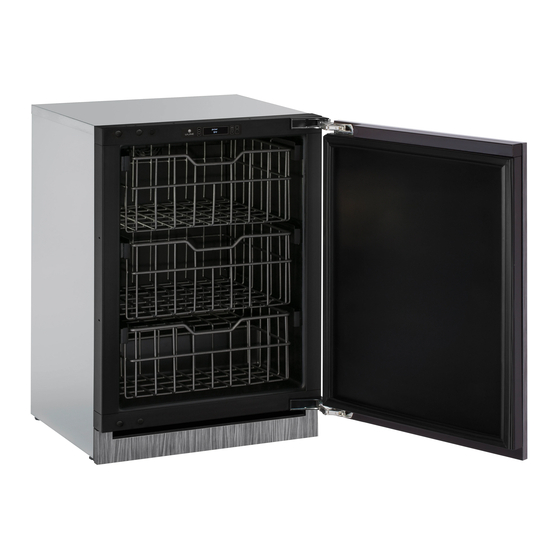
- Page 1 USER GUIDE SAFETY • INSTALLATION & INTEGRATION • OPERATING INSTRUCTIONS • MAINTENANCE • SERVICE RIGHT PRODUCT. RIGHT PLACE. RIGHT TEMPERATURE. SINCE 1962. Modular 3000 Series 3024FZR 24" Freezer • •...
-
Page 2: Table Of Contents
USER GUIDE u-line.com SAFETY • INSTALLATION & INTEGRATION • OPERATING INSTRUCTIONS • MAINTENANCE • SERVICE Contents Intro Troubleshooting Warranty Safety Safety and Warning Disposal and Recycling Installation Environmental Requirements Electrical Cutout Dimensions Product Dimensions Side by Side Installation Anti-Tip Bracket... -
Page 3: U-Line.com
1. U-Line Customer Care must be contacted immediately at +1.800.779.2547. 2. Service or repairs performed on the unit without prior written approval from U-Line is not permitted. If the unit has been altered or repaired in the field without prior written approval from U-Line, claims will not be eligible. -
Page 4: Safety And Warning
USER GUIDE u-line.com SAFETY • INSTALLATION & INTEGRATION • OPERATING INSTRUCTIONS • MAINTENANCE • SERVICE Safety and Warning DANGER NOTICE This unit contains R600a (Isobutane) which is a Please read all instructions before installing, flammable hydrocarbon. It is safe for regular operating, or servicing the appliance. -
Page 5: Disposal And Recycling
USER GUIDE u-line.com SAFETY • INSTALLATION & INTEGRATION • OPERATING INSTRUCTIONS • MAINTENANCE • SERVICE Disposal and Recycling DANGER RISK OF CHILD ENTRAPMENT. Before you throw away your old refrigerator or freezer, take off the doors and leave shelves in place so children may not easily climb inside. -
Page 6: Environmental Requirements
USER GUIDE u-line.com SAFETY • INSTALLATION & INTEGRATION • OPERATING INSTRUCTIONS • MAINTENANCE • SERVICE Environmental Requirements This model is intended for indoor/interior applications only and is not to be used in installations that are open/ exposed to natural elements. - Page 7 USER GUIDE u-line.com SAFETY • INSTALLATION & INTEGRATION • OPERATING INSTRUCTIONS • MAINTENANCE • SERVICE Electrical WARNING SHOCK HAZARD — Electrical Grounding Required. Never attempt to repair or perform maintenance on the unit until the electricity has been disconnected. Never remove the round grounding prong from the plug and never use a two-prong grounding adapter.
-
Page 8: Cutout Dimensions
SAFETY • INSTALLATION & INTEGRATION • OPERATING INSTRUCTIONS • MAINTENANCE • SERVICE Cutout Dimensions CUTOUT DIMENSIONS PREPARE SITE Your U-Line product has been designed exclusively for a built-in installation. When built-in, your unit does not Preferred location require additional air space for top, sides, or rear. -
Page 9: Product Dimensions
USER GUIDE u-line.com SAFETY • INSTALLATION & INTEGRATION • OPERATING INSTRUCTIONS • MAINTENANCE • SERVICE Product Dimensions Not Including Handle 24" (610 mm) 33-11/16" to 34-11/16" (856 to 881 mm) 23-5/8" (600 mm) 3-5/8" to 4-5/8" (92 mm to 118 mm) -
Page 10: Side By Side Installation
USER GUIDE u-line.com SAFETY • INSTALLATION & INTEGRATION • OPERATING INSTRUCTIONS • MAINTENANCE • SERVICE Side-by-Side Installation Hinge-by-Hinge Installation (Mullion) When installing two units hinge-by-hinge, 13/16" (22 mm) OTHER SITE REQUIREMENTS is required for integrated models. Additional space may be Side-by-Side Installation needed for any knobs, pulls or handles installed. -
Page 11: Anti-Tip Bracket
USER GUIDE u-line.com SAFETY • INSTALLATION & INTEGRATION • OPERATING INSTRUCTIONS • MAINTENANCE • SERVICE Anti-Tip Bracket 5. Using a 3/32" drill bit, drill 3 pilot holes 5/8" (16 mm) deep into bottom of countertop. Use the anti-tip bracket as a template. - Page 12 USER GUIDE u-line.com SAFETY • INSTALLATION & INTEGRATION • OPERATING INSTRUCTIONS • MAINTENANCE • SERVICE 5. Using a 3/32" drill bit, drill 3 pilot holes 5/8" (16 mm) deep into cabinetry frame using the anti-tip bracket as a template. 6. Install the 3 remaining #8x5/8" screws into the plate using a #2 Phillips head screwdriver.
-
Page 13: General Installation
USER GUIDE u-line.com SAFETY • INSTALLATION & INTEGRATION • OPERATING INSTRUCTIONS • MAINTENANCE • SERVICE General Installation INSTALLATION 1. Plug in the power/electrical cord. LEVELING INFORMATION 1. Use a level to confirm 2. Gently push the unit into position. Be careful not to the unit is level. -
Page 14: Integrated Grille / Plinth Dimensions
3. Apply double sided tape to the backside of the integrated grill (plinth strip/base fascia). Use the diagram below for reference. U-Line recommends ™ ™ tape, a high strength bonding tape. -
Page 15: Grille / Plinth Installation
USER GUIDE u-line.com SAFETY • INSTALLATION & INTEGRATION • OPERATING INSTRUCTIONS • MAINTENANCE • SERVICE Grille - Plinth Installation Installing the grille (plinth strip/base fascia) REMOVING AND INSTALLING GRILLE 1. Align slots in grille (plinth strip/base fascia) rail with (PLINTH STRIP/BASE FASCIA) -
Page 16: Door Swing
USER GUIDE u-line.com SAFETY • INSTALLATION & INTEGRATION • OPERATING INSTRUCTIONS • MAINTENANCE • SERVICE Door Swing Wall For Integrated models that are installed adjacent to a wall, 1/4" (6 mm) 1/4" (6 mm) clearance is recommended from wall on hinge side to allow the door to open 90°. -
Page 17: Door Stop
3. Once cover is removed, slide hinge pin into hole as shown. Pin should slide into place, stopping the door at Your U-Line unit was shipped to you with the optional 90° 90°; if the pin does not go into the hole shown, hold pin. -
Page 18: Door Adjust
USER GUIDE u-line.com SAFETY • INSTALLATION & INTEGRATION • OPERATING INSTRUCTIONS • MAINTENANCE • SERVICE Door Adjustments 4. The wrap hinges on top of the door. Carefully pull wrap away and then up. See below. DOOR ALIGNMENT AND ADJUSTMENT Align and adjust the door if it is not level or is not sealing properly. - Page 19 USER GUIDE u-line.com SAFETY • INSTALLATION & INTEGRATION • OPERATING INSTRUCTIONS • MAINTENANCE • SERVICE Alignment and Adjustment Procedure 1. Using a T-25 Torx Bit, loosen each pair of Torx head screws on both the upper and lower hinge plates.
-
Page 20: First Use
USER GUIDE u-line.com SAFETY • INSTALLATION & INTEGRATION • OPERATING INSTRUCTIONS • MAINTENANCE • SERVICE First Use All U-Line controls are preset at the factory. Initial startup requires no adjustments. NOTICE U-Line recommends allowing the unit to run overnight before loading with product. -
Page 21: Control Operation
USER GUIDE u-line.com SAFETY • INSTALLATION & INTEGRATION • OPERATING INSTRUCTIONS • MAINTENANCE • SERVICE Control Operation Zone Toggle Select Polar O°F Can be displayed in Celsius Power Down U-Select Lighting CONTROL FUNCTION GUIDE FUNCTION COMMAND DISPLAY/OPTIONS Press and hold Display will count down from 5 to off. -
Page 22: Interior Lighting
Interior Lighting (L) (R) Temp Left or right zone Verify door is closed and Your U-Line 3000 Series unit uses a state of the art LED Hi 6H+ temperature +10° over sealing. Contact Customer set point for over 6 Care if persistent. - Page 23 SAFETY • INSTALLATION & INTEGRATION • OPERATING INSTRUCTIONS • MAINTENANCE • SERVICE CUSTOMER MENU 2. Press to scroll through available information. The 3000 Series of U-Line undercounter refrigeration appliances contains a feature rich customer menu. The 3. To return to the Customer Menu, press and select Customer Menu allows access to a series of advanced “Return to Menu”.
- Page 24 RETURN TO MENU LANGUAGES ENGLISH 4. Press to confirm your choice. Down The U-Line 3000 Series of models supports a number of Fahrenheit/Celsius display languages including English, Spanish, French and German. Select RETURN TO MENU 1. To change display language select Languages from the FARENHEIT/CELSIUS DEGREES = °F...
- Page 25 The Help screen displays the following: To access Factory Default: • Model. 1. Press to select “Factory Default”. • U-Line contact information. • Software version. 2. Press • Serial Number. To restore settings to their factory default: To exit the Help menu, press to select “Return to...
-
Page 26: Sabbath Mode
USER GUIDE u-line.com SAFETY • INSTALLATION & INTEGRATION • OPERATING INSTRUCTIONS • MAINTENANCE • SERVICE 7. Press to change “Off” to “On”. Sabbath Mode 8. Press to confirm your selection. The Display will fade out as the unit enters Sabbath Mode. -
Page 27: Airflow And Product Loading
USER GUIDE u-line.com SAFETY • INSTALLATION & INTEGRATION • OPERATING INSTRUCTIONS • MAINTENANCE • SERVICE Airflow and Product Loading NOTICE The unit requires proper airflow to perform at its highest efficiency. Do not block the front grille, internal fans or vents at any time, or the unit will not perform as expected. -
Page 28: Maintenance
® monthly. For best results use Claire Stainless Steel Polish and Cleaner, which can be purchased from U-Line Rinse the interior using a soft sponge and clean water. Corporation (Part Number 173348). Comparable products are acceptable. Frequent cleaning will remove surface contamination that could lead to rust. - Page 29 USER GUIDE u-line.com SAFETY • INSTALLATION & INTEGRATION • OPERATING INSTRUCTIONS • • SERVICE MAINTENANCE NOTICE The drain pan was not designed to capture the water created when manually defrosting. To prevent water from overflowing the drain pan and possibly damaging water sensitive flooring, the unit must be removed from cabinetry.
-
Page 30: Cleaning Condenser
USER GUIDE u-line.com SAFETY • INSTALLATION & INTEGRATION • OPERATING INSTRUCTIONS • MAINTENANCE • SERVICE Cleaning Condenser INTERVAL - EVERY SIX MONTHS To maintain operational efficiency, keep the front grille (plinth strip/base fascia) free of dust and lint, and clean the condenser when necessary. -
Page 31: Troubleshooting
• Evaporator: Refrigerant flowing through an evaporator may sound like boiling liquid. BEFORE CALLING FOR SERVICE If you think your U-Line product is malfunctioning, read • Condenser Fan: Air moving through a condenser may the CONTROL OPERATION section to clearly understand be heard. - Page 32 USER GUIDE u-line.com SAFETY • INSTALLATION & INTEGRATION • OPERATING INSTRUCTIONS • MAINTENANCE • SERVICE Causes which affect the internal temperatures of Problem Possible Cause and Remedy the cabinet include: Product Is Not Air temperature does not indicate product • Temperature setting.
- Page 33 God, such as fire, floods, wind, and U-Line product to be free from defects in materials and lightning; damages incurred or resulting from shipping, workmanship for a period of five years from the date of improper installation, unauthorized modification, or purchase.
- Page 34 7. If a product defect is discovered during the applicable warranty period, you must promptly notify either U-Line at 8900 N. 55th Street, Milwaukee, Wisconsin 53223 USA or at +1.800.779.2547 or the dealer from whom you purchased the product. In no event shall such notification be received later than 30 days after the expiration of the applicable warranty period.