
Related Manuals for Acer Aspire 4745


Summary of Contents for Acer Aspire 4745
- Page 1 Acer Aspire 4745 Service Guide Service guide files and updates are available on the ACER/CSD web; for more information, please refer to http://csd.acer.com.tw PRINTED IN TAIWAN...
-
Page 2: Revision History
Revision History Please refer to the table below for the updates made on this service guides. Date Chapter Updates... - Page 3 Copyright Copyright © 2010 by Acer Incorporated. All rights reserved. No part of this publication may be reproduced, transmitted, transcribed, stored in a retrieval system, or translated into any language or computer language, in any form or by any means, electronic, mechanical, magnetic, optical, chemical, manual or otherwise, without the prior written permission of Acer Incorporated.
-
Page 4: Conventions
Conventions The following conventions are used in this manual: SCREEN MESSAGES NOTE WARNING CAUTION IMPORTANT NOTE: This symbol where placed in the Service Guide designates a component that should be recycled according to the local regulations. Denotes actual messages that appear on screen. - Page 5 DIFFERENT part number code to those given in the FRU list of this printed Service Guide. You MUST use the list provided by your regional Acer office to order FRU parts for repair and service of customer machines.
-
Page 7: Table Of Contents
Your Acer Notebook tour ........ - Page 8 Table of Contents Removing the LCD Module .........64 Removing the Mainboard .
- Page 9 Acer Aspire 4745 Exploded Diagrams ........132...
- Page 10 Table of Contents...
-
Page 11: System Specifications
• Up to 16 GB using four soDIMM modules for i7 models • Display 14" HD 1366 x 768 pixel resolution, high-brightness (200-nit) Acer CineCrystal™ LED-backlit TFT • LCD, supporting simultaneous multi-window viewing via Acer GridVista™ 16:9 aspect ratio •... -
Page 12: Optical Drive
16.7 million colors • External resolution / refresh rates6: • VGA port up to 2048 x 1536: 85 Hz • HDMI™ port up to 1920 x 1080 60 Hz • MPEG-2/DVD decoding • VC-1 and H.264 (AVC) decoding • Microsoft® DirectX® Video Acceleration (DXVA) application interface (API) •... - Page 13 Write: 24X CD-R, 16X CD-RW, 8X DVD-R, 8X DVD+R, 4X DVD-R DL, 4X DVD+R DL, 6X • DVD-RW, 8X DVD+RW, 5X DVD-RAM Communication Acer video conferencing solution1, featuring: • Acer Crystal Eye high-definition webcam with 1280 x 1024 resolution • WLAN: • Acer InviLink™ Nplify™ 802.11 b/g/n Wi-Fi CERTIFIED™ •...
- Page 14 Multi-gesture touchpad pointing device supporting scroll, pinch, rotate, flip • 10 function keys, four cursor keys, two Windows® keys, hotkey controls, independent standard • numeric keypad, international language support Acer Programming key • Easy-launch keys: Communication® • Media control keys (printed on keyboard): play/pause, stop, previous, next •...
- Page 15 Acer Arcade™ Deluxe· • NTI Media Maker™ • Gaming· • Oberon GameZone Acer Edition1 · • WildTangent® Acer Edition1 • Communication and ISP· • Microsoft® Silverlight™· • Windows Live™ Essentials - Wave 3.2 (Mail, Photo Gallery, Live™ Messenger, Movie Maker, •...
-
Page 16: System Block Diagram
System Block Diagram CLOCK GENERATOR DDR III SO-DIMM 0 SO-DIMM 1 HDD (SATA) ODD (SATA) USB board USB Port X3 USB Port x 1 Bluetooth CardReader AU6437 Audio CODEC RTL ALC271X SPDIF/HP INT MIC intel <MCH Processor> Arrandale (SG) Dual Channel 800/ 1066 MHz rPGA 989 (37.5mm X 37.5mm) -
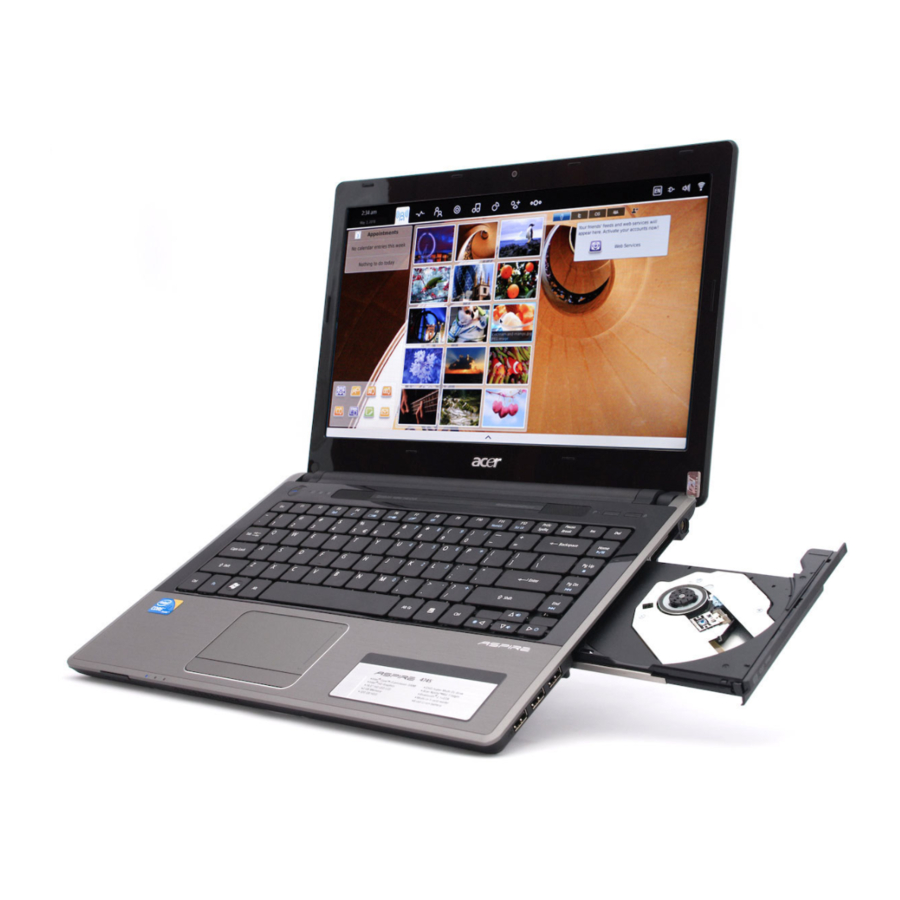
Page 17: Your Acer Notebook Tour
Your Acer Notebook tour Front View Icon Chapter 1 Item Acer Crystal Eye Web camera for video communication webcam (for selected models). Microphone Internal microphone for recording sound. Display screen Also called Liquid-Crystal Display (LCD), displays computer output. Description... - Page 18 Icon Item Indicates when the hard disk drive is active. Num Lock Lights up when Num Lock is activated. indicator Caps Lock Lights up when Caps Lock is activated. indicator Power button Turns the computer on and off. Keyboard For entering data into your computer. TouchPad Touch-sensitive pointing device which functions like a computer mouse.
-
Page 19: Closed Front View
Closed Front View Icon Left View Icon Chapter 1 Item Multi-in-1 Accepts Secure Digital (SD), card reader MultiMediaCard (MMC), Memory Stick (MS), Memory Stick PRO (MS PRO), xD-Picture Card (xD). Note: Push to remove/install the card. Only one card can operate at any given time. Item Kensington lock Connects to a Kensington-compatible... -
Page 20: Right View
Icon Right View Icon USB 2.0 ports Optical drive Optical disk access indicator Emergency eject hole DC-in jack Item Microphone-in Accepts input from external microphones. jack Headphones/ Connects to audio line-out devices speaker/line-out (e.g. speakers, headphones). jack Item Connect to USB 2.0 devices (e.g. USB mouse, USB camera). -
Page 21: Bottom View
Bottom View Icon Indicators The computer has several easy-to-read status indicators. Icon Power Chapter 1 Item Battery bay Houses the computer's battery pack. Battery lock Locks the battery in position. Hard disk bay Houses the computer's hard disk (secured with screws). Memory Houses the computer's main memory. - Page 22 Icon Battery Communication indicator Function Indicates the computer's battery status. NOTE: 1. Charging: The light shows amber when the battery is charging. 2. Fully charged: The light shows green when in AC mode. Indicates when the hard disk drive is active. Indicates the computer’s wireless connectivity device status.
-
Page 23: Touchpad Basics
TouchPad Basics The following items show you how to use the TouchPad: • Move your finger across the TouchPad (1) to move the cursor. • Press the left (2) and right (3) buttons located beneath the TouchPad to perform selection and execution functions. -
Page 24: Using The Keyboard
Using the Keyboard The keyboard has full-sized keys and an embedded numeric keypad, separate cursor, lock, Windows, function and special keys. Lock Keys and embedded numeric keypad The keyboard has two lock keys which you can toggle on and off. Lock key Caps Lock When Caps Lock is on, all alphabetic characters typed are in uppercase. -
Page 25: Windows Keys
Windows Keys The keyboard has two keys that perform Windows-specific functions. Windows key Pressed alone, this key has the same effect as clicking on the Windows Start button; it launches the Start menu. It can also be used with other keys to provide a variety of functions: <... -
Page 26: Hot Keys
Hot Keys The computer employs hotkeys or key combinations to access most of the computer’s controls like screen brightness, volume output and the BIOS utility. To activate hot keys, press and hold the <Fn> key before pressing the other key in the hotkey combination. Hotkey Icon <Fn>... -
Page 27: Hardware Specifications And Configurations
4 MB PGA988P Fan Speed (rpm) 2500 3100 3500 3900 4200 Fan Speed (rpm) 2500 3100 3500 3900 4200 Insyde BIOS 1.00 Flash Core Acer P/N Voltage KC.33001.DMP KC.35001.DMP KC.43001.DMP KC.52001.DMP KC.54001.DMP KC.62001.DMP SPL Spec (dBA) SPL Spec (dBA) Specification... - Page 28 • Suspend to RAM (S3)/Disk (S4) • Various hot-keys for system control • Support SMBIOS 2.3, PCI2.2. • Refer to Acer BIOS specification. • DMI utility for BIOS serial number configurable/asset tag • Support PXE • Support Y2K solution •...
- Page 29 Wireless Module Item Manufacturer Specifications LAN Module Item Chipset Specifications Bluetooth Item Chipset Features Specifications Chapter 1 Specification Intel® WiFi Link 1000 • IEEE 802.11b/g and Draft-N1 compliant • Advanced security via 802.11i • Industry-leading power consumption • Includes Wi-Fi PAN – Intel® My WiFi Technology •...
- Page 30 Hard Disk Drive Interface Item Vendor & Model Seagate Name Capacity (MB) 160, 250, 320, Bytes per sector Data heads Drive Format Disks Spindle speed (RPM) Performance Specifications Buffer size Interface DC Power Requirements Voltage 5V ±5% tolerance Super-Multi Drive Module Item Vendor &...
- Page 31 Item Applicable disc DVD-ROM: formats 4.7GB (Single Layer) 8.5GB (Dual Layer) DVD-R: 3.95GB (Ver. 1.0: read only) 4.7GB (Ver. 2.0 for Authoring: read only) 4.7GB (Ver. 2.1 for General: read & write) (DL) 8.5GB (Ver. 3.0) DVD-RW: 4.7GB (Ver. 1.2/ Rev 1.0, 2.0, 3.0) DVD-RAM: 1.46GB/side, 4.7GB/side (Ver.
- Page 32 Power and Keyboard Controller Item Controller Total number of keypads Windows logo key Hotkeys Battery Item Vendor & model name Battery Type Pack capacity Normal Voltage Package configuration Item Vendor/model name Screen Diagonal (in) Display resolution (pixels) Pixel Pitch Display Mode Typical White Luminance (cd/m (also called Brightness) Contrast Ratio...
-
Page 33: System Utilities
System Utilities BIOS Setup Utility The BIOS Setup Utility is a hardware configuration program built into your computer’s BIOS (Basic Input/ Output System). Your computer is already properly configured and optimized, and you do not need to run this utility. However, if you encounter configuration problems, you may need to run Setup. -
Page 34: Aspire 4745 Bios
Aspire 4745 BIOS Information The Information screen displays a summary of your computer hardware information. Information Main Security C P U T y p e C P U T y p e C P U S p e e d... -
Page 35: Main
Main The Main screen allows the user to set the system time and date as well as enable and disable boot option and recovery. Information Main S y s t e m Ti m e : S y s t e m Ti m e : S y s t e m D a t e : S y s t e m D a t e : To t a l M e m o r y :... -
Page 36: Security
Security The Security screen contains parameters that help safeguard and protect your computer from unauthorized use. Information The table below describes the parameters in this screen. Settings in boldface are the default and suggested parameter settings. Parameter Supervisor Password Is User Password Is HDD Password Is Set Supervisor Password... -
Page 37: Setting A Password
Setting a Password Follow these steps as you set the user or the supervisor password: Use the ↑ and ↓ keys to highlight the Set Supervisor Password parameter and press the Enter key. The Set Supervisor Password box appears: Type a password in the “Enter New Password” field. The password length can not exceed 8 alphanumeric characters (A-Z, a-z, 0-9, not case sensitive). - Page 38 Changing a Password Use the ↑ and ↓ keys to highlight the Set Supervisor Password parameter and press the Enter key. The Set Password box appears. Type the current password in the Enter Current Password field and press Enter. Type a password in the Enter New Password field. Retype the password in the Confirm New Password field.
-
Page 39: Boot
Boot This menu allows the user to decide the order of boot devices to load the operating system. Bootable devices includes the USB diskette drives, the onboard hard disk drive and the DVD drive in the module bay. Select Boot Devices to select specific devices to support boot. Information Main B o o t p r i o r i t y o r d e r :... -
Page 40: Exit
Exit The Exit screen allows you to save or discard any changes you made and quit the BIOS Utility. Information Main E x i t S a v i n g C h a n g e s E x i t S a v i n g C h a n g e s E x i t D i s c a r d i n g C h a n g e s E x i t D i s c a r d i n g C h a n g e s L o a d S e t u p D e f a u l t s... -
Page 41: Bios Flash Utilities
BIOS Flash Utilities The BIOS flash memory update is required for the following conditions: • New versions of system programs • New features or options • Restore a BIOS when it becomes corrupted. Use the Flash utility to update the system BIOS flash ROM. NOTE: If you do not have a crisis recovery diskette at hand, then you should create a Crisis Recovery Diskette before you use the Flash utility. -
Page 42: Dos Flash Utility
DOS Flash Utility Perform the following steps to use the DOS Flash Utility: Press F2 during boot to enter the Setup Menu. Select Boot Menu to modify the boot priority order, for example, if using USB HDD to Update BIOS, move USB HDD to position 1. - Page 43 In flash BIOS, the message Please do not remove AC Power Source displays. NOTE: If the AC power is not connected, the following message displays. Plug in the AC power to continue. Flash is complete when the message Flash programming complete displays. Chapter 2...
-
Page 44: Winflash Utility
WinFlash Utility Perform the following steps to use the WinFlash Utility: Double-click the WinFlash executable. Click OK to begin the update. A progress screen displays. Chapter 2... -
Page 45: Remove Hdd/Bios Password Utilities
Remove HDD/BIOS Password Utilities This section provides you with details about removing HDD/BIOS password: Remove HDD Password: If you key in the wrong HDD password three times, an error is generated. To reset the HDD password, perform the following steps: On another computer, run HDD_PW.exe. - Page 46 Removing BIOS Passwords: To clear the User or Supervisor passwords, open the DIMM door and use a metal instrument to short the G1 and G2 points. Cleaning BIOS Passwords To clean the User or Supervisor passwords, perform the following steps: From a DOS prompt, execute clnpwd.exe Press 1 or 2 to clean the desired password shown on the screen.
- Page 47 Using Boot Sequence Selector The Boot Sequence Selector allows the boot order to be changed without accessing the BIOS. To use Boot Sequence Selector, perform the following steps: Enter into DOS. Execute BS.exe to display the usage screen. Select the desired boot sequence by entering the corresponding sequence. For example, enter BS2 to change the boot sequence to HDD | CD ROM | LAN | Floppy.
- Page 48 The following examples show the commands and the corresponding output information. Read DMI Information from Memory Input: dmitools /r Output: Manufacturer (Type1, Offset04h): Acer Product Name (Type1, Offset05h): TravelMate xxxxx Serial Number (Type1, Offset07h): 01234567890123456789 UUID String (Type1, Offset08h): xxxxxxxx-xxxx-xxxx-xxxx-xxxxxxxxxxxx Asset Tag (Type3, Offset04h): Acet Asstag...
- Page 49 Using the LAN MAC EEPROM Utility You can use the MAC.BAT utility to write the MAC.CFG file to the EEPROM in DOS mode. Use a text editor to open the MAC.CFG file. You can see the MAC.CFG contents as shown: WriteData = ‘001122334455' StartAddr=7A WriteLeng=6...
- Page 50 Chapter 2...
-
Page 51: Machine Disassembly And Replacement
Machine Disassembly and Replacement IMPORTANT:The outside housing and color may vary from the mass produced model. This chapter contains step-by-step procedures on how to disassemble the notebook computer for maintenance and troubleshooting. Disassembly Requirements To disassemble the computer, you need the following tools: Wrist grounding strap and conductive mat for preventing electrostatic discharge •... -
Page 52: General Information
General Information Pre-disassembly Instructions Before proceeding with the disassembly procedure, make sure that you do the following: 1. Turn off the power to the system and all peripherals. 2. Unplug the AC adapter and all power and signal cables from the system. 3. -
Page 53: External Module Disassembly Process
External Module Disassembly Process IMPORTANT:The outside housing and color may vary from the mass produced model. External Modules Disassembly Flowchart The flowchart below gives you a graphic representation on the entire disassembly sequence and instructs you on the components that need to be removed during servicing. For example, if you want to remove the main board, you must first remove the keyboard, then disassemble the inside assembly frame in that order. -
Page 54: Removing The Battery Pack
Removing the Battery Pack 1. Turn computer over. Slide the battery lock in the direction shown. 2. Slide and hold the battery release latch to the release position (1), then lift out the battery pack from the main unit (2). Please detach the battery and follow local regulations for disposal. -
Page 55: Removing The Sd Dummy Card
Removing the SD dummy card 1. Push the SD dummy card all the way in to eject it. 2. Pull it out from the slot. Chapter 3... -
Page 56: Removing The Lower Cover
Removing the Lower Cover 1. See “Removing the Battery Pack” on page 44. 2. Loosen the five (5) captive screws from the lower cover. 3. Remove the lower cover as shown. Chapter 3... -
Page 57: Removing The Optical Drive Module
Removing the Optical Drive Module 1. See “Removing the Lower Cover” on page 46. 2. Remove the screw securing the ODD module. Step ODD Module M2.5*4L 3. Using your fingers, pull the optical drive module out from the chassis. 4. Remove the two screws securing the ODD bracket and remove the ODD bracket from the optical disk drive module. - Page 58 Step Size Quantity Screw Type ODD Bracket M2.0*3L 5. Remove the ODD bezel by rotating the top edge downward and pulling it clear of the module. Chapter 3...
-
Page 59: Removing The Dimm Modules
Removing the DIMM Modules 1. See “Removing the Lower Cover” on page 46. 2. Push out the release latches on both sides of the DIMM socket to release the DIMM module. 3. Remove the DIMM module. 4. Repeat steps for the second DIMM module if present. Chapter 3... -
Page 60: Removing The Wlan Module
Removing the WLAN Module 1. See “Removing the Lower Cover” on page 46. 2. Disconnect the two (2) antenna cables from the WLAN Board and remove the one (1) screw to release the WLAN Board. NOTE: Cable placement is Black to the TR1 terminal (left) and White to the TR2 terminal (right). Step WLAN Board M2.0*3... -
Page 61: Removing The Hard Disk Drive Module
Removing the Hard Disk Drive Module 1. See “Removing the Lower Cover” on page 46. 2. Using the pull-tab, slide the HDD Module in the direction of the arrow to disconnect the interface. 3. Lift the HDD Module clear of the HDD bay. 4. -
Page 62: Main Unit Disassembly Process
Main Unit Disassembly Process Main Unit Disassembly Flowchart Remove Bluetooth Remove USB Board Module Remove CRT Cable Remove LCD module Remove Right Speaker Module Remove DC cable Screw List Step LCD Module M2.5*4 M2.0*3 M2.5*3 Upper Cover M2.5*4L M2.0*3L L. Speaker Module M2.5*4L L. -
Page 63: Removing The Keyboard
Removing the Keyboard CAUTION: Using tools to remove the Keyboard may cause damage to the outer casing. It is recommended that you only use your fingers to remove the Keyboard. 1. See “Removing the Battery Pack” on page 44. 2. Remove the 14 securing screws from the lower cover. Step Keyboard M2.5*6.5... - Page 64 4. Release each clip, working from one side to the other. 5. Using both hands, gently pry up the cover as shown and turn it over. 6. Open the locking latch on the FFC, and disconnect the cable as shown. 7.
-
Page 65: Removing The Upper Cover
Removing the Upper Cover 1. See “Removing the Keyboard” on page 53. 2. Turn the computer over. Disconnect the following four cables from the Mainboard: Left speaker cable Touchpad FFC Power Switch FFC Function Board FFC Chapter 3... - Page 66 3. Disconnect A as shown. 5. Release the locking latch and remove C as shown. NOTE: Avoid pulling on cables directly to prevent damage to the connectors. Use the pull-tabs on FFC cables whenever available. 4. Release the locking latch and remove B as shown. 6.
- Page 67 7. Remove the eight (8) screws from the top cover. Step Upper Cover M2.5*3L (red callout) Upper Cover M2.5*4L (blue callout) 8. Remove the Upper Cover by lifting directly upward from the front as shown. Chapter 3 Size Quantity Screw Type...
-
Page 68: Removing The Power Switch Board
Removing the Power Switch Board 1. See “Removing the Upper Cover” on page 55. 2. Locate the Power Switch Board in the Upper Cover. 3. Release the securing latch holding the Power Switch Board FFC and remove. 4. Remove the two (2) screws and lift the Power Switch Board clear of the Upper Cover. Step Power Switch M2.0*3widehead... -
Page 69: Removing The Function Board
Removing the Function Board 1. See “Removing the Upper Cover” on page 55. 2. Locate the Function Board in the Upper Cover and remove the two (2) screws attaching it to the upper cover. Step Function Board M2.0*3widehead 3. Lift the Function Board clear of the Upper Cover. 4. -
Page 70: Removing The Left Speaker Module
Removing the Left Speaker Module 1. See “Removing the Upper Cover” on page 55. 2. Remove the speaker cable from it’s guides. 3. Remove the adhesive foil tab covering the speaker cable and remove the one (1) securing screws from the Speaker Module. -
Page 71: Removing The Usb Board
Removing the USB Board 1. See See “Removing the Upper Cover” on page 55. 2. Remove the single securing screw from the USB Board. Step USB Board M2.5*4L 3. Release the FFC latch and remove the FFC cable from the mainboard connector. 4. - Page 72 5. Lift the USB Board upward away from the chassis. Chapter 3...
-
Page 73: Removing The Bluetooth Module
Removing the Bluetooth Module 1. See “Removing the Upper Cover” on page 55. 2. Remove the single securing screw from the Bluetooth board. Step Bluetooth Board M2.3*3L 3. Disconnect the cable from the Mainboard and lift the Bluetooth Module off the mainboard. Chapter 3 Size Quantity... -
Page 74: Removing The Lcd Module
4. Disconnect the cable from the Bluetooth Module. Removing the LCD Module 1. See “Removing the Bluetooth Module” on page 63. 2. Remove the adhesive holding the LCD cable. 3. Push snaps to release the cable from the mainboard. 4. Remove LCD cable from fan module. Chapter 3... -
Page 75: Removing The Mainboard
5. Remove the four securing screws (two each side) from the LCD module. Step LCD Module M2.5*6.5 6. Ensure that all cables entering the LCD are free of the chassis and remove the LCD module from the chassis. Removing the Mainboard 1. - Page 76 3. Disconnect the right speaker cable. 4. Unlock the microphone cable release it from the clasps on the cooling fan. Chapter 3...
- Page 77 5. Turn the computer over and remove the DC-In cable. 6. Remove the one (1) securing screw from the Mainboard. Step Size Quantity Screw Type Mainboard M2.5*4L Chapter 3...
-
Page 78: Removing The Thermal Module
7. Lift the Mainboard right side first and remove it from the Lower Cover. Please detach the mainboard and follow local regulations for disposal. Removing the Thermal Module 1. See “Removing the Mainboard” on page 65. 2. Turn the Mainboard over and disconnect the Fan cable as shown. 3. -
Page 79: Removing The Cpu
4. Using both hands, lift the Thermal Module clear of the Mainboard. Removing the CPU 1. See “Removing the Thermal Module” on page 68. 2. Using a phillips screw driver, rotate the CPU locking screw 180° counter-clockwise as shown. 3. Lift the CPU clear of the socket as shown. IMPORTANT:The pins on the underside of the CPU are very delicate. -
Page 80: Removing The Rtc Battery
Removing the RTC Battery 1. See “Removing the Mainboard” on page 65. 2. Pry the RTC battery from the mainboard. Please detach the RTC battery and follow local regulations for disposal. Removing the WiFi Antenna Cable 1. See “Removing the Mainboard” on page 65. 2. -
Page 81: Removing The Right Speaker
Removing the Right Speaker 1. See See “Removing the Mainboard” on page 65. 2. Disengage the Right speaker cable from the chassis as shown. 3. Remove the two (2) screws holding the right speaker in place. Step Right Speaker 2.0*3widehead Module 4. -
Page 82: Removing The Dc-In Cable
Removing the DC-In Cable 1. See “Removing the LCD Module” on page 64. 2. Remove one(1) screw from the right hinge bracket. Step DC-In Cable M2.5*4 3. Remove the right hinge bracket. 4. Lift the DC-In jack from the chassis. Size Quantity Screw Type... -
Page 83: Lcd Module Disassembly Process
LCD Module Disassembly Process LCD Module Disassembly Flowchart Remove FPC cable Screw List Step Screw LCD Bezel M2.5*4 LCD Panel M2.0*3 LCD Brackets M2.5*3 Chapter 3 Remove LCD panel from main unit before preceeding Remove LCD bezel Remove camera module Remove LCD panel Remove WLAN Remove microphone... -
Page 84: Removing The Lcd Bezel
Removing the LCD Bezel 1. See “Removing the LCD Module” on page 64. 2. Remove the two lower bezel screw caps and screws. Step LCD Bezel M2.5*4 3. Starting from the top-left corner of the bezel, pry the bezel upwards and away from the panel. Move along the top and left until all sides of the bezel are removed. -
Page 85: Removing The Camera Module
4. Lift the Bezel clear of the LCD Module. Removing the Camera Module 1. See “Removing the LCD Bezel” on page 74. 2. Remove the Camera from the module. 3. Disconnect the camera cable. Chapter 3... -
Page 86: Removing The Lcd Panel
Removing the LCD Panel 1. See “Removing the Camera Module” on page 75. 2. Disengage the various cables from the hinges. 3. Remove the four (4) securing screws from the LCD Panel. Step LCD Panel M2.3*3 4. Lift the LCD Panel clear of the module as shown. Size Quantity Screw Type... -
Page 87: Removing The Fpc Cable
Removing the FPC Cable 1. See “Removing the LCD Panel” on page 76. 2. Turn the LCD panel over to expose the rear. Disengage the adhesive strip securing it in place. 3. Lift the adhesive protector and disconnect the cable from the LCD Panel. 4. -
Page 88: Removing The Microphone Module
Removing the Microphone Module 1. See “Removing the LCD Panel” on page 76. 2. Disengage the cable from the cable guides. 3. Lift the Microphone Module clear of the cover. Removing the Hinges 1. See “Removing the LCD Panel” on page 76. 2. -
Page 89: Removing The Antennas
Removing the Antennas 1. See “Removing the LCD Panel” on page 76. 2. Disengage the left antenna cable from the guides. 3. Remove the adhesive tape and lift the left side antenna from the LCD module as shown. 4. Disengage the right antenna cable from the guides. Chapter 3... - Page 90 5. Remove the adhesive tape and lift the right side antenna from the LCD module as shown. Chapter 3...
-
Page 91: Lcd Module Reassembly Procedure
LCD Module Reassembly Procedure Replacing the MIC and WiFi Antennas 1. Place the Microphone Module in the LCD Module as shown. 3. Replace the left and right antennas as shown. Press down on the adhesive pads to secure the antennas in place. -
Page 92: Replacing The Microphone Module
6. Ensure the antenna cables pass through the hinge well as shown. Replacing the Microphone Module 1. Replace the Microphone Module into the top cover. 2. Replace the cable into the cable guides as shown. Chapter 3... -
Page 93: Replacing The Fpc Cable
Replacing the FPC Cable 1. Attach the FPC cable to the LCD panel and attach the adhesive protector. Replacing the LCD Panel 2. Place the LCD Panel into the module as shown. 3. Replace the six (6) securing screws from the LCD Panel. Chapter 3... -
Page 94: Replacing The Webcam
Replacing the Webcam 1. Connect the cable to the camera module. 2. Place the camera in the LCD Module. Chapter 3... -
Page 95: Replacing The Lcd Bezel
Replacing the LCD Bezel 1. Locate the bezel bottom edge first and press down until there are no gaps between the bezel and the LCD Module. IMPORTANT: Ensure that the LCD cables pass through the hinge wells and are not trapped by the bezel. 2. - Page 96 3. Replace the two screws and screw caps as shown. Chapter 3...
-
Page 97: Main Module Reassembly Procedure
Main Module Reassembly Procedure Replacing the DC-In Cable 1. Place the DC-In jack back into the chassis. 2. Replace the right hinge bracket. 3. Replace the one(1) screw to the right hinge bracket as shown. Chapter 3... -
Page 98: Replacing The Lcd Module
Replacing the LCD Module 1. Replace the LCD module onto the chassis. 2. Replace the four securing screws (two each side) to the LCD module. Replacing the Right Speaker 1. Place the right speaker in to the chassis. Chapter 3... -
Page 99: Replacing The Rtc Battery
2. Replace the two (2) screws to secure the right speaker in place. 3. Replace the right speaker cable in to the chassis as shown. Replacing the RTC Battery 1. Snap the RTC battery into it’s socket as shown. Chapter 3... -
Page 100: Replacing The Cpu
Replacing the CPU IMPORTANT:The CPU has a Pin1 locator that must be positioned corresponding to the marker on the CPU socket. 1. Place the CPU into the CPU socket as shown, taking note of the Pin1 locator. 2. Using a flat-bladed screw driver, rotate the CPU locking screw 180° clockwise to secure the CPU in place. Replacing the Thermal Module IMPORTANT:Apply a suitable thermal grease and ensure all heat pads are in place before replacing the Thermal Module. -
Page 101: Replacing The Mainboard
3. Align the screw holes on the Thermal Module and Mainboard then replace the module. Keep the module as level as possible to spread the thermal grease evenly. 5. Connect the fan cable to the Mainboard. Replacing the Mainboard 1. Place the Mainboard in the chassis, left edge first (1), then rotate it downward into position (2). - Page 102 3. Turn the computer over and replace the DC-In cable. 5. Reattach the microphone cable. 7. Snap the FPC cable into place. 4. Turn the computer over. Feed the mircophone cable through the guides on the fan. 6. Starting at the top, slide your finger down to reattach the adhesive.
- Page 103 9. Connect the right speaker cable. Chapter 3...
-
Page 104: Replacing The Bluetooth Module
Replacing the Bluetooth Module NOTE: The Bluetooth Module and USB Board can be replaced independently and in any order. 1. Connect the smaller end of the Bluetooth cable to 2. Secure the Bluetooth cable in place using the the Bluetooth Module as shown. provided (1) screw. -
Page 105: Replacing The Usb Board
Replacing the USB Board 1. Replace the USB Board in the Lower Cover. 3. Replace the single securing screw. Replacing the TouchPad Bracket 1. Replace the TouchPad FFC, close the locking latch on the connector and replace the adhesive tape. Chapter 3 2. -
Page 106: Replacing The Left Speaker Module
3. Replace the two securing screws. Replacing the Left Speaker Module 1. Place the Speaker Module on the Upper Cover as shown. 3. Lay the speaker cable into it’s guides. 2. Replace the one (1) securing screw. Chapter 3... -
Page 107: Replacing The Function Board
Replacing the Function Board 1. Replace the Function Board FFC and lock it into place. Replacing the Power Switch Board 1. Place the Power Switch Board in to the Upper Cover as shown and replace the two (2) screws. Chapter 3 2. -
Page 108: Replacing The Upper Cover
Replacing the Upper Cover 1. Place the Upper Cover on the Lower Cover back edge first. 3. Continue pressing around the edges of the casing until there are no gaps between the Upper and Lower Covers. 2. Lower the cover into position and press down the sides as shown. - Page 109 4. Replace the eight (8) securing screws as shown. NOTE: The securing screws differ in length: M2.5*5 (red callout) and M2.5*3 (green callout). Ensure that the correct screw is used to secure the Upper Cover in place. 5. Connect the four cables to the Mainboard as shown. Chapter 3...
- Page 110 6. Connect A as shown. 8. Insert C as shown and close the locking latch. 10. Turn the computer over and replace the fourteen screws as shown. 7. Insert B as shown and close the locking latch. 9. Insert D as shown and close the locking latch. Chapter 3...
-
Page 111: Replacing The Keyboard
Replacing the Keyboard 1. Place the keyboard face down on the Upper Cover. Reconnect keyboard FFCs to the mainboard, and secure the locking latch. 2. Slide the Keyboard front edge first into the Upper Cover, ensuring that the four locating tabs are correctly seated. - Page 112 2. Insert the HDD, left side first, and lower it into place. 3. Slide the HDD to the left to connect the interface. Chapter 3...
-
Page 113: Replacing The Wlan Board
Replacing the WLAN Board 1. Insert the WLAN board into the WLAN socket. 3. Connect the two (2) antenna cables to the module. NOTE: Cable placement is Black to the TR1 terminal (left), and White to the TR2 terminal (right). Replacing the DIMM Modules 1. -
Page 114: Replacing The Odd Module
Replacing the ODD Module 1. Press the bezel into the tray, bottom edge first, to secure it to the ODD Module. 3. Push the ODD Module into the ODD bay until it is flush with the casing. 2. Secure the ODD bracket with the two screws. 4. -
Page 115: Replacing The Lower Covers
Replacing the Lower Covers 1. Replace the HDD Cover as shown. IMPORTANT:Press down around the perimeter of the cover to ensure that the all the securing tabs are snapped correctly. 2. Secure the five captive screws to hold the covers in place. Chapter 3... -
Page 116: Replacing The Dummy Cards
Replacing the Dummy Cards 1. Insert the SD Dummy Card into the slot and push until the card clicks into place and is flush with the casing. Replacing the Battery Pack 1. Insert the battery pack and press down. 2. Slide the battery lock in the direction shown to secure the battery in place. -
Page 117: Troubleshooting
Common Problems Use the following procedure as a guide for computer problems. NOTE: The diagnostic tests are intended to test only Acer products. Non-Acer products, prototype cards, or modified options can give false errors and invalid system responses. Obtain the failing symptoms in as much detail as possible. -
Page 118: Power On Issue
Power On Issue If the system doesn’t power on, perform the following actions one at a time to correct the problem. Do not replace a non-defective FRUs: Computer Shutsdown Intermittently If the system powers off at intervals, perform the following actions one at a time to correct the problem. Check the power cable is properly connected to the computer and the electrical outlet. -
Page 119: No Display Issue
No Display Issue If the Display doesn’t work, perform the following actions one at a time to correct the problem. Do not replace a non-defective FRUs: No POST or Video If the POST or video doesn’t display, perform the following actions one at a time to correct the problem. Make sure that the internal display is selected. -
Page 120: Random Loss Of Bios Settings
Abnormal Video Display If video displays abnormally, perform the following actions one at a time to correct the problem. Reboot the computer. If permanent vertical/horizontal lines or dark spots display in the same location, the LCD is faulty and should be replaced. See “Disassembly Process” on page 42. If extensive pixel damage is present (different colored spots in the same locations on the screen), the LCD is faulty and should be replaced. -
Page 121: Lcd Failure
LCD Failure If the LCD fails, perform the following actions one at a time to correct the problem. Do not replace a non- defective FRUs: Built-In Keyboard Failure If the built-in Keyboard fails, perform the following actions one at a time to correct the problem. Do not replace a non-defective FRUs: Chapter 4... -
Page 122: Touchpad Failure
TouchPad Failure If the TouchPad doesn’t work, perform the following actions one at a time to correct the problem. Do not replace a non-defective FRUs: Internal Speaker Failure If the internal Speakers fail, perform the following actions one at a time to correct the problem. Do not replace a non-defective FRUs: Chapter 4... - Page 123 Sound Problems If sound problems are experienced, perform the following actions one at a time to correct the problem. Reboot the computer. Navigate to Start Control Panel the Device Manager to determine that: • The device is properly installed. • There are no red Xs or yellow exclamation marks.
-
Page 124: Hdd Not Operating Correctly
HDD Not Operating Correctly If the HDD does not operate correctly, perform the following actions one at a time to correct the problem. Disconnect all external devices. Run a complete virus scan using up-to-date software to ensure the computer is virus free. Run the Windows 7 Startup Repair Utility: insert the Windows 7 Operating System DVD in the ODD and restart the computer. -
Page 125: Odd Failure
ODD Failure If the ODD fails, perform the following actions one at a time to correct the problem. Do not replace a non- defective FRUs: ODD Not Operating Correctly If the ODD exhibits any of the following symptoms it may be faulty: •... - Page 126 Double-click lDE ATA/ATAPI controllers. If a device displays a down arrow, right-click on the device and click Enable. Double-click DVD/CD-ROM drives. If the device displays a down arrow, right-click on the device and click Enable. Check that there are no yellow exclamation marks against the items in lDE ATA/ATAPI controllers. If a device has an exclamation mark, right-click on the device and uninstall and reinstall the driver.
- Page 127 Double-click IDE ATA/ATAPI controllers, then right-click ATA Device 0. Click Properties and select the Advanced Settings tab. Ensure that the Enable DMA box is checked and click OK. Repeat for the other ATA Devices shown if applicable. Drive Not Detected If Windows cannot detect the drive, perform the following actions one at a time to correct the problem.
-
Page 128: Wireless Function Failure
Wireless Function Failure If the WLAN fails, perform the following actions one at a time to correct the problem. Do not replace a non- defective FRUs: Thermal Unit Failure If the Thermal Unit fails, perform the following actions one at a time to correct the problem. Do not replace a non-defective FRUs: Chapter 4... -
Page 129: External Mouse Failure
External Mouse Failure If an external Mouse fails, perform the following actions one at a time to correct the problem. Try an alternative mouse. If the mouse uses a wireless connection, insert new batteries and confirm there is a good connection. See the mouse user manual. -
Page 130: Intermittent Problems
Issue” on page 108.): Power-off the computer. Visually check them for damage. If any problems are found, replace the FRU. Remove or disconnect all of the following devices: • Non-Acer devices • Printer, mouse, and other external devices • Battery pack •... -
Page 131: Post Codes
Post Codes These tables describe the POST codes and descriptions during the POST. Post Code Range Phase PostBDS InsydeH2ODDT™ Reserve OEM Reserve Reserved SEC Phase POST Code Table Functionality Name (Include\ PostCode.h) SEC_SYSTEM_POWER_ON SEC_BEFORE_MICROCODE_PATCH SEC_AFTER_MICROCODE_PATCH SEC_ACCESS_CSR SEC_GENERIC_MSRINIT SEC_CPU_SPEEDCFG SEC_SETUP_CAR_OK SEC_FORCE_MAX_RATIO SEC_GO_TO_SECSTARTUP SEC_GO_TO_PEICORE PEI Phase POST Code Table:... - Page 132 Functionality Name (Include\ PostCode.h) PEI_PROGRAM_CLOCK_GEN PEI_IGD_EARLY_INITIAL PEI_HECI_INIT PEI_WATCHDOG_INIT PEI_MEMORY_INIT PEI_MEMORY_INIT_FOR_CRISIS PEI_MEMORY_INSTALL PEI_TXTPEI PEI_SWITCH_STACK PEI_MEMORY_CALLBACK PEI_ENTER_RECOVERY_MODE PEI_RECOVERY_MEDIA_FOUND PEI_RECOVERY_MEDIA_NOT_FOUND PEI_RECOVERY_LOAD_FILE_DONE PEI_RECOVERY_START_FLASH PEI_ENTER_DXEIPL PEI_FINDING_DXE_CORE PEI_GO_TO_DXE_CORE DXE Phase POST Code Table: Functionality Name (Include\ PostCode.h) DXE_TCGDXE DXE_SB_SPI_INIT DXE_CF9_RESET DXE_SB_SERIAL_GPIO_INIT DXE_SMMACCESS DXE_SIO_INIT DXE_LEGACY_REGION DXE_IDENTIFY_FLASH_DEVICE DXE_FTW_INIT DXE_VARIABLE_INIT DXE_VARIABLE_INIT_FAIL DXE_MTC_INIT...
- Page 133 Functionality Name (Include\ PostCode.h) DXE_SMM_CONTROLER_INIT DXE_LEGACY_INTERRUPT DXE_RELOCATE_SMBASE DXE_FIRST_SMI DXE_VTD_INIT DXE_BEFORE_CSM16_INIT DXE_AFTER_CSM16_INIT DXE_LOAD_ACPI_TABLE DXE_SB_DISPATCH DXE_SB_IOTRAP_INIT DXE_SUBCLASS_DRIVER DXE_PPM_INIT DXE_HECIDRV_INIT BDS Phase POST Code Table: Functionality Name (Include\ PostCode.h) BDS_ENTER_BDS BDS_INSTALL_HOTKEY BDS_ASF_INIT BDS_PCI_ENUMERATION_START BDS_BEFORE_PCIIO_INSTALL BDS_PCI_ENUMERATION_END BDS_CONNECT_CONSOLE_IN BDS_CONNECT_CONSOLE_OUT BDS_CONNECT_STD_ERR BDS_CONNECT_USB_HC BDS_CONNECT_USB_BUS BDS_CONNECT_USB_DEVICE BDS_NO_CONSOLE_ACTION BDS_DISPLAY_LOGO_SYSTEM_INFO BDS_START_IDE_CONTROLLER BDS_START_SATA_CONTROLLER BDS_START_ISA_ACPI_CONTROLLER...
- Page 134 Functionality Name (Include\ PostCode.h) BDS_END_OF_BOOT_SELECTION BDS_ENTER_SETUP BDS_ENTER_BOOT_MANAGER BDS_BOOT_DEVICE_SELECT BDS_EFI64_SHADOW_ALL_LEGACY_RO BDS_ACPI_S3SAVE BDS_READY_TO_BOOT_EVENT BDS_GO_LEGACY_BOOT BDS_GO_UEFI_BOOT BDS_LEGACY16_PREPARE_TO_BOOT BDS_EXIT_BOOT_SERVICES BDS_LEGACY_BOOT_EVENT BDS_ENTER_LEGACY_16_BOOT BDS_RECOVERY_START_FLASH PostBDS POST Code Table Functionality Name (Include\ PostCode.h) POST_BDS_NO_BOOT_DEVICE POST_BDS_START_IMAGE POST_BDS_ENTER_INT19 POST_BDS_JUMP_BOOT_SECTOR S3 Functions POST Code Table Functionality Name (Include\ PostCode.h) POST_BDS_NO_BOOT_DEVICE POST_BDS_START_IMAGE POST_BDS_ENTER_INT19 POST_BDS_JUMP_BOOT_SECTOR...
- Page 135 SMM Functions POST Code Table Functionality Name (Include\ PostCode.h) SMM_IDENTIFY_FLASH_DEVICE SMM_SMM_PLATFORM_INIT SMM_ACPI_ENABLE_START SMM_ACPI_ENABLE_END SMM_S1_SLEEP_CALLBACK SMM_S3_SLEEP_CALLBACK SMM_S4_SLEEP_CALLBACK SMM_S5_SLEEP_CALLBACK SMM_ACPI_DISABLE_START SMM_ACPI_DISABLE_END InsydeH2ODDT Debugger POST Code Table Functionality Name (Include\ PostCode.h) Used by Insyde debugger Used by Insyde debugger Used by Insyde debugger Used by Insyde debugger Used by Insyde debugger Used by Insyde debugger...
- Page 136 Chapter 4...
-
Page 137: Jumper And Connector Locations
Jumper and Connector Locations Top View Item CN15 CD19 CN20 CN25 SPDIF BLUETOOTH CONN. POWER BOARD CONN. SW BOARD CONN. KEYBOARD CN17 CN11 USB BOARD CONN. Chapter 5 Description Item CN18 HDMI SPKCN2 CN24 CN12 SPKCN1 LVDS SIM CARD TOUCHPAD BOARD CONN. -
Page 138: Bottom View
Bottom View Item CN15 CN19 CN24 CN22 CPU SOCKET CN16 3G MINI CARD CN23 MINI CARD WLAN CN17 SATA ODD Description Item CN18 HDMI CN20 CN25 SPDIF CN14 FAN CONN. BATT CONN. JDIM1/ DDR CONN. JDIM2 POWER JACK CN21 SATA HDD Desciption Chapter 5... -
Page 139: Clearing Password Check And Bios Recovery
Clearing Password Check and BIOS Recovery This section provide you the standard operating procedures of clearing password and BIOS recovery for Acer Aspire 4745. Acer provides one Hardware Open Gap on the main board for clearing password check, and one Hotkey for enabling BIOS Recovery. -
Page 140: Bios Recovery Boot Block/Hotkey
BIOS Recovery by Crisis Disk BIOS Recovery Boot Block: BIOS Recovery Boot Block is a special block of BIOS. It is used to boot up the system with minimum BIOS initialization. Users can enable this feature to restore the BIOS firmware to a successful one once the previous BIOS flashing process failed. -
Page 141: Fru (Field Replaceable Unit) List
Guide. For ACER AUTHORIZED SERVICE PROVIDERS, your Acer office may have a DIFFERENT part number code from those given in the FRU list of this printed Service Guide. You MUST use the local FRU list provided by your regional Acer office to order FRU parts for repair and service of customer machines. -
Page 142: Acer Aspire 4745 Exploded Diagrams
Acer Aspire 4745 Exploded Diagrams LCD Assembly Description ZQ1 LCD COVER SUB ASSY (AL/3G) CAMERA CNF915721004970L H(CMOS, 1.3M, SXGA) LCD AUO 14” WXGA Acer P/N Description 60.PSR07.003 CABLE ASSY ZQ1LCD(19V,40/ 30P,WXGA,1A)FOX AM.21400.067 SCREW M2.0*3.0- I(BKAG)(NYLOK) IRON LK.14005.011 HINGE L SZS ZQ1 Acer P/N 50.PSR07.002... - Page 143 B(4L,59*22,REVD) ZQ1 BASE SUB ASSY (JM/65W) ZQ1 BASE DOOR ASSY (JM/CP) SCREW M2.5*6.5- I(BZN(NYLOK- RED)D4.4 T0.8 ZQ1 USB/B ASSY Chapter 6 Acer P/N 60.PSR07.004 SCREW M2.5*3.0(ZN)(NYLOK) IRON T=0.5‘ 47.PSR07.004 HINGE R SZS ZQ1 86.PSR07.003 Acer P/N 60.PSR07.001 PCB ZQ1 SW/ B(4L,44*14,REVD) 55.PSR07.001...
- Page 144 Description HDD-BKT ZR6(FBZR6004,REV HDD(160G)WD1600 BEVT-22A23T0 STN 33ZQ1UB0000 3GZR7CRTN10 DVD/RW/RAM TS- U633F F/W:AC00 STN BSQ ODD BKT ZQ1(FBZQ1016,RE V3A) ZQ1 3G/B ASSY Acer P/N 33.EDM07.001 MB(SG,PARK,SAM,BT ,WO CPU)ASSY KH.16008.027 WWAN MINICARD EM770W FW:11.126.07.02.00 CARD READER DUMMY CARD ZR7(EBZR7009,R3A) CPU(988P)I5-520M 2.4G SLBNB(PGA)STN KU.0080E.027...
-
Page 145: Acer Aspire 4745 Fru List
Acer Aspire 4745 FRU List Category ADAPTER Adapter DELTA 65W 19V 1.7x5.5x11 Yellow ADP-65JH DB A, LV5 LED LF Adapter DELTA 90W 19V 1.7x5.5x11 Blue ADP-90CD DB A, LV5 LED LF Adapter HIPRO 65W 19V 1.7x5.5x11 Yellow HP-A0652R3B 1LF, LV5 LED Adapter HIPRO 90W 19V 1.7x5.5x11... - Page 146 1.8M 3BLACK S/P ZB1 PWR CORD US S/P ZR1 POWER CORD(EU) 1.8M 3PBLACK S/P BL3 POWER CORD BRAZIL 3P S/P ET2S POWER CORD S/ P-UK ZQ1 BLUETOOTH CABLE ASSY(5P/ 8P,1A)S.P Acer Part Number BH.21100.004 55.PSR07.001 55.PSR07.002 55.PSR07.003 55.PSR07.004 27.A03V7.006 27.TATV7.005 27.A99V7.002 27.A99V7.004 27.A99V7.005...
- Page 147 SM+DL UJ890ADAA-A ZY7 DVD+/-RW/RAM GT30N S.P ZY9 DVD/RW/RAM AD- 7585H S.P ZY9 DVD/RW/RAM DS- 8A4SH F/W: CA11 S.P ZQ1 DVD+/-RW/RAM GT31N S.P ZR8 ODD BEZEL SUPER MULTI S.P Acer Part Number 60.PSR07.001 60.PSR07.002 60.PSM07.00 42.PSR07.001 42.PSR07.002 KC.33001.DM KC.35001.DM KC.43001.DM KC.52001.DM KC.54001.DM...
- Page 148 RAY+RW UJ240ABAA-A ODD BEZEL - BD RW ZQ1 ODD BKT (FBZQ1016,REV3A) S.P HDD(160G)WD1600BEV T-22A23T0 S.P HDD(160G)ST9160314A S 9HH13C-188 STN BSQ ZQ1 HDD(160G) MK1665GSX-EUL S.P ZH7 HDD(160G) HTS545016B9A300 S.P Acer Part Number 33.PSR07.001 6M.PSR07.00 KO.0040D.00 KO.0040E.00 KO.0040F.003 42.PSR07.004 33.PSR07.001 6M.PSR07.00 KU.00407.015 42.PSR07.005 33.PSR07.001...
- Page 149 ZH7 HDD(320G) HTS545032B9A300 S.P HDD(500G)WD5000BEV T-22A0RT0 S.P ZK2 HDD(500G) ST9500325AS S.P ZQ1 HDD(500G) MK5065GSX-EUL S.P ZH7 HDD(500G) HTS545050B9A300 S.P HDD(640GB)WD6400BE VT-22A0RT0 S.P ZR6 HDD-BKT S.P Acer Part Number KH.25008.025 KH.25001.016 KH.25004.005 KH.25007.016 KH.32008.019 KH.32001.017 KH.32004.004 KH.32007.008 KH.50008.017 KH.50001.011 KH.50004.002 KH.50007.010 KH.64008.004...
- Page 150 Category KEYBOARD Keyboard ACER AC4T_A10B AC4T 86KS Black Arabic Texture Keyboard ACER AC4T_A10B AC4T 87KS Black Belgium Texture Keyboard ACER AC4T_A10B AC4T 87KS Black Brazilian Portuguese Texture Keyboard ACER AC4T_A10B AC4T 87KS Black CZ/SK Texture Keyboard ACER AC4T_A10B AC4T 86KS Black Chinese Texture...
- Page 151 Category Keyboard ACER AC4T_A10B AC4T 86KS Black US International Texture Keyboard ACER AC4T_A10B AC4T 86KS Black US International w/ Hebrew Texture Keyboard ACER AC4T_A10B AC4T 87KS Black US w/ Canadian French Texture LCD MODULE LCD MODULE 14 IN. ASSY IMR W/ ANTENNA *2 LED LCD AUO 14"...
- Page 152 ZQ1 RAM(1GB)DDR3 M471B2873FHS-CH9 S.P ZE8 RAM(2GB)DDR3 EBJ21UE8BDS0-AE-F ZR6 RAM(2GB)DDR3 M471B5673EH1-CF8 S.P ZK6 RAM(2GB)DDR3 HMT125S6BFR8C-G7 ZQ1 RAM(2GB)DDR3 EBJ21UE8BDS0-DJ-F ZQ1 RAM(2GB)DDR3 M471B5673FH0-CH9 S.P ZQ1 RAM(4GB)DDR3 EBJ41UF8BAS0-DJ-F Acer Part Number MB.PSR06.00 MB.PSL06.00 MB.PSM06.00 MB.PSR06.00 MB.PSU06.00 KN.1GB09.01 KN.1GB0B.02 KN.1GB0G.02 KN.1GB09.01 KN.1GB0B.03 KN.2GB09.00 KN.2GB0B.01 KN.2GB0G.01 KN.2GB09.00...
- Page 153 RUBBER REAR S.P ZQ1 LCD RUBBER-1 S.P ZQ1 LCD RUBBER-2 S.P ZQ1 DOOR FOOT RUBBER-1 S.P ZQ1 HDD RUBBER-1 S.P ZQ1 HDD RUBBER-2 S.P ZQ1 TOP HDD RUBBER- 1 S.P Acer Part Number 60.PSR07.005 60.PSM07.00 60.PSR07.006 23.PSR07.001 23.PSR07.002 47.PSR07.001 47.PSR07.002 47.PSR07.003...
-
Page 154: Screw List
I(BZN(NYLOK-RED) S.P ZR6 SCREW M2.5*2-I (NI,NYLOK)IRON S.P ZY5D SCREW M3*0.5+3.5I S.P ZY2 SCREW M2.5*3.0-I(BZN) S.P AJ2 SCREW M2-0.4*2- I(BNI)(NYLOK)IRON S.P ZQ1 SCREW M2.5*3.0-I(ZN) T=0.5 ZA3 SCREW M2.0*3.0- I(BKAG)(NYLOK)IRON SP Acer Part Description Numeber 86.ARE07.002 86.S6507.001 86.PSR07.001 86.ARE07.001 86.EDM07.002 86.N1407.007 86.TPK07.003 86.W4107.002... - Page 155 Chapter 6...
-
Page 156: Model Definition And Configuration
Model Definition and Configuration Acer Aspire 4745 Series Acer Country Part No GCTWN LX.PSL0 2.042 China LX.PSL0 CHINA 1.005 China LX.PSL0 CHINA C.015 Singapore LX.PSL0 2.043 Philippines LX.PSL0 1.004 Philippines LX.PSL0 1.003 Singapore LX.PSL0 2.027 Singapore LX.PSL0 2.024 Thailand LX.PSL0 2.018... - Page 157 Acer Country Part No Thailand LX.PSL0 2.038 China LX.PSL0 CHINA 1.002 Philippines LX.PSL0 2.037 Philippines LX.PSL0 2.036 Philippines LX.PSL0 C.014 Malaysia LX.PSL0 2.035 Malaysia LX.PSL0 2.034 Malaysia LX.PSL0 2.033 Malaysia LX.PSL0 2.032 Hong Kong LX.PSL0 CHINA 2.031 GCTWN LX.PSL0 2.030 Singapore LX.PSL0...
- Page 158 Acer Country Part No Singapore LX.PSL0 2.021 Singapore LX.PSL0 2.020 Thailand LX.PSL0 2.017 S2.PSL0 2.003 China LX.PSL0 CHINA 1.001 Thailand LX.PSL0 C.013 Thailand LX.PSL0 C.012 Thailand LX.PSL0 C.011 Thailand LX.PSL0 C.010 Thailand LX.PSL0 C.009 Thailand LX.PSL0 C.008 Thailand LX.PSL0 C.007 Thailand LX.PSL0...
- Page 159 Acer Country Part No Thailand LX.PSL0 C.001 GCTWN LX.PSL0 2.009 GCTWN LX.PSL0 2.008 Singapore LX.PSL0 2.007 Singapore LX.PSL0 2.006 Singapore LX.PSL0 2.005 Singapore LX.PSL0 2.004 Singapore LX.PSL0 2.003 Singapore LX.PSL0 2.002 Singapore LX.PSL0 2.001 S2.PSL0 2.002 S2.PSL0 2.001 Middle LX.PSM...
- Page 160 Acer Country Part No Indonesia LX.PSM 0C.010 Indonesia LX.PSM 02.023 China LX.PSM CHINA 01.003 GCTWN LX.PSM 02.016 Malaysia LX.PSM 02.017 Philippines LX.PSM 01.002 Vietnam LX.PSM 0C.009 Vietnam LX.PSM 0C.008 Philippines LX.PSM 0C.007 Philippines LX.PSM 02.022 Philippines LX.PSM 02.021 Philippines LX.PSM 0C.006...
- Page 161 Acer Country Part No Singapore LX.PSM 02.013 Singapore LX.PSM 02.012 Singapore LX.PSM 0C.003 Singapore LX.PSM 0C.002 Singapore LX.PSM 02.011 Singapore LX.PSM 02.010 China LX.PSM CHINA 01.001 Indonesia LX.PSM 0C.001 Hong Kong LX.PSM CHINA 02.009 S2.PSM 02.003 Singapore LX.PSM 02.004 Singapore LX.PSM...
- Page 162 Acer Country Part No Middle LX.PSR EMEA East 02.020 Middle LX.PSR EMEA East 02.019 Middle LX.PSR EMEA East 02.018 Malaysia LX.PSR 0C.014 Philippines LX.PSR 0C.015 Vietnam LX.PSR 0C.016 Malaysia LX.PSR 0C.012 Malaysia LX.PSR 0C.011 Singapore LX.PSR 0C.010 Singapore LX.PSR 0C.009 Vietnam LX.PSR...
- Page 163 AS4745-434G32Mn W7HP64ATSG1 MC UMACks_3 2*2G/ 320/BT/6L2.2/5R/cb_bgn_1.3C_GEk_ES61 AS4745-434G50Mn W7HP64ATSG1 MC UMACks_3 2*2G/ 500_L/BT/6L2.2/5R/cb_bgn_1.3C_GEk_ES61 AS4745-334G32Mn W7HP64ATSG1 MC UMACks_3 2*2G/ 320/BT/6L2.2/5R/cb_bgn_1.3C_GEk_ES61 AS4745-332G16Mn W7HP64ATWW4 MC UMACkk 2*1G/ 160/6L2.2/5R/cb_bgn_1.3C_GEk_IT91 AS4745-332G16Bn W7HP64ATWW4 MC UMACkk_3 2*1G/ 160/6L2.2/5R/cb_bgn_1.3C_GEk_IT91 Acer Part No LX.PSL02.042 Ci5520M LX.PSL01.005 Ci5430M LX.PSL0C.015 Ci5430M LX.PSL02.043 Ci7620M LX.PSL01.004 Ci3330M LX.PSL01.003...
- Page 164 Singapore 544G64Mn AS4745G- Singapore 626G64Mn AS4745G- Singapore 546G64Mn AS4745G- Singapore 332G32Mn AS4745G- Singapore 334G32Mn AS4745G- Thailand 432G50Mn Appendix A Acer Part No LX.PSL02.018 Ci5520M LX.PSL02.019 Ci5520M LX.PSL02.041 Ci5430M LX.PSL02.040 Ci7620M LX.PSL02.039 Ci7620M LX.PSL02.038 Ci7620M LX.PSL01.002 Ci3330M LX.PSL02.037 Ci5520M LX.PSL02.036 Ci3330M LX.PSL0C.014...
- Page 165 Singapore 626G64Mn AS4745G- Singapore 624G64Mn AS4745G- Singapore 544G64Mn AS4745G- Singapore 546G64Mn AS4745G- Singapore 628G64Mn AS4745G- Singapore 526G64Mn AS4745G- 434G32Bn Acer Part No S2.PSL02.003 Ci5430M LX.PSL01.001 Ci5430M LX.PSL0C.013 Ci3330M LX.PSL0C.012 Ci3330M LX.PSL0C.011 Ci3330M LX.PSL0C.010 Ci7620M LX.PSL0C.009 Ci5520M LX.PSL0C.008 Ci3330M LX.PSL0C.007 Ci7620M LX.PSL0C.006...
- Page 166 Indonesia 432G50Mn AS4745G- Indonesia 432G50Mn AS4745G- Malaysia 524G50Mn AS4745G- Malaysia 434G50Mn AS4745G- Singapore 544G50Mn AS4745G- Singapore 524G50Mn Appendix A Acer Part No S2.PSL02.001 Ci3330M LX.PSM02.028 Ci5430M LX.PSM02.027 Ci5430M LX.PSM02.026 Ci5430M LX.PSM02.025 Ci5430M LX.PSM02.024 Ci5430M LX.PSM0C.01 Ci5430M LX.PSM02.023 Ci5430M LX.PSM01.003 Ci3330M LX.PSM02.016...
- Page 167 AS4745- Middle East 333G32Mn AS4745- Middle East 333G32Mn AS4745- Malaysia 431G32Mn AS4745- Philippines 332G32Mn AS4745- Vietnam 332G32Mn AS4745- Malaysia 331G32Mn Acer Part No LX.PSM02.013 Ci5520M LX.PSM02.012 Ci5430M LX.PSM0C.00 Ci3330M LX.PSM0C.00 Ci3330M LX.PSM02.011 Ci3330M LX.PSM02.010 Ci3330M LX.PSM01.001 Ci5430M LX.PSM0C.00 Ci3330M LX.PSM02.009 Ci5430M S2.PSM02.003...
- Page 168 Singapore 354G50Mn AS4745- Singapore 354G32Mn AS4745- Singapore 334G32Mn AS4745- Singapore 332G32Mn AS4745- Singapore 333G32Mn AS4745- China 432G25Mn Appendix A Acer Part No LX.PSR0C.011 Ci3330M LX.PSR0C.010 Ci3330M LX.PSR0C.009 Ci3330M LX.PSR0C.017 Ci3330M LX.PSR0C.013 Ci5430M LX.PSR0C.003 Ci5430M LX.PSR0C.002 Ci3330M LX.PSR0C.006 Ci5520M LX.PSR0C.005 Ci5520M LX.PSR0C.007...
- Page 169 332G16Mn AS4745- Singapore 524G64Mn AS4745- Singapore 434G32Mn AS4745- Singapore 434G50Mn AS4745- Singapore 334G32Mn AS4745- 332G16Mn AS4745- 332G16Bn Model Country Acer Part No AS4745G- GCTWN LX.PSL02.042 522G64Mn AS4745G- China LX.PSL01.005 432G32Mn AS4745G- China LX.PSL0C.01 432G32Mn AS4745G- Singapo LX.PSL02.043 624G64Mn AS4745G- Philippin LX.PSL01.004...
- Page 170 Model Country Acer Part No AS4745G- Philippin LX.PSL02.036 332G32Mn AS4745G- Philippin LX.PSL0C.01 332G32Mn AS4745G- Malaysia LX.PSL02.035 524G50Mn AS4745G- Malaysia LX.PSL02.034 434G50Mn AS4745G- Malaysia LX.PSL02.033 524G50Mn AS4745G- Malaysia LX.PSL02.032 522G50Mn AS4745G- Hong LX.PSL02.031 432G64Mn Kong AS4745G- GCTWN LX.PSL02.030 432G64Mn AS4745G- Singapo LX.PSL02.029...
- Page 171 Model Country Acer Part No AS4745G- Thailand LX.PSL0C.00 624G64Mn AS4745G- Thailand LX.PSL0C.00 522G50Mn AS4745G- Thailand LX.PSL0C.00 522G32Mn AS4745G- Thailand LX.PSL0C.00 434G50Mn AS4745G- Thailand LX.PSL0C.00 432G50Mn AS4745G- Thailand LX.PSL0C.00 432G32Mn AS4745G- Thailand LX.PSL0C.00 334G50Mn AS4745G- GCTWN LX.PSL02.009 524G64Mn AS4745G- GCTWN LX.PSL02.008...
- Page 172 Model Country Acer Part No AS4745G- China LX.PSM01.00 332G32Mn AS4745G- GCTWN LX.PSM02.01 432G50Mn AS4745G- Malaysia LX.PSM02.01 432G50Mn AS4745G- Philippin LX.PSM01.00 332G50Mn AS4745G- Vietnam LX.PSM0C.00 333G50Mn AS4745G- Vietnam LX.PSM0C.00 332G32Mn AS4745G- Philippin LX.PSM0C.00 332G50Mn AS4745G- Philippin LX.PSM02.02 432G50Mn AS4745G- Philippin LX.PSM02.02...
- Page 173 Model Country Acer Part No AS4745G- Hong LX.PSM02.00 432G50Mn Kong AS4745G- S2.PSM02.00 522G25Mn AS4745G- Singapo LX.PSM02.00 626G64Mn AS4745G- Singapo LX.PSM02.00 544G64Mn AS4745G- Singapo LX.PSM02.00 624G64Mn AS4745G- Singapo LX.PSM02.00 524G64Mn AS4745G- S2.PSM02.00 434G25Mn AS4745- S2.PSM02.00 332G16Bn AS4745- Middle LX.PSR02.02 333G32Mn East...
- Page 174 Model Country Acer Part No AS4745- Thailand LX.PSR0C.00 522G50Mn AS4745- Thailand LX.PSR0C.00 522G32Mn AS4745- Singapo LX.PSR0C.00 332G32Mn AS4745- Thailand LX.PSR0C.00 332G32Mn AS4745- Thailand LX.PSR0C.00 332G32Mn AS4745- Philippin LX.PSR01.00 432G32Mn AS4745- Philippin LX.PSR01.00 332G32Mn AS4745- Malaysia LX.PSR02.01 332G32Mn AS4745- Singapo LX.PSR02.01...
- Page 175 Appendix A...
-
Page 176: Microsoft® Windows® 7 Environment Test
Appendix A... -
Page 177: Test Compatible Components
Appendix B Test Compatible Components This computer’s compatibility is tested and verified by Acer’s internal testing department. All of its system ® ® functions are tested under Windows 7 with backwards compatibility to Windows Refer to the following lists for components, adapter cards, and peripherals which have passed these tests. - Page 178 Microsoft Windows ® Item Vendor A COVER Black IMR Black IMR Black IMR Black IMR ADAPTER DELTA DELTA DELTA DELTA 65W_BR DELTA HIPRO HIPRO HIPRO HIPRO LITE-ON LITE-ON LITE-ON LITE-ON 65W_BR LITE-ON 65W_BR LITE-ON AUDIO CODEC ALC271X Realtek ALC271X Realtek ALC271X Realtek ALC271X...
- Page 179 Item Vendor Mirror w/ Camera Mirror w/ Camera Mirror w/ Camera BATTERY 6CELL2.2 PANASONI 6CELL2.2 PANASONI 6CELL2.2 PANASONI 6CELL2.2 SAMSUNG 6CELL2.2 SAMSUNG 6CELL2.2 SAMSUNG 6CELL2.2 SANYO 6CELL2.2 SANYO 6CELL2.2 SANYO 6CELL2.2 SANYO 6CELL2.2 SIMPLO 6CELL2.2 SIMPLO 6CELL2.2 SIMPLO 6CELL2.2 SIMPLO 6CELL2.2 SIMPLO 6CELL2.2...
- Page 180 Item Vendor 6CELL2.2 SIMPLO 6CELL2.2 SONY 6CELL2.2 SONY 6CELL2.2 SONY BLUETOOTH BT 2.1 Foxconn BT 3.0 Foxconn BT 2.1 Foxconn BT 3.0 Foxconn BT 2.1 Foxconn BT 3.0 Foxconn BT 2.1 Foxconn BT 3.0 Foxconn CAMERA 1.3M Chicony 1.3M Chicony 1.3M Chicony 1.3M...
- Page 181 Item Vendor 1.3M Suyin 1.3M Suyin 1.3M Suyin 1.3M Suyin CARD READER 5 in 1- Build in 5 in 1- Build in 5 in 1- Build in 5 in 1- Build in Ci3330M INTEL Ci3350M INTEL Ci3350M INTEL Ci5430M INTEL Ci5520M INTEL Ci5540M...
- Page 182 Item Vendor Ci3330M INTEL Ci3350M INTEL Ci3350M INTEL Ci5430M INTEL Ci5520M INTEL Ci5540M INTEL PMDP600 INTEL Ci7620M INTEL Ci3330M_ INTEL PMDP600 INTEL 0_BR N160GB5 HGST .4KS N250GB5 HGST .4KS N320GB5 HGST .4KS N500GB5 HGST .4KS N160GB5 HGST .4KS N250GB5 HGST .4KS N320GB5 HGST...
- Page 183 Item Vendor N320GB5 HGST .4KS N500GB5 HGST .4KS N500GB5 HGST .4KS_BR N160GB5 SAMSUNG .4KS_BR N250GB5 SAMSUNG .4KS_BR N250GB5 SAMSUNG .4KS_BR N320GB5 SAMSUNG .4KS_BR N500GB5 SAMSUNG .4KS_BR N640GB5 SAMSUNG .4KS_BR N160GB5 SEAGATE .4KS N250GB5 SEAGATE .4KS N320GB5 SEAGATE .4KS N500GB5 SEAGATE .4KS N160GB5 SEAGATE...
- Page 184 Item Vendor N320GB5 TOSHIBA .4KS N500GB5 TOSHIBA .4KS N160GB5 TOSHIBA .4KS N250GB5 TOSHIBA .4KS N320GB5 TOSHIBA .4KS N500GB5 TOSHIBA .4KS N160GB5 TOSHIBA .4KS N250GB5 TOSHIBA .4KS N320GB5 TOSHIBA .4KS N500GB5 TOSHIBA .4KS N160GB5 .4KS N250GB5 .4KS N320GB5 .4KS N500GB5 .4KS N640GB5 .4KS N160GB5...
- Page 185 22A0RT0, ML320 SATA 8MB LF F/W:01.01A01 HDD WD 2.5" 5400rpm 250GB WD2500BEVT- 22A23T0, ML320S, WD SATA 8MB LF F/W:01.01A01 Keyboard ACER AC4T_A10B AC4T Internal 14 Standard Black Y2010 Acer Legend Texture Keyboard ACER AC4T_A10B AC4T Internal 14 Standard Black Y2010 Acer Legend Texture...
- Page 186 Item Vendor NLED14 SAMSUNG WXGAGS MEMORY SO1GBIII ELPIDA SO2GBIII ELPIDA SO1GBIII ELPIDA SO2GBIII ELPIDA SO1GBIII ELPIDA SO2GBIII ELPIDA SO2GBIII ELPIDA 13_BR SO1GBIII HYNIX SO2GBIII HYNIX SO1GBIII HYNIX SO2GBIII HYNIX SO1GBIII HYNIX SO2GBIII HYNIX SO1GBIII HYNIX 13_BR SO2GBIII HYNIX 13_BR SO4GBIII NONE SO4GBIII NONE...
- Page 187 Item Vendor SO2GBIII SAMSUNG SO1GBIII SAMSUNG 13_BR SO2GBIII SAMSUNG 13_BR SO1GBIII SMART 13_BR MODEM External Lite+LSI modem External Lite+LSI modem External Lite+LSI modem External Lite+LSI modem NB CHIPSET HM55 INTEL HM55 INTEL HM55 INTEL HM55 INTEL NBDCB4 HLDS NSM8XS HLDS NSM8XS HLDS NBDCB4...
- Page 188 Item Vendor NSM8XS HLDS NSM8XS HLDS NBDRW4 PANASONI NSM8XS PANASONI NBDRW4 PANASONI NSM8XS PANASONI NBDRW4 PANASONI NSM8XS PANASONI NBDCB4 PLDS NSM8XS PLDS NBDCB4 PLDS NSM8XS PLDS NBDCB4 PLDS NSM8XS PLDS NBDCB4 SONY NSM8XS SONY NBDCB4 SONY NSM8XS SONY NBDCB4 SONY NSM8XS SONY NSM8XS...
- Page 189 Item Vendor SB CHIPSET None None None None SOFTWARE McAfee McAfee McAfee McAfee VGA CHIP MADISO N_PRO PARK_XT None None VRAM 1G-DDR3 (64*16*8) 512M- DDR3 (64*16*4) WiFi ANTENNA PIFA PIFA PIFA PIFA WIRELESS LAN 3rd WiFi Foxconn 2x2 BGN 3rd WiFi Foxconn 2x2 BGN 3rd WiFi...
- Page 190 Item Vendor Description INT6300H INTEL Lan Intel WLAN 633AN.HMWG KI.PPH01.001 Appendix B...
- Page 191 This section describes online technical support services available to help you repair your Acer Systems. If you are a distributor, dealer, ASP or TPM, please refer your technical queries to your local Acer branch office. Acer Branch Offices and Regional Business Units may access our website. However some information sources will require a user i.d.
- Page 192 Appendix C...
-
Page 193: Index
AFLASH Utility Antennas Battery Pack BIOS ROM type vendor Version 23–31 BIOS Utility Advanced Boot Exit Navigating Onboard Device Configuration Power Save and Exit Security System Security Board Layout Top View brightness hotkeys Camera Module Common Problems computer on indicator DIMM Module Display display... - Page 194 No Display Issue ODD Failure Online Support Information optical drive module Panel Bottom left Power On Failure RTC Battery SD Card Speaker Module System Block Diagram Test Compatible Components Thermal Module Thermal Unit Failure TouchPad Failure Troubleshooting Built-in KB Failure EasyTouch Buttons HDTV Switch Internal Microphone...