Table of Contents
Advertisement
Quick Links
(Return Address Here)
Fold along dotted line
Post Office
will not deliver
without proper
postage
Global Hobby Distributors
Attn: Global Services
18480 Bandilier Circle
Fountain Valley CA 92728-8610
Page 40
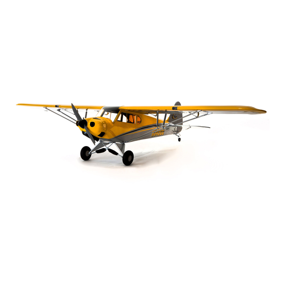
ASSEMBLY INSTRUCTIONS
Check out our website for more information on other exciting Model Tech products!
hTTP://MoDelTeCh.GlobAlhobby.CoM
Completely Prebuilt and Covered with Iron-On Covering Material
l
Accepts Glow Power and Brushless Electric Power Systems
l
Model Tech Co., Ltd.
Stable, Predictable Flight Characteristics
l
Hong Kong
Fiberglass Cowling and Aluminium Landing Gear Bracket
l
Clear Moulded Windshield and Side Windows
© 2008, Model Tech Co., Ltd.
l
Complete Hardware Set - Wheels, Pushrods, Fuel Tank, Clevises, Etc.
All Rights Reserved
l
Version 1 January 2008
Fast and Easy Assembly - Over 100 High-Resolution Photos to Guide You
l
SPeCiFiCATioNS
Wing Span: 81 Inches (2057mm)
Wing Area: 900 Square Inches (58.1dm
l
Weight rTF: 6.5-7.5 Pounds (2.9-3.4kg)
l
Functions: Ailerons, Elevator, Rudder, Flaps and Throttle
engine required (Glow Version): .46 - .61 Two-Stroke or .52 - .70 Four-Stroke
l
Power System required (electric Version): 4120/05 Brushless Outrunner / 80 Amp Brushless ESC / 4 Cell 4000mAH LiPO
Made in China
FeATureS
2
)
length: 50.75 Inches (1289mm)
l
2
Wing loading: 17-19 Ounces/Square Foot (52-58gr/dm
)
Page 1
Kit Product Number MT3178D-1
Advertisement
Table of Contents

Related Manuals for Model Tech Super Cub ARF


Summary of Contents for Model Tech Super Cub ARF
- Page 1 Global Hobby Distributors Attn: Global Services 18480 Bandilier Circle Fountain Valley CA 92728-8610 ASSEMBLY INSTRUCTIONS Check out our website for more information on other exciting Model Tech products! hTTP://MoDelTeCh.GlobAlhobby.CoM Fold along dotted line FeATureS Completely Prebuilt and Covered with Iron-On Covering Material Accepts Glow Power and Brushless Electric Power Systems Model Tech Co., Ltd.
-
Page 2: Table Of Contents
In that Model Tech has no control over the final assembly or material used for final assembly, no liability shall be assumed for any damage resulting from the use by the user of the final user-assembled product. By the act of using the final user-assembled product, the user accepts all resulting liability. -
Page 3: Our Recommendations
PArTS liST There really isn't too much else that you'll need to finish your Super Cub ARF. You'll need an in-cowl fueling valve if you're using a glow engine. You'll also need typical modeling supplies, such as foam rubber to protect your receiver and battery. We've provided a complete When it comes time to order replacement parts, we recommend ordering directly from your local hobby retailer. -
Page 4: Lithium Polymer Battery Warnings - Please Read
liThiuM PolyMer bATTery WArNiNGS - PleASe reAD C/G AND bAlANCiNG WArNiNGS AND SAFeTy PreCAuTioNS For All brANDS oF liThiuM PolyMer bATTerieS IMPORTANT It is critical that your aircraft be balanced correctly. Incorrectly balancing your aircraft can cause your aircraft to lose control and crash! Please read and understand the warnings listed in this section. -
Page 5: Tools And Supplies Required
We do not suggest storing your aircraft in an extremely hot environment (like the back of your car in direct sunlight) for any length of this completes the final assembly of your new super cub arF. please read through the next few time. -
Page 6: Kit Contents
M3 x 10mm machine screws and two M3 flat washers. iF yoU Find any parts missing or damaged, please contact yoUr local model tech dealer directly, Using the separate cUstomer service sheet inclUded with yoUr kit. - Page 7 PRO TIP Before installing the side windows, carefully paint the inside edges of the window openings in the fuselage flat black. This eleVATor AND ruDDer CoNTrol SySTeMS will enhance the appearance of the window frames. q (2) 27-1/2" (700mm) Threaded Wires with 90º Bends q (1) 26-3/4"...
-
Page 8: Wing Assembly
MiSCellANeouS WiNG PArTS q Mark and cut out the areas of the cowling necessary to give you access to q (2) M4 x 35mm Machine Screws your engine's high and low speed needle valves, and the muffler. You should q (2) M4 Flat Washers also install an in-cowl fueling valve in a convenient location on the side or bottom of the cowling so that you can fill the fuel tank. - Page 9 CoWliNG iNSTAllATioN you'll NeeD The FolloWiNG PArTS FroM The KiT: q Slide one hinge into each of the four hinge slots in the aileron, making sure q (1) Cowling q (4) M2 x 10mm Flange-Head Wood Screws that you push each hinge in up to the T-Pins. you'll NeeD The FolloWiNG ToolS AND SuPPlieS: IMPORTANT Don't glue the hinges into the aileron yet.
- Page 10 q Allow the C/A to dry for about 15 minutes, then pivot the flap down several times to free up the hinges. STeP 2: iNSTAlliNG The AileroN PuShroD ASSeMblieS IMPORTANT Check the integrity of the hinges after the C/A fully cures by gently pulling on the flap. If one or more hinges feels loose, q Cut away all but one arm from a "4-point"...
- Page 11 q Install the aileron servo into the mounting hole, using the mounting screws q Install the 90º bend in the pushrod wire into the hole that you enlarged in provided with your aileron servo. Make sure to drill 1/16" (1.6mm) diameter pilot the servo arm, using one snap-keeper.
-
Page 12: Horizontal And Vertical Stabilisers Installation
hORIzOnTAl AnD veRTICAl STABIlISeRS InSTAllATIOn ruDDer CoNTrol SySTeM iNSTAllATioN you'll NeeD The FolloWiNG PArTS FroM The KiT: you'll NeeD The FolloWiNG PArTS FroM The KiT: q (1) Fuselage q (9) C/A-Style Hinges q (1) 27-1/2" (700mm) Threaded Wire with 90º Bend q (1) Nylon Snap-Keeper q (1) Horizontal Stabiliser with Elevator Halves q (2) M4 x 35mm Machine Screws... - Page 13 q Remove the elevator halves and hinges from the horizontal stabiliser and set them aside for now. q Install the control horn and backplate, using two M2 x 20mm machine screws, then use wire cutters to cut the top of the screws off flush with the control horn backplate.
- Page 14 eleVATor CoNTrol SySTeM iNSTAllATioN q Look from the front of the aircraft at both the wing and the stabiliser. When you'll NeeD The FolloWiNG PArTS FroM The KiT: aligned properly, the stabiliser should be parallel to the wing. q (1) 27-1/2" (700mm) Threaded Wire with 90º Bend q (1) Nylon Snap-Keeper If the stabiliser is not parallel to the wing, remove the stabiliser and sand q (1) 26-3/4"...
- Page 15 q Secure one end of the silicone fuel tubing onto the end of the clunk. q Remove the rudder and hinges from the vertical stabiliser and set them aside for now. q Slide the silicone fuel tubing, with the clunk attached, onto the end of the q Push the stabiliser down into the mounting slot, then draw a line on each aluminium fuel pick-up tube (straight tube).
-
Page 16: Tail Wheel Installation
TAil Wheel iNSTAllATioN q Slide the adjustable pushrod connector assembly onto the pushrod wire, you'll NeeD The FolloWiNG PArTS FroM The KiT: then install the servo horn onto the servo, making sure that the servo horn is q (1) Prebent Tail Wheel Wire q (3) M3 x 12mm Wood Screws angled approximately 30 degrees from centre. -
Page 17: Main Landing Gear Installation
STeP 2: iNSTAlliNG The ThroTTle PuShroD Wire STeP 3: iNSTAlliNG The TAil Wheel q Centre the rudder, then loosen the machine screw in the steering arm and align the tail wheel wire with the bottom of the rudder. When satisfied with the alignment, tighten the machine screw firmly. q Mark the location of the throttle pushrod exit hole on the firewall. - Page 18 STeP 2: iNSTAlliNG The Wire STruTS IMPORTANT When you drill the holes through the engine mounting beams in the next procedure, be careful that you drill the holes straight down and not at an angle. q Mark the locations of the engine mounting holes onto the engine mounting beams. q Slide one bungee cover onto the lower (longer) section of each wire strut.
-
Page 19: Motor Installation - Electric Version
STeP 3: iNSTAlliNG The MAiN GeAr WheelS q Measure the distance between the holes in the two engine mounting beams. IMPORTANT One side of each main gear wheel is milled to fit the head of the machine screw. This is the outside of the wheel and As an example, for the Magnum XL .52RFS engine used in this aircraft, also has predrilled holes for the wheel cover. -
Page 20: Engine Installation - Glow Version
STeP 1: iNSTAlliNG your MoTor MouNT AND ProPeller ADAPTer IMPORTANT Two sets of motor mounting holes are predrilled through the motor mounting box, one set for a four-hole radial backplate mount and one set for mounting directly into the back of the motor. If your motor or its backplate mount uses a different q After the epoxy sets up, glue one piece of balsa triangle support between mounting hole pattern, you will need to drill new mounting holes through the motor mounting box to match.
Need help?
Do you have a question about the Super Cub ARF and is the answer not in the manual?
Questions and answers