Advertisement
Quick Links
Owner's Manual
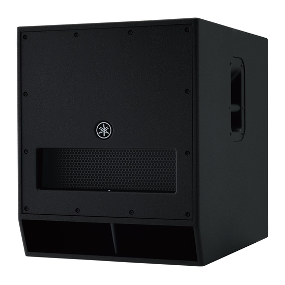
Introduction
Thank you for purchasing the Yamaha DXS18 Powered Subwoofer. Please read this manual thoroughly to
ensure optimum long-term use of your DXS18.
Keep the manual in a safe place for future reference.
• Please read the PRECAUTIONS on the reverse side of this manual before use.
• The illustrations as shown in this manual are for instructional purposes only.
• The company names and product names used in this manual are the trademarks or registered trade-
marks of their respective companies.
Included accessories and optional accessories
Included accessories
Optional accessories
• AC power cord
• Speaker cover (SPCVR-18S01)
• Owner's manual (this leaflet)
• Wheels (SPW-1; 4 pieces)
• Technical Specifications
w
q
r
e
q Pole sockets
i OUTPUT jacks
Adapts to commercially available speaker poles of 35 mm diameter and
These are balanced output XLR jacks for connecting full-range speak-
M20 screws. For detail on installing speaker poles, refer to "Installing a
ers or additional DXS18 units. The output signal can be switched via
Speaker Pole."
the THROUGH/HPF POST switch (o).
L/R output from the OUTPUT jacks correspond to L/R input to the
w Feet cups
INPUT jacks. The mixed signal of L/R is not output.
When stacking multiple DXS18 units, align the rubber feet of the upper
o THROUGH/HPF POST switch
DXS18 unit to the feet cups of the lower.
Switches the signals output from the OUTPUT jacks (i).
CAUTION
Do not stack more than two DXS18 units.
Make sure to lower the input level when switching.
e Front LED
• THROUGH: Outputs unaffected signals from INPUT jacks (u).
Turns on when the power is on. Lights more brightly when the output
Select when using HPF of the connected speaker or connecting addi-
limiter is active. Using FRONT LED DISABLE switch (!9 ) enables
tional DXS18 units.
you keep the LED always off.
• HPF POST: Outputs signal input from INPUT jacks (u) after pass-
r Wheel mounting holes
ing through a HPF. The cutoff frequency of the high pass filter is the
Optional SPW-1 wheels can be installed to the holes. For details on
frequency specified with the X-OVER switch (!2 ) . Because the out-
installing the wheels or special precautions you should take, please
put level from the OUTPUT jacks is linked to the LEVEL control
refer to the relevant manual for the wheels.
(!1 ) , the levels of this unit and the full-range speaker change simulta-
neously.
t AC IN socket
!0 PEAK indicator
Connect the supplied AC power cord here. First, connect the power
cord to the DXS18, then insert the power cord plug into the AC outlet.
Lights red when the input level reaches 3 dB below clipping. If the indi-
cator lights frequently, adjust the volume of the input source or lower
CAUTION
the LEVEL control (!1 ) so that the indicator flashes only briefly at the
Turn off the power before you connect or disconnect the
highest input levels.
power cord.
!1 LEVEL control
Adjusts the output level.
y Power switch
Turns the power to the unit on ( ) or off (
).
!2 X-OVER switch
If you are using multiple units, turn on the power to each unit one by
Specifies the crossover frequency at 120 Hz, 100 Hz, or 80 Hz. The
one. If you turn on the power to multiple units simultaneously, a tempo-
output from the unit is processed through a low pass filter to cut the
rary drop in the power voltage may occur, possibly resulting in abnor-
range of the selected frequency or higher. When setting THROUGH/
mal operation of the units.
HPF POST switch (o) to [HPF POST], the output signals from the
Also, rapidly turning the unit on and off in succession can cause it to
OUTPUT jacks are processed through a high pass filter to cut the range
malfunction. After turning the unit off, wait for about 5 seconds before
of the selected frequency or lower, and the crossover frequency is
turning it on again.
linked to that of the connected speaker.
u INPUT jacks
These are balanced input XLR jacks (line-level), and this device out-
puts the mixed signals of L and R.
1
Features
ZR38060
EN
1,020 W power and 136 dB max. SPL and LF extension down to 32 Hz
Powered by a 1,020 W amplifier with an 18" woofer with a 4" voice coil and housed in a sturdy band-
pass type enclosure, the DXS18 is able to realize 136 dB maximum SPL, and an extended LF down to 32
Hz with exceptional clarity and minimal distortion.
Flexible features
• D-XSUB: D-XSUB is a DSP technology that gives users additional dynamic control of the frequency
range to meet the demands of a variety of applications or musical styles.
• Selectable X-OVER (80/100/120 Hz): Selecting the cut-off frequency and LPF/HPF settings offers
users more flexibility to adapt to various applications.
• Cardioid mode: The Cardioid mode setting adds additional control of low frequencies for sub-woofer
arrays of two or more DXS18 speakers, effectively reducing the SPL of bass directed towards the stage
while increasing the bass levels directed towards the audience.
Reliability
The DXS18 features advanced protection circuits in the speaker unit, amplifier unit, and power supply
that ensure optimum reliability and extended equipment life.
Durability
The DXS18's sturdy plywood cabinet is covered with an extremely durable LINE-X finish that provides
added protection from outside elements and duress.
Fast and easy setup
M20 and Ø35 dual pole sockets allow for more flexible set up, while optional casters are also available
for improved portability.
Controls and functions
u
o
i
t y
!3 D-XSUB switch
Switches the low-range frequency response characteristics.
• NORMAL: A generic setting corresponding to various applications.
• BOOST: Boosts the frequency range enhancing and providing punch
to the sound.
• XTD LF (eXTenDed LF): Extends the bottom of the low frequency
range.
!4 CARDIOID switch
Connection of multiple DXS18 units enables the use of Cardioid mode.
CAUTION
For details on Cardioid mode and using the switch, refer to "Setup of
Cardioid Mode" on the opposite page.
!5 POLARITY switch
Switches the polarity of the unit, normal or inverted. When the polarity
is inverted, the INVRT indicator lights.
In most cases, this should be set to normal; however, the inverted set-
ting may improve low-range response, depending on the type and loca-
tion of the speaker system. Select a setting that produces the best low-
end sound.
!6 LIMIT indicator
Lights when the output limiter is active. The output limiter operates in
order to protect the speaker and amplifier, attenuating the output signal
to the amplifier. If the indicator lights frequently, adjust the volume of
the input source or lower the LEVEL control (!1 ) so that the indicator
only occasionally lights at the highest input levels.
!7 PROTECTION indicator
Lights when the protection system is active. The protection system
operates and the speaker output is muted in the following situations.
• If amplifier overheating is detected.
• If overcurrent is detected.
• Immediately after turning the power on. (The protection system is
activated to prevent noise and the indicator lights for about two sec-
onds. The indicator turns off when the power supply has started nor-
mally.)
!8 POWER indicator
Lights when the power is on.
!9 FRONT LED DISABLE switch
Turns the FRONT LED at the front of the unit on or off. The LED lights
when this switch is set to off. Turn this switch on to disable the LED.
Input the output signal from a source, such as a mixer, to the INPUT jack of the DXS18, and input the out-
put signal from the OUTPUT jack of the DXS18 to the input jack of a full-range speaker.
• X-OVER switch (!2 )
It is recommended that you match the crossover frequency (the cutoff frequency of the low pass filter)
of the DXS18 and the cutoff frequency of the high pass filter of the full-range speaker. The same fre-
quency range output from the DXS18 and the full-range speaker may cause interference with each other
and degrade the frequency characteristics.
• THROUGH/HPF POST switch (o)
If the full-range speaker is properly equipped with a high pass filter, you should set this to
[THROUGH]. The [THROUGH] setting enables you to control the level independently and minimize
signal delay. If the full-range speaker is not equipped with a high pass filter or the high pass filter in the
full-range speaker cannot be set to the same cutoff frequency as that of the low pass filter of the DXS18,
set this to [HPF POST] to use the high pass filter in the DXS18.
Combination and setting examples
Full-range
speaker
From
mixer
CAUTION
If multiple powered speakers are connected in daisy-chain fashion, turn each device on in
sequence starting from the one nearest to the sound source, and turn them off starting from the
one farthest from the sound source.
Combination of monaural DXS18 and stereo full-range speakers
!0
!6
Full-range speaker
!7
!8
!1
!9
!5
!2
!3
!4
Combination of stereo DXS18 and stereo full-range speakers
NOTE
The L and R jacks are interchangeable; there is no difference in behavior between them.
Full-range speaker
DXS18
Basic Setup
The pole sockets of the DXS18 are compatible with commercially available speaker poles of 35 mm diame-
ter and M20 screws.
Using the high pass filter in the
Using the high pass filter in
connected full-range speaker
the DXS18
Installing optional wheels SPW-1 at the back of the DXS18 enables you to transport the unit easily. To
install the wheels, use the screws installed in the DXS18 unit, after removing them from the unit.
Full-range
Please do not use the speaker once the screws are removed. This causes air leaks to occur in enclosure,
speaker
resulting in undesirable performance.
DXS18
!2
!2
o
o
Full-range speaker
From mixer
DXS18
To full-range speaker
Mixer
* If any specific problem should persist, please contact your Yamaha dealer.
From mixer
Full-range speaker
To full-range speaker
DXS18
* The contents of this manual apply to the latest specifications as of the printing date. Since Yamaha makes continuous
Mixer
Installing a Speaker Pole
Ø35
M20 screw
Installing Wheels
CAUTION
• For details on installing the wheels or special precautions you should take, please refer to the
relevant manual for the wheels.
• Do not install wheels other than the SPW-1.
Troubleshooting
Symptom
Possible causes
Possible solution
The power cord is not con-
Power does not turn on.
Connect the power cord properly.
nected properly.
The protection system has
Power suddenly turned
Turn off the power, wait until the amplifier cools down,
been activated, shutting
off.
and then turn on again.
down the power supply.
The cable is not con-
No sound.
Connect the cable to the INPUT jack properly.
nected properly.
The protection circuit has
Wait until the amplifier cools down. If the unit doesn't
Sound is interrupted
been activated, muting the
automatically reset itself, turn off the power, and then
suddenly.
output.
on again.
Sound howls (feed-
A microphone is directed
Keep the speaker away from the area where the
back).
toward the speaker.
microphone picks up the sound.
The sound from each
The settings for each
Set each switch of each speaker to the same posi-
speaker differs (if multi-
speaker differ.
tion.
ple speakers are used.)
Lower the volume of the input device so that the
Input volume is excessive.
PEAK indicator lights only occasionally.
Sound is distorted.
Output volume is exces-
Lower the output level with the LEVEL control so that
sive.
the LIMIT indicator lights only occasionally.
General Specifications
General Specifications
DXS18
System Type
Powered subwoofer, band-pass type
Frequency Range (-10 dB)
32 Hz–120 Hz
Measured Maximum SPL (Peak) Pink Noise @1m 136 dB SPL
Dynamic
1,020 W
Power
Power Rating
Continuous
800 W
Amplifier
Power Consumption (1/8 output power) 100 W
Components
LF
18" cone, 4" voice coil
Dimensions (W × H × D; including rubber feet)
563 × 683 × 721 mm
Weight
49.7 kg
Handles
Steel, side × 2
Pole Sockets (top surface)
Ø35 mm (depth: 80 mm), M20 (threaded depth: 25 mm)
Input
XLR3-31 × 2
Connectors
Output
XLR3-32 × 2 (THROUGH or HPF POST)
Input Sensitivity (LEVEL: center)
+10 dBu
Maximum Input Level
+24 dBu
improvements to the product, this manual may not apply to the specifications of your particular product. To obtain the latest
manual, access the Yamaha website then download the manual file. Since specifications, equipment or separately sold
accessories may not be the same in every locale, please check with your Yamaha dealer.
Advertisement

Related Manuals for Yamaha DXS18


Summary of Contents for Yamaha DXS18
- Page 1 Powered by a 1,020 W amplifier with an 18" woofer with a 4" voice coil and housed in a sturdy band- Input the output signal from a source, such as a mixer, to the INPUT jack of the DXS18, and input the out-...
- Page 2 The above warning is located on the rear of the unit. • Input the same signal to all the DXS18 units to be used. You can also use the units connected in daisy death from electrical shock, short-circuiting, L’avertissement ci-dessus est situé...
Need help?
Do you have a question about the DXS18 and is the answer not in the manual?
Questions and answers