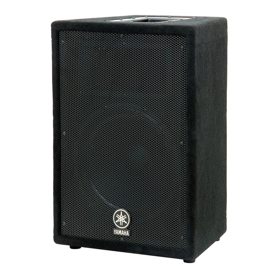
Active servo processing subwoofer system (12 pages)
Summary of Contents for Yamaha A10
Page 1
SPECIFICATIONS & DIMENSIONS ........3 NEUTRIK NL4FC PLUG WIRING..........3 CROSSOVER ................4 DISASSEMBLY PROCEDURE ..........9 A10/A12/A15 ................9 A12M ..................12 A15W ..................15 PARTS LIST 011750 HAMAMATSU, JAPAN Copyright (c) Yamaha Corporation. All rights reserved. PDF-K103 ’04.11...
Page 2
IMPOR TANT NOTICE This manual has been provided for the use of authorized Yamaha Retailers and their service personnel. It has been assumed that basic service procedures inherent to the industry, and more specifically Yamaha Products, are already known and under- stood by the users, and have therefore not been restated.
SPEAKER SYSTEM/SUBWOOFER A10/A12/A12M/A15/A15W DISASSEMBLY PROCEDURE A10/A12/A15 Metal Handle Rubber Foot (Time required: About 1 minutes) (Time required: About 2 minute) Remove the screw marked [42]. The rubber foot can Remove the ten (10) screws marked [5A]. The metal then be removed. (Photo.3) handle then removed.
Page 10
SPEAKER SYSTEM/SUBWOOFER A10/A12/A12M/A15/A15W Speaker(Woofer) (Time required: About 3 minutes) A10: Remove the eight (8) screws marked [5B]. The Remove the eight (8) screws marked [23]. The metal speaker(woofer) can then be removed. (Photo.5) grille can then be removed. (Photo.4) A12/ A15: Remove the eight (8) screws marked [6].
Page 11
SPEAKER SYSTEM/SUBWOOFER A10/A12/A12M/A15/A15W Terminal Plate, Network (Time required: About 2 minutes) Remove the four (4) screws marked [12B]. The Remove the two (2) screws marked [39] and the two network and terminal plate can then be removed. (2) hexagonal nuts marked [38]. The neutrik NL4MP (Photo.8)
Page 12
SPEAKER SYSTEM/SUBWOOFER A10/A12/A12M/A15/A15W A12M Metal Handle Rubber Foot (Time required: About 1 minutes) (Time required: About 2 minute) Remove the screw marked [42]. The rubber foot can Remove the ten (10) screws marked [5]. The metal then be removed. (Photo.3) handle then removed.
Page 13
SPEAKER SYSTEM/SUBWOOFER A10/A12/A12M/A15/A15W Speaker(Woofer) (Time required: About 3 minutes) Remove the eight (8) screws marked [23]. The metal Remove the eight (8) screws marked [6]. The grille can then be removed. (Photo.4) speaker(woofer) can then be removed. (Photo.5) [23] Speaker(Tweeter)
Page 14
SPEAKER SYSTEM/SUBWOOFER A10/A12/A12M/A15/A15W Terminal Plate, Network (Time required: About 2 minutes) Remove the four (4) screws marked [12B]. The Remove the two (2) screws marked [39] and the two network and terminal plate can then be removed. (2) hexagonal nuts marked [38]. The neutrik NL4MP (Photo.8)
Page 15
SPEAKER SYSTEM/SUBWOOFER A10/A12/A12M/A15/A15W A15W Metal Handle Rubber Foot (Time required: About 1 minutes) (Time required: About 2 minute) Remove the screw marked [42]. The rubber foot can Remove the ten (10) screws marked [5]. The metal then be removed. (Photo.3) handle then removed.
Page 16
SPEAKER SYSTEM/SUBWOOFER A10/A12/A12M/A15/A15W Speaker(Woofer) (Time required: About 3 minutes) Remove the eight (8) screws marked [7]. The Remove the eight (8) screws marked [23]. The metal speaker(woofer) can then be removed. (Photo.5) grille can then be removed. (Photo.4) [23] [23]...
PARTS LIST CONTENTS OVERALL ASSEMBLY A10 ..................2 A12 ..................3 A12M ..................4 A15..................5 A15W ..................6 Notes : DESTINATION ABBREVIATIONS A : Australian model M : South African model B : British model O : Chinese model...