Table of Contents
Advertisement
Available languages
Available languages
Safe Operation Practices • Set-Up • Operation • Maintenance • Service • Troubleshooting • Warranty
O
'
M
peratOr
s
anual
Two-Stage Snow Thrower — Storm 3090
WARNING
READ AND FOLLOW ALL SAFETY RULES AND INSTRUCTIONS IN THIS MANUAL
BEFORE ATTEMPTING TO OPERATE THIS MACHINE.
FAILURE TO COMPLY WITH THESE INSTRUCTIONS MAY RESULT IN PERSONAL INJURY.
TROY-BILT LLC, P.O. BOX 361131 CLEVELAND, OHIO 44136-0019
Printed In USA
Form No. 769-05011
(June 18, 2009)
Advertisement
Table of Contents

Related Manuals for Troy-Bilt storm 3090


Summary of Contents for Troy-Bilt storm 3090
- Page 1 READ AND FOLLOW ALL SAFETY RULES AND INSTRUCTIONS IN THIS MANUAL BEFORE ATTEMPTING TO OPERATE THIS MACHINE. FAILURE TO COMPLY WITH THESE INSTRUCTIONS MAY RESULT IN PERSONAL INJURY. TROY-BILT LLC, P.O. BOX 361131 CLEVELAND, OHIO 44136-0019 Printed In USA Form No. 769-05011...
-
Page 2: Table Of Contents
Choose from the options below: ◊ Visit us on the web at www.troybilt.com ◊ Call a Customer Support Representative at (800) 828-5500 or (330) 558-7220 ◊ Write us at Troy-Bilt LLC • P.O. Box 361131 • Cleveland, OH • 44136-0019... -
Page 3: Safe Operation Practices
Important Safe Operation Practices WARNING! This symbol points out important safety instructions which, if not followed, could endanger the personal safety and/or property of yourself and others. Read and follow all instructions in this manual before attempting to operate this machine. Failure to comply with these instructions may result in personal injury. - Page 4 Safe Handling of Gasoline Never run an engine indoors or in a poorly ventilated area. Engine exhaust contains carbon monoxide, an odorless To avoid personal injury or property damage use extreme care and deadly gas. in handling gasoline. Gasoline is extremely flammable and the Do not operate machine while under the influence of vapors are explosive.
- Page 5 Clearing a Clogged Discharge Chute According to the Consumer Products Safety Commission (CPSC) and the U.S. Environmental Protection Agency (EPA), Hand contact with the rotating impeller inside the discharge this product has an Average Useful Life of seven (7) years, chute is the most common cause of injury associated with snow or 60 hours of operation.
-
Page 6: Safety Symbols
Safety Symbols This page depicts and describes safety symbols that may appear on this product. Read, understand, and follow all instructions on the machine before attempting to assemble and operate. Symbol Description READ THE OPERATOR’S MANUAL(S) Read, understand, and follow all instructions in the manual(s) before attempting to assemble and operate WARNING—... -
Page 7: Assembly & Set-Up
Assembly & Set-Up Contents of Carton • One Snow Thrower • Two Replacement Auger Shear Pins • One Product Registration Card • One Snow Thrower Operator’s • Hex Rod • Chute Assembly Manual Assembly Remove all loose parts before assembling. Chute Control Head Handle Assembly Place the shift lever in the Forward-6 position... - Page 8 Finish securing chute control head to chute support Insert hex rod into chute control head. Push rod as far into bracket with wing nut and hex screw removed in step 1. chute control head as possible, keeping the hole in the hex See Fig.
- Page 9 Set-Up Push the rod toward the control panel until the hole in the hex rod lines up with the hole in the chute control input closest to the chute control head and insert the cotter pin. Shear Pins See Fig. 3-8. A pair of replacement auger shear pins and bow tie cotter pins Note: The second hole is used to achieve further are included with your snow thrower.
- Page 10 Fuel Recommendations Checking Oil Level Use automotive gasoline (unleaded or low leaded to minimize CAUTION: The engine is shipped with oil in the combustion chamber deposits) with a minimum of 87 octane. engine. You must, however, check the oil level prior Gasoline with up to 10% ethanol or 15% MTBE (Methyl Tertiary to operating the snow thrower.
-
Page 11: Adjustments
Adjustments Auger Control WARNING! Prior to operating your snow thrower, Skid Shoes carefully read and follow all instructions below. The snow thrower skid shoes are adjusted upward at the factory Perform all adjustments to verify your snow thrower for shipping purposes. Adjust them downward, if desired, prior is operating safely and properly. -
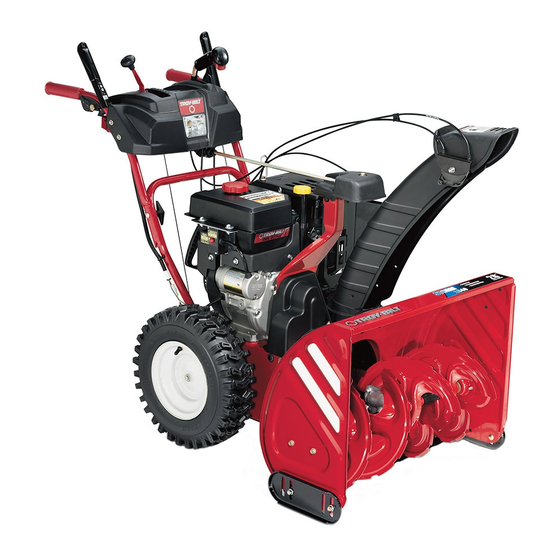
Page 12: Controls
Controls and Features Shift Lever Drive Control Chute Directional Control Auger Control Heated Grips Gas Cap Chute Assembly Oil Fill Clean Out Tool Primer Key Electric Starter Outlet Choke Electric Starter Throttle Button Augers Recoil Starter Skid Shoe Oil Drain Handle Figure 4-1 Choke Control... - Page 13 Throttle Control Auger Control The throttle control is located on the rear of the engine. It regulates the speed of the engine and will shut off the engine when moved into the STOP position. Primer Pressing the primer forces fuel directly into the engine’s carburetor to aid in cold-weather starting.
- Page 14 Chute Directional Control Heated Grips To activate the heated grips, move the switch found on the rear of the dash panel into the ON position. Chute Clean-Out Tool WARNING! Never use your hands to clear a clogged chute assembly. Shut off engine and remain behind handles until all moving parts have stopped before unclogging.
-
Page 15: Operation
Operation Starting the Engine Plug the extension cord into the electric outlet located on the engine. Plug the other end of extension cord into WARNING! Always keep hands and feet clear of a three-prong 120-volt, grounded, AC outlet in a well- moving parts. -
Page 16: Stopping The Engine
To Engage Drive Recoil Starter CAUTION! Do not pull the starter handle while the With the throttle control in the Fast (rabbit) position, move engine running. shift lever into one of the six forward (F) positions or two reverse (R) positions. Select a speed appropriate for the snow conditions and a pace you’re comfortable with. -
Page 17: Maintenance & Adjustment
Maintenance & Adjustments Maintenance Tire Pressure Warning: Under any circumstance do not exceed Engine manufacturer’s recommended psi. Equal tire Refer to the Engine Maintenance section. pressure should be maintained at all times. Excessive pressure when seating beads may cause tire/rim Shave Plate and Skid Shoes assembly to burst with force sufficient to cause The shave plate and skid shoes on the bottom of the snow... - Page 18 Adjustments Wheels At least once a season, remove both wheels. Clean and coat the Shift Cable axles with a multipurpose automotive grease before reinstalling wheels. If the full range of speeds (forward and reverse) cannot be achieved, adjust the shift cable as follows: Auger Shaft Place the shift lever in the fastest forward speed position.
- Page 19 Drive Control Chute Control Rod When the drive control is released and in the disengaged “up” To adjust the chute control rod, proceed as follows: position, the cable should have very little slack. It should NOT be Remove the cotter pin from the hole closest to the chute tight.
-
Page 20: Engine Maintenance
Engine Maintenance WARNING! Periodic inspection and adjustment of the engine is essential if To prevent accidental start-up, shut off high level performance is to be maintained. Regular maintenance the engine and remove the key before performing will also ensure a long service life. The required service intervals any type of engine maintenance. -
Page 21: Spark Plug
Spark Plug Check that the spark plug washer is in good condition and thread the spark plug in by hand to prevent cross- WARNING! DO NOT check for spark with spark threading. plug removed. DO NOT crank engine with spark After the spark plug is seated, tighten with a spark plug plug removed. -
Page 22: Belt Replacement
Service Belt Replacement Carefully pivot the snow thrower up and forward so that it rests on the auger housing. Auger Belt Remove the frame cover from the underside of the snow thrower by removing four self-tapping screws which secure To remove and replace your snow thrower’s auger belt, proceed it. - Page 23 Remove the belt from around the auger pulley, and slip the Drive Belt belt between the support bracket and the auger pulley. To remove and replace your snow thrower’s drive belt, proceed See Fig. 8-5. as follows: Allow the engine to run until it is out of fuel. Do not attempt to pour fuel from the engine.
- Page 24 Back out the stop bolt to increase the clearance between Remove the frame cover from the underside of the snow the friction wheel disc and friction wheel. See Fig. 8-7. thrower by removing four self-tapping screws which secure it. See Fig. 8-8. Stop Bolt Figure 8-7 Figure 8-8...
-
Page 25: Troubleshooting
Troubleshooting Problem Cause Remedy Engine fails to start Choke not in CHOKE position. Move choke to CHOKE position. Spark plug wire disconnected. Connect wire to spark plug. Fuel tank empty or stale fuel. Fill tank with clean, fresh gasoline. Engine not primed. Prime engine as instructed in the Operation Section. -
Page 26: Replacement Parts
Replacement Parts Component Part Number and Description 929-0071 Extension Cord, 110V 954-04195 Auger Drive Belt 954-04201 Wheel Drive Belt 684-04159 Friction Wheel Assembly 935-04054 Friction Wheel Rubber 925-04213 Lamp, 12.5V, 37.5W 738-04124A Shear Pin, 1.50 714-04040 Bow-tie Cotter Pin 790-00091 Slide Shoe, Deluxe 731-2643 Chute Clean-out Tool... - Page 27 Attachments & Accessories The following attachments and accessories are available for your Storm 3090 snow thrower. Phone (800) 828-5500 for information regarding compatibility, price and availability (have your full model number and serial number ready). Model Number Description 753-05762A Heated Grips...
- Page 28 Notes Notes...
- Page 29 12 — n ection oteS...
- Page 30 MTD CONSUMER GROUP INC (MTD), the California Air Resources Board (CARB) and the United States Environment Protection Agency (U. S. EPA) Emission Control System Warranty Statement (Owner’s Defect Warranty Rights and Obligations) EMISSION CONTROL SYSTEM COVERAGE IS APPLICABLE TO CERTIFIED ENGINES PURCHASED IN CALIFORNIA IN 2005 AND THERE- AFTER, WHICH ARE USED IN CALIFORNIA, AND TO CERTIFIED MODEL YEAR 2005 AND LATER ENGINES WHICH ARE PURCHASED AND USED ELSEWHERE IN THE UNITED STATES.
- Page 31 (4) Repair or replacement of any warranted part under the warranty provisions of this article must be performed at no charge to the owner at a warranty station. (5) Notwithstanding the provisions of Subsection (4) above, warranty services or repairs must be provided at all MTD distribution centers that are franchised to service the subject engines.
- Page 32 MANUFACTURER’S LIMITED WARRANTY FOR The limited warranty set forth below is given by Troy-Bilt LLC with c. Service completed by someone other than an authorized service respect to new merchandise purchased and used in the United States dealer. and/or its territories and possessions, and by MTD Products Limited d.
- Page 33 Medidas importantes de seguridad • Configuración • Funcionamiento • Mantenimiento • Servicio • Solución de problemas • Garantía anual del peradOr Máquina quitanieve de dos etapas — Storm 3090 ADVERTENCIA LEA Y SIGA TODAS LAS INSTRUCCIONES DE ESTE MANUAL ANTES DE PONER EN FUNCIONAMIENTO ESTA MÁQUINA.
- Page 34 Elija entre las opciones que se presentan a continuación: ◊ Visite nuestro sitio web en www.troybilt.com ◊ Llame a un representante de Asistencia al Cliente al (800) 828-5500 ó (330) 558-7220 ◊ Escríbanos a Troy-Bilt LLC • P.O. Box 361131 • Cleveland, OH • 44136-0019...
- Page 35 Medidas importantes de seguridad ADVERTENCIA! ¡ La presencia de este símbolo indica que se trata de instrucciones importantes de seguridad que se deben respetar para evitar poner en peligro su seguridad personal y/o material y la de otras personas. Lea y siga todas las instrucciones de este manual antes de poner en funcionamiento esta máquina.
- Page 36 Nunca intente realizar ajustes mientras el motor está La palanca de control de la barrena / impulsor es un dispositivo de seguridad. Nunca evite su funcionamiento. en marcha excepto en los casos específicamente De hacerlo la operación de la máquina es riesgosa y puede recomendados en el manual del operador.
- Page 37 Para encender el motor, jale de la cuerda lentamente hasta Verifique frecuentemente la línea de combustible, el que sienta resistencia, luego jale rápidamente. El repliegue tanque, el tapón, y los accesorios buscando rajaduras o rápido de la cuerda de arranque (tensión de retroceso) le pérdidas.
- Page 38 Símbolos de Seguridad Esta página describe los símbolos y figuras de seguridad internacionales que pueden aparecer en este producto. Lea el manual del operador para obtener la información terminada sobre seguridad, reunirse, operación y mantenimiento y reparación. Símbolo Descripción LEA EL MANUAL DEL OPERADOR (S) Lea, entienda, y siga todas las instrucciones en el manual (es) antes de intentar reunirse y funcionar.
- Page 39 Montaje y Configuración Contenido de la caja • Una máquina quitanieve • Dos pasadores de cuchilla de • Una tarjeta para registrar el barrena de repuesto producto • Un Manual del Operador de la • Varilla hexagonal • Canal de montaje Máquina Quitanieve Montaje Manija...
- Page 40 Termine asegurando el cabezal de control del canal a la Inserte la varilla hexagonal dentro del cabezal de control ménsula de soporte del canal con la tuerca de mariposa y del canal. Empuje la varilla tan lejos dentro del cabezal de el tornillo hexagonal retirados en el Paso 1.
- Page 41 Configuración Empuje la varilla hacia el panel de control hasta que el orificio en la varilla hexagonal se alinee con el orificio en la entrada de control del canal lo más cerca posible Pasadores de cuchilla del cabezal de control del canal e inserte el pasador de Su máquina quitanieve trae un par de pasadores de cuchilla de la chaveta.
- Page 42 Recomendaciones sobre el combustible Verificación del nivel de aceite Utilice gasolina para automóviles (sin plomo o con bajo PRECAUCIÓN: El motor se envía con aceite en el contenido de plomo para minimizar los depósitos en la cámara motor. Sin embargo, debe controlar el nivel de de combustión) con un octanaje mínimo de 87.
- Page 43 Los neumáticos son demasiado inflados para propósitos de Control de la barrena envío. Revise la presión de los neumáticos antes de la nieve ¡ADVERTENCIA! Antes de operar su máquina lanzador. Se refieren a la pared lateral del neumático para el quitanieve, lea atentamente y cumpla todas las fabricante de neumáticos recomendado psi y desinflar (o inflar) instrucciones que aparecen a continuación.
- Page 44 Controles y Características Palanca de Cambios Control de Control direccional del canal Transmisión Control de la Barrena Tapón de Agarre combustible Termico Montaje del canal Llenado de aceite Herramienta de limpieza Cebador Llave del canal Salida del arrancador eléctrico Control del Botón del cebador arrancador...
- Page 45 Pare el Interruptor Control de la barrena El pare el interruptor está ubicado en la parte trasera del motor y lo apaga cuando se lo coloca en la posición STOP. Cebador Al presionar el cebador se envía combustible directamente al carburador del motor para ayudar al encendido cuando el clima es frío.
- Page 46 Control direccional del canal Agarre térmico Para activar los agarres térmicos, mueva el interruptor que se encuentra en la parte posterior del panel de instrumentos a la posición ON (conectado). Herramienta de limpieza del canal ¡AdverTenCiA! Nunca use las manos para liberar un montaje de canal tapado.
- Page 47 Funcionamiento Encendido del Motor Conecte el prolongador al tomacorriente situado en el motor. Conecte el otro extremo del prolongador a un ¡AdverTenCiA! Siempre mantenga las manos y tomacorriente de CA, 120 voltios con conexión a tierra, los pies alejados de las partes móviles. No utilice para tres patas, en un área bien ventilada.
- Page 48 Detención del Motor Arrancador de Retroceso ¡PreCAuCión! No tire de la manija del arrancador AdverTenCiA: Para evitar que el motor funcione mientras el motor está en marcha. sin control, nunca deje la máquina sin vigilancia mientras está en marcha. Apague el motor luego de usarlo y saque la llave.
- Page 49 Mantenimiento y Ajustes Mantenimiento Lubricación Motor Eje de engranaje Consulte el Mantenimiento del Motor para motores embalado El eje de engranaje (hexagonal) se debe lubricar al menos una con la máquina para ver el mantenimiento del motor. vez por temporada o tras cada 25 horas de operación. Gire con cuidado la máquina quitanieve hacia arriba y hacia Placa de raspado y zapatas antideslizantes delante de manera que quede apoyada sobre la caja de la...
- Page 50 Ajustes Eje de la barrena Al menos una vez por temporada, quite los pasadores de cuchilla Cable de cambios del eje de la barrena. Rocíe lubricante en el interior del eje y alrededor de los separadores y los cojinetes bridados que se Si no se puede lograr toda la gama de velocidades (avance y encuentran en ambos extremos del eje.
-
Page 51: Figure
Control de la transmisión Varilla de control del canal Cuando se suelta el control de la transmisión y está en posición Para ajustar la varilla de control del canal proceda de la siguiente desenganchada arriba, el cable debe tener muy poco juego. NO manera: debe estar tenso. -
Page 52: Mantenimiento Del Motor
Mantenimiento del motor ¡AdverTenCiA! La inspección y los ajustes periódicos del motor son esenciales Para evitar el arranque si se desea mantener un alto nivel de rendimiento. El accidental, apague el motor y retire la llave antes de mantenimiento regular también garantizará una prolongada realizar cualquier tipo de mantenimiento del motor. - Page 53 Bujía de Encendido Verifique que la arandela de la bujía esté en buenas condiciones y enrósquela manualmente para no estropear ¡AdverTenCiA! NO pruebe la chispa si no está la la rosca. bujía de encendido. NO dé arranque al motor si no Una vez que la bujía esté...
- Page 54 Servicio Cambio de correa Gire con cuidado la máquina quitanieve hacia arriba y hacia delante de manera que quede apoyada sobre la caja de la barrena. Correa de la barrena Saque la cubierta del marco desde debajo de la máquina Para retirar y reemplazar la correa de la barrena de su máquina quitanieve retirando los cuatro tornillos autorroscantes que quitanieve, proceda como se indica a continuación:...
- Page 55 Retire la correa de alrededor de la polea de la barrena y Quite la correa como sigue: Vea la Fig. 8-6.: deslice la misma entre la ménsula de soporte y la polea de Saque la correa de la barrena de la polea del motor. la barrena.
- Page 56 Volver a la detener perno para aumentar el espacio entre Saque la cubierta del marco desde debajo de la máquina el disco de fricción de la rueda y la rueda de fricción. Vea la quitanieve retirando los cuatro tornillos autorroscantes que Fig.
- Page 57 Solución de Problemas Problema Causa Solución El motor no arranca El con trol del cebador no está en la posición Ponga el con trol del cebador en la posición CHOKE (encendido). CHOKE (encendido). Se ha desconectado el cable de la bujía. Conecte el cable a la bujía.
- Page 58 Piezas de Reemplazo Componente Número de pieza y Descripción 929-0071 Cordón prolongador, 110V 954-04195 Correa de transmisión de la barrena 954-04201 Correa de transmisión de la rueda 684-04159 Montaje de rueda de fricción 935-04054 Goma de la rueda de fricción 925-04213 Lámpara, 12,5V, 27,5W 738-04124A...
- Page 59 Aditamentos y Accesorios Los siguientes aditamentos y accesorios son compatibles con el máquina quitanieve Storm 3090. Llame (800) 828-5500 para la información con respecto a la compatibilidad, el precio y la disponibilidad (tener su número de modelo completo y número de serie).
- Page 60 Notas...
- Page 61 12 — n ección otaS...
- Page 62 MTD CONSUMER GROUP, INC. (MTD), el Bordo de Recursos de Aire de California (CARB) y la Agencia de Protección Medioambiental de Estados Unidos (U. S. EPA) Declaración de Garantía del Sistema de Control de Emisiones (Derechos y obligaciones del propietario según la garantía contra defectos) LA COBERTURA DE SISTEMA DE CONTROL DE EMISIÓN ES APLICABLE A MOTORES CERTIFICADOS COMPRADOS EN CALIFORNIA EN 2005 Y A PARTIR DE ENTONCES, QUE SON USADOS EN CALIFORNIA, Y HASTA AÑO 2005 DE MODELO CERTIFICADO Y MOTORES POSTERIORES QUE SON COMPRADOS Y USADOS EN OTRA PARTE EN LOS ESTADOS UNIDOS.
- Page 63 reemplazada según la garantía se garantizará por el resto del período de garantía. Cualquier pieza garantizada que esté programada para reemplazo según el mantenimiento requerido de conformidad con las instruc- ciones escritas de la Subsección (c) se garantiza por el período de tiempo anterior a la primera fecha de reemplazo programada para esa pieza.
- Page 64 Las disposiciones de esta garantía cubren el recurso de reparación helicoidales y neumáticos. única y exclusiva que surge de la venta. Troy-Bilt no se hará responsable de ninguna pérdida o daño incidental o resultante, Accesorios — Troy-Bilt garantiza que los accesorios de este incluyendo sin limitación, los gastos incurridos para los servicios...
Need help?
Do you have a question about the storm 3090 and is the answer not in the manual?
Questions and answers
Where do you fill the oil at, and what brand of oil do you recommend 4 stroke engine oil
You fill the oil on a Troy-Bilt Storm 3090 at the oil fill cap, which is accessed by unscrewing the dipstick. The recommended engine oil is a 4-stroke, high detergent, premium quality motor oil certified to meet or exceed U.S. automobile manufacturer’s requirements for service classification SG or SF. No specific brand is mentioned.
This answer is automatically generated
how to drain gas