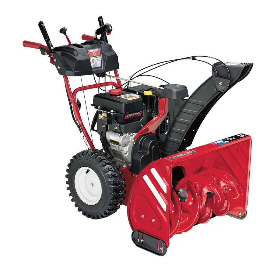
Troy-Bilt Storm 2840 Operator's Manual
Two stage snow thrower
Hide thumbs
Also See for Storm 2840:
- Operator's manual (60 pages) ,
- Operator's manual (56 pages) ,
- Operator's manual (28 pages)
Table of Contents
Advertisement
Available languages
Available languages
Safe Operation Practices • Set-Up • Operation • Maintenance • Service • Troubleshooting • Warranty
O
'
M
peratOr
s
anual
Two-Stage Snow Thrower — Storm 2840
WARNING
READ AND FOLLOW ALL SAFETY RULES AND INSTRUCTIONS IN THIS MANUAL
BEFORE ATTEMPTING TO OPERATE THIS MACHINE.
FAILURE TO COMPLY WITH THESE INSTRUCTIONS MAY RESULT IN PERSONAL INJURY.
TROY-BILT LLC, P.O. BOX 361131 CLEVELAND, OHIO 44136-0019
Printed In USA
Form No. 769-04039
(May 23, 2008)
Advertisement
Table of Contents

Related Manuals for Troy-Bilt Storm 2840


Summary of Contents for Troy-Bilt Storm 2840
- Page 1 READ AND FOLLOW ALL SAFETY RULES AND INSTRUCTIONS IN THIS MANUAL BEFORE ATTEMPTING TO OPERATE THIS MACHINE. FAILURE TO COMPLY WITH THESE INSTRUCTIONS MAY RESULT IN PERSONAL INJURY. TROY-BILT LLC, P.O. BOX 361131 CLEVELAND, OHIO 44136-0019 Printed In USA Form No. 769-04039...
-
Page 2: Table Of Contents
Call a Customer Support Representative at (800) 828-5500 or (330) 558-7220 ◊ Write us at Troy-Bilt LLC • P.O. Box 361131 • Cleveland, OH • 44136-0019 If you have any problems or questions concerning the unit, phone a authorized Troy-Bilt service dealer or contact us directly. -
Page 3: Important Safe Operation Practices
Important Safe Operation Practices WARNING! This symbol points out important safety instructions which, if not followed, could endanger the personal safety and/or property of yourself and others. Read and follow all instructions in this manual before attempting to operate this machine. Failure to comply with these instructions may result in personal injury. - Page 4 Safe Handling of Gasoline To avoid personal injury or property damage use extreme care in handling gasoline. Gasoline is extremely flammable and the vapors are explosive. Serious personal injury can occur when gasoline is spilled on yourself or your clothes which can ignite. Wash your skin and change clothes immediately.
- Page 5 Maintenance & Storage Never tamper with safety devices. Check their proper operation regularly. Refer to the maintenance and adjustment sections of this manual. Before cleaning, repairing, or inspecting machine disengage all control levers and stop the engine. Wait until the auger/impeller come to a complete stop. Disconnect the spark plug wire and ground against the engine to prevent unintended starting.
-
Page 6: Safety Symbols
Safety Symbols This page depicts and describes safety symbols that may appear on this product. Read, understand, and follow all instructions on the machine before attempting to assemble and operate. Symbol WARNING! Your Responsibility—Restrict the use of this power machine to persons who read, understand and follow the warnings and instructions in this manual and on the machine. -
Page 7: Assembly & Set-Up
Assembly & Set-Up Contents of Carton • One Snow Thrower • One Snow Thrower Operator’s Manual Assembly Handle Place the shift lever in the Forward-6 position Observe the lower rear area of the snow thrower to be sure both cables are aligned with roller guides before pivoting the handle upward. - Page 8 Finish securing chute control assembly to chute support bracket with wing nut and hex screw removed earlier. See Fig. 3-4. Figure 3-4 Check that all cables are properly routed through the cable guide on top of the engine. See Fig. 3-5. Figure 3-5 3—...
- Page 9 Tire Pressure Before operating, check tire pressure and reduce pressure in both tires to between 15 psi and 20 psi. Check the side wall of the tire for the recommended maximum tire pressure NOTE: If the tire pressure is not equal in both tires, the machine may not travel in a straight path and the shave plate may wear unevenly.
- Page 10 Auger Control WARNING! Prior to operating your snow thrower, carefully read and follow all instructions below. Perform all adjustments to verify your snow thrower is operating safely and properly. Check the adjustment of the auger control as follows: When the auger control is released and in the disengaged “up”...
-
Page 11: Controls & Features
Controls and Features Drive Control Gas Cap Chute Assembly Clean Out Tool Augers Snow thrower controls and features are described below and illustrated in Fig. 4-1. NOTE: For detailed information on all engine controls, refer to the separate Briggs & Stratton Engine Operator’s Manual. Shift Lever The shift lever is located in the right side of the handle panel and is used to determine ground... - Page 12 Stop Switch The stop switch is located on the rear of the engine. It will shut off the engine when moved into the STOP position. Primer Pressing the primer forces fuel directly into the engine’s carburetor to aid in cold-weather starting. Oil Fill Engine oil level can be checked and oil added through the oil fill.
- Page 13 Chute Directional Control The chute directional control is located on the left side of the dash panel. • To change the direction in which snow is thrown, squeeze the button on the joy-stick and pivot the joy-stick to the right or to the left. •...
-
Page 14: Operation
Operation Starting The Engine Make certain both the auger control and drive control are in the disengaged (released) position. Insert ignition key into slot. Make sure it snaps into place. Do not attempt to turn the key. NOTE: The engine cannot start unless the key is inserted into ignition switch. - Page 15 To Engage Drive With the throttle control in the Fast (rabbit) position, move shift lever into one of the six forward (F) positions or two reverse (R) positions. Select a speed appropriate for the snow conditions and a pace you’re comfortable with. Squeeze the drive control against the handle the snow thrower will move.
-
Page 16: Maintenance & Adjustment
Maintenance & Adjustments Maintenance Engine Refer to the Briggs & Stratton Engine manual packed with your machine for all engine maintenance. Shave Plate and Skid Shoes The shave plate and skid shoes on the bottom of the snow thrower are subject to wear. They should be checked periodically and replaced when necessary. - Page 17 Auger Shaft At least once a season, remove the shear pins from the auger shaft. Spray lubricant inside the shaft and around the spacers and the flange bearings found at either end of the shaft. See Fig. 6-3. Figure 6-3 Adjustments Shift Cable If the full range of speeds (forward and reverse) cannot be...
- Page 18 Drive Control When the drive control is released and in the disengaged “up” position, the cable should have very little slack. It should NOT be tight. NOTE: If excessive slack is present in the drive cable or if the snow thrower’s drive is disengaging intermittently during operation, the cable may be in need of adjustment.
-
Page 19: Service
Service Belt Replacement Auger Belt To remove and replace your snow thrower’s auger belt, proceed as follows: Allow the engine to run until it is out of fuel. Remove the plastic belt cover on the front of the engine by removing the two self-tapping screws. - Page 20 Remove the belt from around the auger pulley, and slip the belt between the support bracket and the auger pulley. See Fig. 7-5. Figure 7-5 Reassemble auger belt by following instructions in reverse order. NOTE: Do not forget to reinstall the shoulder screw and reconnect the spring to the frame after installing a replacement auger belt.
-
Page 21: Friction Wheel Removal
Slip the drive belt off the pulley and between friction wheel and friction wheel disc. See Fig. 7-7. Figure 7-7 Remove and replace belt in the reverse order. NOTE: Engaging the drive control will ease reassembly of the belt. Friction Wheel Removal If the snow thrower fails to drive with the drive control engaged, and performing the drive control cable adjustment fails to correct the problem, the friction wheel may need to be replaced. - Page 22 Carefully remove the hex nut which secures the hex shaft to the snow thrower frame and lightly tap the shaft’s end to dislodge the ball bearing from the right side of the frame. See Fig. 7-9. NOTE: Be careful not to damage the threads on the shaft. Figure 7-9 Carefully position the hex shaft downward and to the left before carefully sliding the friction wheel assembly off the...
-
Page 23: Troubleshooting
Troubleshooting Problem Engine fails to start Choke control not in ON position. Spark plug wire disconnected. Fuel tank empty or stale fuel. Engine not primed. Faulty spark plug. Safety key not inserted . Engine runs erratic Engine running on CHOKE. Blocked fuel line or stale fuel. -
Page 24: Replacement Parts
Replacement Parts Component Phone (800) 828-5500 to order replacement parts or a complete Parts Manual (have your full model number and serial number ready). Parts Manual downloads are also available free of charge at www.troybilt.com. Part Number and Description 929-0071 Extention Cord, 110V 954-04050 Auger Drive Belt... - Page 25 Notes...
- Page 26 MANUFACTURER’S LIMITED WARRANTY FOR The limited warranty set forth below is given by Troy-Bilt LLC with respect to new merchandise purchased and used in the United States and/or its territories and possessions, and by MTD Products Limited with respect to new merchandise purchased and used in Canada and/or its territories and possessions (either entity respectively, “Troy-Bilt”).
- Page 27 Medidas importantes de seguridad • Configuración • Funcionamiento • Mantenimiento • Servicio • Solución de problemas • Garantía anual del peradOr Máquina quitanieve de dos etapas — Storm 2840 ADVERTENCIA LEA Y SIGA TODAS LAS INSTRUCCIONES DE ESTE MANUAL ANTES DE PONER EN FUNCIONAMIENTO ESTA MÁQUINA.
- Page 28 Llame a un representante de Asistencia al Cliente al (800) 828-5500 ó (330) 558-7220 ◊ Escríbanos a Troy-Bilt LLC • P.O. Box 361131 • Cleveland, OH • 44136-0019 Troy-Bilt LLC se reserva el derecho de modificar las especificaciones de los productos, los diseños y el equipo estándar sin previo aviso y sin generar responsabilidad por...
- Page 29 Medidas importantes de seguridad ADVERTENCIA! ¡ La presencia de este símbolo indica que se trata de instrucciones importantes de seguridad que se deben respetar para evitar poner en peligro su seguridad personal y/o material y la de otras personas. Lea y siga todas las instrucciones de este manual antes de poner en funcionamiento esta máquina.
- Page 30 Manejo seguro de la gasolina Para evitar lesiones personales o daños materiales tenga mucho cuidado cuando trabaje con gasolina. La gasolina es sumamente inflamable y sus vapores pueden causar explosiones. Si se derrama gasolina encima o sobre la ropa se puede lesionar gravemente ya que se puede incendiar.
- Page 31 Mantenimiento y Almacenamiento Nunca altere los dispositivos de seguridad. Controle periódicamente que funcionen correctamente. Remítase a las secciones de mantenimiento y ajuste de este manual. Antes de realizar la limpieza, reparar o revisar la máquina, desengrane todas las palancas de control y detenga el motor.
- Page 32 Símbolos de Seguridad Esta página describe los símbolos y figuras de seguridad internacionales que pueden aparecer en este producto. Lea el manual del operador para obtener la información terminada sobre seguridad, reunirse, operación y mantenimiento y reparación. Símbolo ¡ADVERTENCIA! Su para Restringir responsabilidad el uso de esta máquina de poder a personas que leyeron, entienda y siga las advertencias e instrucciones en este manual y en la máquina.
- Page 33 Montaje y Configuración Contenido de la caja • Una máquina quitanieve • Un Manual del Operador de la Máquina Quitanieve Montaje Manija Coloque la palanca de cambios en la posición de avance (F) 6. Observe el área inferior trasera de la máquina quitanieve para asegurarse de que ambos cables estén alineados con las guías rotatorias antes de girar la manija hacia arriba.
- Page 34 Termine de asegurar el montaje de control del canal a la ménsula de soporte del canal con la tuerca de mariposa y el tornillo hexagonal retirados anteriormente. Vea la Fig. 3-4. Figura 3-4 Controle que todos los cables estén adecuadamente dirigidos a través de la guía de cables de la parte superior del motor.
- Page 35 Presión de los neumáticos Antes de cualquier operación, compruebe la presión de ambos neumáticos y reduzca la misma a entre 15 psi y 20 psi. NOTA: si la presión de los neumáticos no es igual en ambos neumáticos, es posible que la máquina no siga una trayectoria recta y que la placa de raspado se desgaste en forma despareja.
- Page 36 Control de la barrena ¡ADVERTENCIA! Antes de operar su máquina quitanieve, lea atentamente y cumpla todas las instrucciones que aparecen a continuación. Realice todos los ajustes para verificar que la máquina está operando con seguridad y correctamente. Compruebe el ajuste del control de la barrena de la siguiente forma: Cuando se suelta el control de la barrena y está...
- Page 37 Controles y Características Control de transmisión Tapón de combustible Manaje del canal Herramienta de limpieza del canal Barrenas Los controles y características de la máquina quitanieve se describen a continuación y se ilustran en la Fig. 4-1. NOTA: Para obtener información detallada sobre todos los controles del motor, consulte el manual de operación Briggs &...
- Page 38 Pare el Interruptor El pare el interruptor está ubicado en la parte trasera del motor y lo apaga cuando se lo coloca en la posición STOP. Cebador Al presionar el cebador se envía combustible directamente al carburador del motor para ayudar al encendido cuando el clima es frío.
- Page 39 Control direccional del canal CONTROL DIRECCIONAL DE CANAL CONTROL DIRECCIONAL DE CANAL PRESIONAR BOT ÓN CANAL INCLINAR HACIA LA IZQUIERDA CANAL INCLINAR HACIA ARRIBA El control direccional del canal está ubicado del lado izquierdo del panel de instrumentos. • Para cambiar la dirección en que se quita la nieve, apriete el botón de la palanca de mando y gire la palanca a derecha o izquierda.
- Page 40 Funcionamiento Encendido del motor Conecte el cable de la bujía a la misma. Compruebe que el lazo de metal del extremo de la bujía esté bien ajustado (dentro de la manga de goma) sobre la punta metálica de la bujía. Asegúrese de que el control de la barrena y el control de la transmisión estén en posición desengranada (sin presionar).
- Page 41 Procedimiento para engranar la transmisión Con el control del regulador en posición rápida (dibujo de un conejo), mueva la palanca de cambios a una de las seis posiciones de avance (F) o de las dos posiciones de reversa (R). Seleccione la velocidad adecuada para el estado de la nieve existente y una velocidad con la que se sienta cómodo.
- Page 42 Mantenimiento y Ajustes Mantenimiento Motor Consulte el manual de operación Briggs & Stratton para motores embalado con la máquina para ver el mantenimiento del motor. Placa de raspado y zapatas antideslizantes La placa de raspado y las zapatas antideslizantes ubicadas en la base de la máquina quitanieve están sujetas a desgaste.
- Page 43 Eje de la barrena Al menos una vez por temporada, quite los pasadores de cuchilla del eje de la barrena. Rocíe lubricante en el interior del eje y alrededor de los separadores y los cojinetes bridados que se encuentran en ambos extremos del eje. Vea la Fig. 6-3. Figura 6-3 Ajustes Cable de cambios...
- Page 44 Control de la transmisión Cuando se suelta el control de la transmisión y está en posición desenganchada arriba, el cable debe tener muy poco juego. NO debe estar tenso. NOTA: Si el cable de transmisión tiene demasiado juego o si la transmisión de la máquina quitanieve se desengrana intermitentemente durante la operación, es posible que deba ajustar el cable.
- Page 45 Servicio Cambio de correa Correa de la barrena Para retirar y reemplazar la correa de la barrena de su máquina quitanieve, proceda como se indica a continuación: Para evitar derrames, coloque un trozo de envoltura de plástico debajo del tapón de combustible y ajuste bien. Saque la cubierta plástica de la correa ubicada en el frente del motor.
- Page 46 Retire la correa de alrededor de la polea de la barrena y deslice la misma entre la ménsula de soporte y la polea de la barrena. Vea la Fig. 7-5. Figura 7-5 Para realizar el reensamblado de la correa de la barrena siga las instrucciones en orden inverso.
- Page 47 Deslice la correa de la transmisión fuera de la polea y de entre la rueda de fricción y el disco de la rueda de fricción. Figura 7-7 Vea la Fig. 7-7. Retire y reemplace la correa en el orden inverso. NOTA: Engranando el control de la transmisión se facilita el montaje de la correa.
- Page 48 Retire con cuidado la tuerca hexagonal y la arandela que sujetan el eje hexagonal al marco de la máquina quitanieve, y golpee suavemente el extremo del eje para desplazar el cojinete de bolas del lado derecho del marco. Vea la Fig. 7-9. NOTA: Tenga cuidado de no dañar las roscas del eje.
- Page 49 Solución de Problemas Problema El motor no arranca El con ON (encendido). Se ha desconectado el cable de la bujía. El depósito de combustible está vacío o el combustible se ha echado a perder. El motor no está cebado. La bujía no funciona correctamente. La llave de seguridad no se ha insertado.
- Page 50 Piezas de reemplazo Componente Llame por teléfono al (800) 828-5500 para solicitar piezas de reemplazo o un Manual de Piezas de Repuesto completo (tenga el número de modelo y número de serie de su máquina a mano). En www.troybilt.com también podrá descargar el Manual de Piezas de Repuesto sin cargo alguno.
- Page 51 Notas...
- Page 52 Las disposiciones de esta garantía cubren el recurso de reparación única y exclusiva que surge de la venta. Troy-Bilt no se hará responsable de ninguna pérdida o daño incidental o resultante, incluyendo sin limitación, los gastos incurridos para los servicios de mantenimiento del césped, o los gastos de arrendamiento para...
Need help?
Do you have a question about the Storm 2840 and is the answer not in the manual?
Questions and answers