Troy-Bilt STORM 8526 Operator's Manual
Two-stage snow thrower
Hide thumbs
Also See for STORM 8526:
- Operator's manual (48 pages) ,
- Operator's manual (28 pages) ,
- Operator's manual (28 pages)
Advertisement
Safety o Assembly
o Operation
o Adjustments
o Maintenance
oTroubleshooting
o Parts Lists oWarranty
®
Two-Stage
Snow Thrower -- STORM 8526
READ SAFETY
RULES
AND mNSTFIUCTmONS CAREFULLY
BEFORE
OPEFIATmON
Warning:
This unitis equippedwith an internalcombustionengineand shouldnot be usedon or nearany unimproved forest-covered, b rush=
coveredor grass=covered l and unlessthe engine'sexhaustsystemis equippedwith a sparkarrestermeetingapplicablelocalor state laws (if any),
If a sparkarresteris used, it shouldbe maintainedin effectiveworkingorder by the operator,Inthe Stateof Californiathe aboveis requiredbylaw
(Section4442 of the CaliforniaPublicResources Code), Otherstates mayhavesimilarlaws,Federallaws applyon federallands,A sparkarrester
for the muffleris availablethroughyournearestengineauthorizedservicedealeror contactthe servicedepartment,RO, Box361131 Cleveland,
Ohio 44136=0019,
PRINTEDIN U,S,A
MTD LLC, RO. BOX 361131 CLEVELAND,
OHIO 44136-0019
FORMNO, 769=01930
06/20/2005
Advertisement
Table of Contents

Related Manuals for Troy-Bilt STORM 8526


Summary of Contents for Troy-Bilt STORM 8526
- Page 1 Safety o Assembly o Operation o Adjustments o Maintenance oTroubleshooting o Parts Lists oWarranty ® Two-Stage Snow Thrower -- STORM 8526 READ SAFETY RULES AND mNSTFIUCTmONS CAREFULLY BEFORE OPEFIATmON Warning: This unitis equippedwith an internalcombustionengineand shouldnot be usedon or nearany unimproved forest-covered, b rush= coveredor grass=covered l and unlessthe engine'sexhaustsystemis equippedwith a sparkarrestermeetingapplicablelocalor state laws (if any), If a sparkarresteris used, it shouldbe maintainedin effectiveworkingorder by the operator,Inthe Stateof Californiathe aboveis requiredbylaw (Section4442 of the CaliforniaPublicResources Code), Otherstates mayhavesimilarlaws,Federallaws applyon federallands,A sparkarrester...
- Page 2 This Operator's Manua_ is an important part of your new snow thrower, mtwHI help you assemble, prepare and maintain the unit for best performance. P_ease read and understand what it says. Table of Contents Safety Labels ............Maintaining Your Snow Thrower ...... Safe Operation Practices ........
- Page 3 1. KEEP AWAY FROMROTATING IMPELLER ANDAUGER. C ONTACT WITH IMPELLER O R AUGER CAN AMPUTATE HANDS ANDFEET. 2. USECLEAN-OUT TOOL TO UNCLOG DISCHARGE C HUTE. 3. DISENGAGE CLUTCH L EVERS, STOP ENGINE, ANDREMAIN BEHIND HANDLES U NTILALL MOVING PARTS HAVE STOPPED BEFORE UNCLOGGING ORSERVICING MACHINE.
-
Page 4: Operation
WARNING: Engine Exhaust, someofitsconstituents, andcertain vehicle compo _ nents contain oremitchemicals k nown to State ofCalifornia t ocause cancer a nd birthdefects or otherreproductive harm. DANGER: Thismachine wasbuilttobeoperated a ccording t otherubsforsafe operation i nthis manual. Aswithanytypeofpower e quipment, carelessness or erroronthepartoftheoperator can Sa.'_e result i nserious injury. -
Page 5: Maintenance And Storage
Operation Maintenance & Storage 1. Donotputhandsorfeetnearrotatingparts, inthe 1. Nevertamper wkhsafety devices.Checktheir proper _) ) auger/impellerhousingor chuteassembly.Contactwith the operationregularly.Referto the maintenanceandadjust- rotatingpartscan amputatehands andfeet. ment sectionsof this manual 2. The auger/impeller control leveris a safetydevice.Never 2. Beforecleaning repairing or inspectingmachinedisen- bypassits operation.Doingso makesthe machineunsafe gage all control leversandstop the engine.Wait until the andmay causepersonalinjury. - Page 6 NOTE:References _ongm or lett siaeof the snow mrowerare ae[ermmea 1, Observethe lowerreararea of the snowthrowerto trom oenmatne un tin tne be sure bothcablesare alignedwith rollerguides operatingpos_on(stana_ng beforepivotingthe handleupward, directtybehindtne snow 2, Securethe handle bytighteningthe plasticwing thrower,facingtne nonage knoblocatedon boththe left and rightsidesof the paneH, handle,Removeand discardany rubberbands,if present,They are for packaging purposesonly,...
- Page 7 5, Removethe flat washerand hairpinclip from theend of the chute directionalcontrol insertthe end of the chute directionalcontrolintothe lowerbracketand securewith the flat washerand hair- pin clipiust removed,If necessary', t he lowerbracket can be adiusted,Refer toChute BracketAdiustment, on Page 13, iMPORTANT: P riorto operatingyoursnowthrower,refer to Auger ControlTeston page 11,Readand followall instructionscarefullyand performall adiustmentsto verify yoursnow throweris operatingsafelyand properly,...
-
Page 8: Know Your Snow Thrower
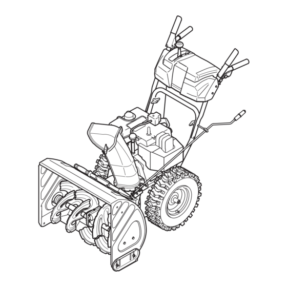
Know Your Snow Thrower Shift Lever / Auger Control Engine Controls WARNING Choke Controm Read, understand, and follow aH instruc- tions and warnings on the machine and in this manual before Figure 1 operating. Choke Contro_ Now that you have set up your snow thrower for Use extreme care operation, get acquainted with its controls and fea- when handling... -
Page 9: Auger Control
Auger Control ignition The ignitionkeyis a safety devise,It mustbe fully insertedin orderfor the engineto start, Removethe ignitionkey whenthesnow throweris not in use, Donot turnthe ignitionkey in an attemptto startthe engine,Doingso maycause it to break, CJean-Out TooJ WARNING: Never use your hands Your Snow to clear a clogged chute assemo... -
Page 10: Stopping The Engine
6, As the enginewarms,slowlyrotatethe chokecontrol Gas & Oit Fill-Up to theOFF position,If the enginefalters,quicklyrotate Servicethe enginewith gasolineand oil as instructedin the choke controlbackto FULLand thenslowlyinto theTecumsehEnginesmanualpackedseparatelywith the OFF positionagain, yoursnowthrower,Readinstructionscarefully, 7, Whendisconnecting the extensioncord, always StartingThe Engine unplugtheend atthe three-prongwalloutlet before 1, Attachsparkplug wire tospark plug, Makecertainthe unplugging the oppositeend from thesnow thrower, metalloop on theend of the sparkplug wire(inside... -
Page 11: To Engage Drive
6. Wipeall snowand moisturefrom the areaaroundthe To Engage Augers engineas wellas the area in and aroundthedrive 1. To engagethe augersand start throwingsnow, controland augercontrol Also,engageand release squeezethe augercontrolagainstthe left handle. bothcontrolsseveraltimes. Releaseto stop the augers. NOTE: Keepthe keyin a safe place.The enginecannot When selecting a Auger Control Test start withoutthe ignitionkey. - Page 12 Auger Controm Referto Auger ControlTeston Page11to adiustthe augercontrol Shift Cable if thefull rangeof speeds(forwardand reverse)cannot be achieved,referto thefigures to the rightand adiust Making theshift cableas follows: 1, Placethe shiftleverin the fastest forwardspeed position, 2, Loosenthe hex nuton the shiftcable indexbracket, See Figure3, 3, Pivotthe bracketdownwardto take up slack in the cable,...
- Page 13 be adiusted,See Figure6, Forclose snow removalon a smoothsurface,raise skid shoeshigheron the augerhousing, • Use a middleor lowerpositionwhenthearea to be clearedis uneven,such as a graveldriveway, Toadiustthe skid shoes: 1, Loosenthe four hexnuts (two on eachside) and carriagebolts,Moveskid shoes to desiredposition, 2, Makecertainthe entire bottomsurfaceof skid shoeis againstthe groundto avoidunevenwearon the skid shoes, 3, Retightennutsand boltssecurely,...
- Page 14 Engine Referto the separateTecumseh Enginesmanual packedwith yourunitfor all enginemaintenance, Lubrication Engine Referto the separateTecumseh Enginesmanual packedwith yourunitfor all enginelubricationinstruc- tions, Gear Shaft The gear (hex)shaft shouldbe lubrbatedat bast once > a seasonor after every25 hoursof operation, 1, Removethelowerframecover by removingthe two screwswhichsecureit, 2, Applya lightcoatingof an aBweathermulti-purpose greaseto the hex shaft, See Figure8,...
- Page 15 Auger Belt Replacement To removeand replaceyoursnow thrower'sauger belt, proceedas follows: 1, Removethe plasticbelt coveron the front of the engineby removingthe two self-tappingscrews, NOTE:Drainthe gasolinefrom the snowthrower,or placea pieceof plasticunderthe gas cap, 2, Carefullypivotthe snowthrowerup andforwardso that it restson the augerhousing,Removethe frame coverfrom the undersideof the snow throwerby removingfourself=tapping screwswhich secureit, 3, Rollthe auger beltoff the enginepulley,...
- Page 16 Augers Theaugersare securedto thespiral shaftwith two shearpinsand cotter pins,if the augershouldstrikea foreignobject or icejam, the snowthroweris designed so that the pinsmay shear,Referto Figure9, • if theaugerswill notturn, checkto seeif the pinshave sheared,One set of replacement s hearpins has been providedwith thesnow thrower,When replacingpins, sprayan oil lubrbant intoshaft beforeinsertingnew pins, Drive...
- Page 17 Friction Whee_ Remova_ if the snowthrowerfailsto drivewith the drivecontrol engaged,and performingthedrive controlcameadiust- menton page 14fails to correctthe problem,the friction wheelmay needto be replaced,Followthe instructions below,Examinethe frictionwheelfor signs of wearor crackingand replaceif necessary o Placetheshift bver in third Forward(F3) position, o Drainthe gasolinefromthe snow thrower,or placea pieceof plasticunderthe gas cap, o Carefullypivotthe snowthrowerup andforwardso that it restson the augerhousing,...
-
Page 18: Preparing Engine
If thesnow throwerwill not be usedfor 30 daysor longer, 1. Removeall gasolinefrom the carburetor and the fuel or if it is the end of the snowseason whenthe last pos= tank to preventgumdepositsfromformingon these sibilityof snow is gone,the equipmentneedsto be stored partsand harmingthe engine. - Page 19 3. Drainfuel tank.Refill with addresses minor fresh fuel. service issues. For 4. Carburetoroutof adiustment. 4. ContactTroy-BiltServiceCenter. further details, contact a Troy-Bilt authorized service center or sail Eng ne overheats 1 CarburetornotadjustedproperY 1 ContactTroy-B t Servce Center 1 (800) 520-5520 for assistance.
- Page 20 StyWe 0...
- Page 21 24, 756_0981A Flat Pulley,Idler, 2,75OD 25, 790-00075 Housing,Bearing,1,85ID 52, 741-0663 Bearing,Flange,,75x 1,0x ,925 26, 790-00080 Bracket,Auger Idlerw/Brake 53, 741-0661A Bearing,Flange,,75x 1,00x ,975 27, 618-04192 GearboxAss'yw/Fitting, Auger 54, 746_04230 ClutchCable,Auger,47,23" 55, 629_0071 ExtentionCord,110V 618-04172 GearboxAss'yw/o Fitting,Auger 28, 684-04078 HousingAss'y,Troy-Bilt,Auger26" 56, 737-3000 GreaseFitting,3/16"...
- Page 22 StyJe 0 ® ,,,,/"...
- Page 23 _i _i i_ iii_ i _ III 631=04133 HandleAssembly,Lock, LH 30, 736=0185 Washer,Flat,,375x ,738x ,063 631=04134A HandleAssembly,Lock, RH 31, 736=0451 Washer,Saddle,320 x ,93 x ,060 684=04105A HandleAss' y, Engagement L H 32, 747=04263 Eye Bolt,ChuteCrank 684=04106A HandleAss'y,Engagement, R H 33, 749=04138 Handle,Lower 710=0224 Screw,#1Od6,0,500 34, 749=04141 Handle,Upper,RH...
- Page 24 StyWe 0...
- Page 25 33, 790_00206 GuideBracket,AugerCable 71, 712_04063 Nut, FlangeLock,5/16_18, N ylon 34, 790-00207 GuideBracket,DriveCable 72, 736-0119 Washer,Lock,5/16 35, 790_00226 Cover,Frame 73, 731_04049A EngineShroud,Troy-Bilt 36, See Chart WheelAssembly 74, 684_04011 Cap, SparkPlugAccess 731-04873 Spacer,1,25x ,75x 3,0 75, 712-3004A Nut, FlangeLock,5/16-18,GR5 38, 738-04188 Axle, ,75x 22"...
-
Page 28: Limited Warranty
Normalwearparts are warrantedto be free fromdefects in materialand retailer, with respect to any product, shall bind Troy-Bilt. During the workmanship fora period of thirty (30) days from thedate of purchase,...
Need help?
Do you have a question about the STORM 8526 and is the answer not in the manual?
Questions and answers