
Summary of Contents for Kipor KDD03
- Page 1 KIPOR Machinery Co., Ltd. Operation Instructions Please read it carefully. It contains important operation guidance for safety. KDD03/05/06/08/10 Loader...
- Page 3 Please mail them to us at any time. Then we can advance the quality of loader and serve you better. If there is any doubt or question, please contact Sales Department of Wuxi KIPOR Machinery Co., Ltd. or your agent.
-
Page 4: Table Of Contents
Contents 3.5 Operation of cab ........16 1.Notes to Safety 1.1 Basic information ........1 Door ON/OFF ..........16 1.2 Notes to pre-start......... 2 Cab lamp ............16 1.3 Notes to operations ........2 Buttons of windshield wiper and cleaner ..16 1.4 Notes to post-operation ...... - Page 5 Check and fill of fuel ........26 and rear half shaft ..........32 Check and filling of oil level in brake fluid cup . 26 Replacement of element of oil return filter ..33 Check of cleaning agent in windshield washer 26 5.9 Check and maintenance every 1000 hours..
-
Page 6: Notes To Safety
Please read the Operation Instructions carefully for safety. 1. Notes to Safety Please read the Operation Instructions carefully and understand it thoroughly before use. Following notes shall be observed for safety concern. In addition, it contains information on Danger, Warning and Caution. -
Page 7: Notes To Pre-Start
Please read the Operation Instructions carefully for safety. 1.2 Notes to pre-start 5) Fix the bucket tightly when loader runs on the 1) Hold rails tightly to avoid the slip. Do not road or a long distance. Unintentionally touching jump on or down the loader. It is danger! Do the operating lever will change the pose of not hold operating levers when entering or running loader, leading to incidents. - Page 8 Please read the Operation Instructions carefully for safety. 10) According to Rule for Labor Safety and If pressing down the “low-speed securing” button, Health, machine must be provided with protective speed descends and shifts rapidly when loader cover if it is used for application that labor is drives at the high speed.
-
Page 9: Notes To Post-Operation
Please read the Operation Instructions carefully for safety. 1.4 Notes to post-operation 6) Support and fix the engine hood and other components before maintenance and check 1) Park the loader on the flat ground. If loader has to be parked on a slope, bucket shall fall around the engine. - Page 10 Please read the Operation Instructions carefully for safety. 15) Gas in the battery may cause fire and/or explosion. ·Do not produce the spark near the battery or keep the battery away from open flame. ·Do not check the battery by shorting two poles. Use the voltmeter or specific gravity meter for check.
-
Page 11: Components And Safety Labels
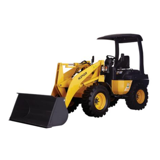
2 Components and safety labels 2. Components and Safety Labels 2.1 Components Operating lever ting cylinder Steering wheel pping cylinder of bucket Simple cover Engine hood Bucket leveler Intake of diesel Bucket Counterweight Rear wheel Hinged connection Front wheel Clearance position lamp Rocker Front lamp Moving arm... -
Page 12: Label
2 Components and safety labels 2.2 Label ◆There are many safety labels on the loader. Please read and understand them thoroughly before usage. Please read following information carefully. Keep away Sudden start Seized Away from moving arm and bucket Warning Read Instructions Lock for maintenance and transportation... - Page 13 2 Components and safety labels Warning Attention According to Rule for Labor Health, the Use special ISO VG32 brake loader and auxiliary components cannot be used for unintended purpose. oil but not common vegetable Read Instructions in advance and operate oil.
-
Page 14: Maintenance Of Safety Labels
2 Components and safety labels 2.3 Maintenance of safety labels 1) Keep the label clean. Do not contaminate or damage the label. If there is any dirt on the label, clean it with soapsuds and dry it with soft cloth. 2) If loader is washed with high-pressure water gun, label may fall off. -
Page 15: Operation Of Components
3 Operation of components 3. Operation of components 3.1 Safety components ▅Lock connection ▅ Start the engine at the neutral position It is used to lock the front and rear carriages to It is the safety component to avoid the sudden avoid unintended turning of them during check, start of loader when engine starts. -
Page 16: Name And Functionsof Components
3 Operation of components 3.2 Name and functions of components Horn button Steering wheel Button of turning lamp Instrument board Start key Operating lever of forward and backward Operating lever of bucket Brake pedal High/ low speed shift Lock button of operating lever of bucket Throttle pedal Pedal for stable movement... -
Page 17: Start Key (Stop With Start Lock)
3 Operation of components ▆ Start key (stop with start lock) Horn button ● OFF Operating lever Insert the start key and disconnect all electrical of forward and backward units at OFF. ● ON Turn the key to right from OFF to ON. Then all electrical circuits are energized. -
Page 18: Simple Measures
3 Operation of components ◆ Timer Indicator of jammed fuel filter Indicate the total runtime. It lights when start key is at ON. ◆ Rpm meter of engine It turns off when engine starts. Indicate the rpm of engine within one minute. Check the oil/water separator when ◆... -
Page 19: Switch Of Head Lamp
3 Operation of components ▆ Switch of head lamp ■ Brake pedal and pedal of stable movement If driver holds the switch of head lamp, head lamp, Hold the pedal to control the loader. As left and clearance position lamp and panel turn on. right pedals are linked, either of them can perform same control. -
Page 20: Lock Button Of Operating Lever Of Bucket
3 Operation of components ▆ Lock button of operating lever of bucket 3.4 Engine hood ON/OFF and driver’s seat It is used to lock the operating lever of bucket. ▆ Engine hood ON/OFF When operating lever of bucket is at the ◆Engine hood ON neutral position, press down the button Pull the operating lever upward and push the... -
Page 21: Operation Of Cab
3 Operation of components 3.5 Operation of cab 3. Work the fixed pull-rod to release the lock and ▆Door ON/OFF turn off the door. 1. Unlock the door with key and hold the handle 4. Lock the door if driver leaves the loader for a to open the door from outside. -
Page 22: Using And Adjusting Loader
4 Using and adjusting loader Chapter 4 Using and adjusting loader 4.1Running-in driving(operating new car) 4.4 Start when it is cold The new machine is delivered after fully adjusting 1. Fully step on the accelerator pedal. and checking, but the wrong operation method at 2. -
Page 23: Precautions After Operation In Low Temperature
4 Using and adjusting loader 1. Sharp drop or rise of the motor revolution. ● Table of the mixing percentage of water 2. Abnormal sound -10 -15 -20 -25 -30 -35 -40 and antifreeze 3. Abnormal exhaust color. Min. temperature(℃) 4. -
Page 24: Start, Drive And Stop
4 Using and adjusting loader 4.9 Start, drive and stop 3 For the steering wheel can not return ▆ Start automatically, the operation shall be completed 1. Adjust the lock bottom of the shovel handle bar manually. on [OPEN]. Important: 2. -
Page 25: Stop
4 Using and adjusting loader ◆ Note the allowable water depth ◆ Approaching the object During operation in water, after conforming the 1. Gunning the engine and stepping on the soft airproof of each plug and piston, use the machine moving pedal can approach the object. -
Page 26: Main Operation Using The Loader
4 Using and adjusting loader 4.11 Main operation using the loader Here, notice the basic operation using loader. In ■ Soil preparation addition, by using a variety of subsidiary 1. Turn and swing the shovel repeatedly, and then devices, open up new and practical operation. turn the shovel strictly. -
Page 27: Exhaust Of The Fuel System
4 Using and adjusting loader 4.12 Exhaust of the fuel system 5. If the bladder is exhausted, fasten the exhaust If the engine is running till the fuel runs out in the plug fully and install the cover. fuel tank, then do exhaust according to the 6. -
Page 28: Maintenance
5 Maintenance Chapter 5 Maintenance 5.1 Check * Before check or maintenance, put front and rear In order to use this machine safely and prevent operation rod at [Neutral position] and parking any troubles, please carry out frequent check and brake. -
Page 29: Check List Before Starting Up
5 Maintenance ■ Check list before starting up Feeding replacement of Referen Items Qty. grease ce page parts Any troubles at previous day. — - - Water or Check cooling water quantity in radiator and feed antifreeze ①Check engine oil level and feed Engine oil ②Check hydraulic oil level and feed Hydraulic oil... -
Page 30: Check And Filling Of Cooling Water
5 Maintenance ▆ Check and fill of engine oil ▆ Check and filling of cooling water 1. Check engine oil level to see if it reaches Spare tank is available on radiator for automatic regulated level. filling of cooling water in case of insufficiency. 2. -
Page 31: Check And Filling Of Hydraulic Oil
5 Maintenance leakage. Use brake fluid equivalent to hydraulic ■ Check and filling of hydraulic oil working oil ISO VG 32. General plant brake fluid 1. Park the vehicle at ground level and make sure is strictly forbidden. The oil level must be between the shovel contact with ground. -
Page 32: Grease Filling On Universal Joint
5 Maintenance ■ Grease filling on universal joint 3 points. Oil cup for steering pin Grease filling ■Check of tyre pressure, wearing, damage ■ Grease filling on center pin and loosened bolt Fill grease at center pin before working everyday. Refer to operation of tyre and check the tyre In case of insufficient grease, steering device (page 35). -
Page 33: Check And Cleaning Of Cooling Fan And Engine Oil Cooling Fan
5 Maintenance ■ Check and cleaning of cooling fan and 5.3 Precaution for vehicle washing engine oil cooling fan ■ Personal injury or mechanical damages and 1. Open engine cover. failure may be caused by improper use of high 2. Check for any block of fan. In case of block, pressure vehicle washer;... -
Page 34: List Of Period Check And Maintenance
5 Maintenance ■ List of period check and maintenance ○: Check and feeding, [Initial time]: first time replace, □: replace, (Initial time) : first time check, cleaning Equipment time (timer) From the Initial time date of purchase Once every Inspection items years Check batteries for charging ○... -
Page 35: Check And Maintenance Every50Hours
5 Maintenance 5.5 Check and maintenance every50hours ■ Water drainage of oil-water separator Located at upper left of rear support. Loosen ■ Battery check drainage nut in case of ponding; screw out 5mm 1. Open engine cover, and check display status and tighten it after drainage. -
Page 36: Check And Maintenance Every 200Hours
5 Maintenance ■ Cleaning and check off air filter element 5.6 Check and maintenance every 200hours Open engine cover, remove dust shield and take Carry following inspection out the element. Clean the element and dust maintenance every 50h. shield as well as internal surface of casing. ■... -
Page 37: Replacement Of Element Of Engine Oil Filter
5 Maintenance Drainage bolt Important * Check oil level after element replacement. In case of insufficient oil, fill in immediately. ■ Check and filling of oil in differential case at front and rear half shaft 1. Remove the plug and check engine oil level to see if it is filled near lower line of plug hole (hexed plug with subtense length of 10mm). -
Page 38: Replacement Of Element Of Oil Return Filter
5 Maintenance ■ Replacement of element of oil return filter The filter is installed at upper right of rear support. In case of temperature falling in working oil tank, remove the filter and replace element. Rear Drainage plug 3. Fill in gear oil to filling opening. Position Oil level Front... -
Page 39: Replacement Of Hydraulic Oil In Working Oil Tank
5 Maintenance 5.10 Maintenance every 1000 hours or one ■ Replacement of hydraulic oil in working oil year tank ■ Replacement of element of air filter (Replace it after 500h for initial use) Open engine cover, remove dust shield, loosen 1. -
Page 40: Using Method Of Antifreeze
5 Maintenance ■ Tyre pressure 4. Close thee plug and inject long-term coolant into radiator and spare case. Model KDD03 KDD05 KDD06 5. After injection of coolant, start up the engine and keep it racing for about 5min, and then stop Front 0.63±0.09Mpa... -
Page 41: Check And Use Of Batteries
5 Maintenance 5.14 Check and use of batteries ■ Precaution while battery charging Stop the engine first, put starting switch on [OFF] 1. Replace the battery in case of insufficient position and check battery, pay attention to: electrolyte. Battery this vehicle * Short circuit may occur while removing battery water-supplementing type. -
Page 42: Periodic Replacement Of Safety Parts
5 Maintenance 5.15 Periodic replacement of safety parts 5. Add antifreeze or drain out cooling water if the In order to ensure normal and safe operation, temperature is below 0 . ℃ operator shall carry out periodic inspection and 6. Start up engine and move the vehicle in a short maintenance, and also replacement of some distance, operate working device to make safety parts. -
Page 43: Reason And Solution
6. Reason and solution Chapter 6 Reason and solution ● Find the reason according to the following table if any failure occurs and solve it. ● If having any doubt, you can inquire the purchasing company or the fixed service company. 6.1 Engine failure Problem Reason... -
Page 44: Driving
6 Reason and resolution 6.2 Driving Problem Reason Solution Unsatisfied hydraulic system control valve performance Inquire the company selling the Unsatisfied electric switch of the forward product fixed service Driving in bad and backwards handle bar manner company. Unsatisfied following system cylinder of the (no moving when pump shifting speed)... -
Page 45: Hydraulic
6 Reason and resolution 6.3 Hydraulic Problem Reason Solution Broken pump coupling. Check and replace. Insufficient work oil. Add work oil Can not lift or Check the position where air vibrate the shovel Suck in air from the interface of suction pipe. enters and fasten the interface bolt or replace interface Insufficient function due to the wear and tear... -
Page 46: Pulling Method When Failure Occurs
6 Reason and solution 6.4 Pulling method when failure occurs Inquire the company selling the product or the fixed service company if the machine can not be started because of failure. At need, operate in the following order if the pulling is definitely necessary. -
Page 47: Attached Table
7 Attached table Chapter 7 Attached table 7.1 Main technology parameters Model KDD03 KDD05 KDD06 Type Tyre Swivel joint turning Operation weight (kg) 1300 2200 2850 Model KD373D KD388D Vertical, water-cooling, four Vertical, water-cooling, four Type strokes and direct injection... - Page 48 7Attached table Model KDD08 KDD10 Type Tyre Swivel joint turning Operation weight 2850 3800 (kg) Model KD488D KD488D Vertical, water-cooling, four Vertical, water-cooling, four strokes Type strokes and direct injection and direct injection Rated power/ rotation speed 26.2/2400 26.2/2400 /[kW/rpm] Max.
-
Page 49: Recommended Lubricate Oil, Lubricate And Fuel
7 Attached table 7.2 Recommended lubricate oil, lubricate and fuel Type of fuel, oil and grease, Supply position Common mark water Fuel tank Diesel oil -20#、-10#、0# Engine oil plate Engine oil 15W-40 Front half axis differential Gear oil 85W—90 gear box Back half axis differential gear box Gear oil... - Page 50 WWW.KIPOR.COM KIPOR Wuxi KIPOR Machinery Co., Ltd. Address: Beside Jingyi Rd, Third-stage Development Section of Wangzhuang Industry Area, Wuxi High & New Technology Industry Development Zone, Wuxi, Jiangsu, China Tel: 0510-85205100 85203799 Fax: 0510-85205026 85203795 EMAIL: kipor@kipor.com nxkipor@kipor.com...
Need help?
Do you have a question about the KDD03 and is the answer not in the manual?
Questions and answers