Table of Contents
Advertisement
Advertisement
Table of Contents

Subscribe to Our Youtube Channel
Related Manuals for HT MULTITEST M72


Summary of Contents for HT MULTITEST M72
- Page 1 ENGLISH User’s manual © Copyright HT ITALIA 2006 Release EN 2.00 - 22/08/2006...
-
Page 2: Table Of Contents
MULTITEST M72 - M73 - M74 - M75 SAFETY PRECAUTIONS AND PROCEDURES ....................... 2 1.1. Preliminary instructions ............................ 2 1.2. During use................................ 3 1.3. After use................................3 1.4. Overvoltage categories - definitions ......................... 3 GENERAL DESCRIPTION ............................4 2.1. Working ................................4 2.2. -
Page 3: Safety Precautions And Procedures
MULTITEST M72 - M73 - M74 - M75 1. SAFETY PRECAUTIONS AND PROCEDURES This instrument complies with safety Standards EN61557 and EN61010-1 related to electronic measuring instruments. CAUTION For your own safety and to avoid damaging the instrument follow the... -
Page 4: During Use
MULTITEST M72 - M73 - M74 - M75 1.2. DURING USE CAUTION An improper use may damage the instrument and/or its components or injure the operator. Before selecting any function, first disconnect the test leads from the circuit under test. -
Page 5: General Description
MULTITEST M72 - M73 - M74 - M75 2. GENERAL DESCRIPTION Dear Customer, the instrument you have purchased, whether used according to the instructions given in this manual, will grant you accurate and reliable measurements. Thanks to a development of newest conception assuring double insulation and overvoltage category III you will enjoy the highest safety. -
Page 6: Preparation For Use
MULTITEST M72 - M73 - M74 - M75 3. PREPARATION FOR USE 3.1. PRELIMINARY CHECKS This instrument was checked both mechanically and electrically prior to shipment. All possible cares and precautions were taken to let you receive the instrument in perfect conditions. -
Page 7: Operating Instructions
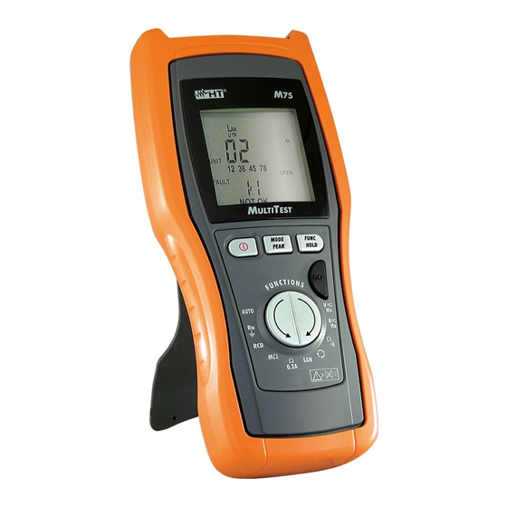
MULTITEST M72 - M73 - M74 - M75 4. OPERATING INSTRUCTIONS 4.1. INSTRUMENT - DESCRIPTION LEGEND: 1. Inputs 2. Display 3. ON/OFF key 4. MODE PEAK key 5. Arrows key 6. FUNC HOLD key 7. GO key 8. Remote units for LAN tests (M75 only) Fig. -
Page 8: Turning On
MULTITEST M72 - M73 - M74 - M75 4.1.1. Turning on When the instrument is turned on, it emits a brief sound and all display segments are lit for just one second. Then the model number and the firmware release appear on the display (see picture referred to M75). -
Page 9: Hold, Max/Min/Avg, Peak
MULTITEST M72 - M73 - M74 - M75 4.2. HOLD, MAX/MIN/AVG, PEAK± The following functions are available for measurements of AC and DC voltage, AC current, frequency and resistance. 4.2.1. HOLD The HOLD function permits to block on the display the detected value during measurements of AC and DC voltage, AC current, frequency and resistance. -
Page 10: Hz: Dc/Ac Voltage And Frequency Measurement (M73 And M75)
MULTITEST M72 - M73 - M74 - M75 4.3. Hz: DC/AC VOLTAGE AND FREQUENCY MEASUREMENT (M73 AND M75) CAUTION The maximum input voltage is 550+10%V. Don’t try to measure higher voltages to avoid risks of electrical shocks or serious damages to the instrument. -
Page 11: Frequency Measurement
MULTITEST M72 - M73 - M74 - M75 Example of display of DC voltage. The DC voltage value minimum reading limit of DC voltage is 1.2V. Lower input values are displayed as 0.0V. MODE Press MODE PEAK for less than 1 second to pass to frequency PEAK measurement (only during AC measurements, see paragraph 4.3.1) -
Page 12: Anomalous Cases Which May Occur During
MULTITEST M72 - M73 - M74 - M75 4.3.2. Anomalous cases which may occur during V Hz measurements 1. The maximum input voltage 550+10%V. If the detected voltage value exceeds 605V TRMS the instrument displays the screen beside. Disconnect immediately the instrument... -
Page 13: A Hz: Dc/Ac Current And Frequency Measurement
MULTITEST M72 - M73 - M74 - M75 4.4. Hz: DC/AC CURRENT AND FREQUENCY MEASUREMENT Fig. 3: Connection of the instrument’s terminals during A Hz test Turn on the instrument Press the arrow keys to select A Insert the banana connectors of the clamp transducer in the corresponding input terminals of the instrument (black with black, green or red with green) Make sure that the clamp full scale and the instrument full scale do correspond. -
Page 14: Frequency Measurement
MULTITEST M72 - M73 - M74 - M75 Example of AC current displaying. The AC current value minimum limit of AC current is: 1.0mV x transduction ratio of the clamp lower values are nullified. Frequency value The minimum reading value of AC and DC current is given by the herewith: 1mV x transduction ratio of the clamp Therefore, with a clamp 400A/400mV, the minimum measurable current is 1.0A. -
Page 15: Anomalous Cases Which May Occur During A Hz Measurements
MULTITEST M72 - M73 - M74 - M75 4.4.2. Anomalous cases which may occur during A Hz measurements If the detected current value exceeds the Example of clamp full clamp full scale the instrument displays scale set at 400A AC the screen beside. -
Page 16: Ω : Resistance Measurement And Continuity Test
MULTITEST M72 - M73 - M74 - M75 Ω : 4.5. RESISTANCE MEASUREMENT AND CONTINUITY TEST CAUTION Before taking resistance measurements make sure that the circuit under test is not powered and that eventual condensers are discharged. Fig. 4: Connection of the instrument’s terminals during Ω... -
Page 17: Anomalous Cases Which May Occur During Ω Measurement
MULTITEST M72 - M73 - M74 - M75 Fig. 5: Connection of the instrument’s terminals during calibration procedure Press MODE PEAK for more than 1 second. The instrument resets the MODE resistance of the cables, the symbol " " is displayed... -
Page 18: Phase Sequence And Conformity Measurement
MULTITEST M72 - M73 - M74 - M75 4.6. PHASE SEQUENCE AND CONFORMITY MEASUREMENT CAUTION The maximum input voltage is 550+10%V. Don’t try to measure higher voltages to avoid risks of electrical shocks or serious damages to the instrument. Do not use the instrument on plants whose interlinked rated voltage is higher than 550V. - Page 19 MULTITEST M72 - M73 - M74 - M75 CAUTION For a correct functioning of mode 1W it’s necessary that the star centre of the three-phase triad under test is at the earth potential. In plants with insulated neutral wire, like IT systems (often present in hospitals, airports etc.) it’s necessary to select mode 2W and connect the green probe to...
- Page 20 MULTITEST M72 - M73 - M74 - M75 CAUTION During measurement: • GO must be always kept pressed or its surface must be always touched (only for mode 1W) • the test probe, except for the phase cable under test, must not be in touch or close to any voltage source which may block the measurement due to the instrument’s sensitivity...
-
Page 21: Anomalous Cases Which May Occur During Tests
MULTITEST M72 - M73 - M74 - M75 4.6.1. Anomalous cases which may occur during tests 1. If you wait more than 10 seconds between the first measurement and the second one, the instrument emits a prolonged sound to signal the negative outcome of the test and displays a screen like this. -
Page 22: Lan: Cabling Test (M75)
MULTITEST M72 - M73 - M74 - M75 4.7. LAN: CABLING TEST (M75) CAUTION Before taking any measurement make sure that the circuit under test is not powered. Connections to phone lines or active networks could damage the instrument. Fig. 7: Connections of the instrument’s terminals during LAN tests... -
Page 23: Anomalous Cases Which May Occur During Lan Tests
MULTITEST M72 - M73 - M74 - M75 If cabling is not correct, a screen like this Identification number of the remote unit (if is displayed (NOT OK). Referring to this possible to find it) example, “FAULT 1/4” means that the detected errors are 4, of which the first one is currently displayed. -
Page 24: Cabling Errors
MULTITEST M72 - M73 - M74 - M75 4.7.3. Cabling errors Cabling errors Description Visualization Mapping One or both conductors OPEN PAIR of the pair are interrupted (open) The conductors of the REVERSED PAIR same pair are reversed Two conductors are in... -
Page 25: Ω 0.2A: Continuity Test On Earth, Protective And Equalizing Potential Conductors (M72, M74, M75)
MULTITEST M72 - M73 - M74 - M75 Ω 0.2A: CONTINUITY TEST ON EARTH, PROTECTIVE AND EQUALIZING 4.8. POTENTIAL CONDUCTORS (M72, M74, M75) The measurement is performed with a test current higher than 200 mA (R<5Ω) and open circuit voltage ranging from 4 to 24V DC according to EN 61557-2 and VDE 0413 part 4. -
Page 26: Cal" Mode
MULTITEST M72 - M73 - M74 - M75 CAUTION The message “Measuring” on the display means that the instrument is measuring. During this phase never disconnect test leads. Connect the instrument just BEFORE measuring and do not change connections while the message “Measuring”... - Page 27 MULTITEST M72 - M73 - M74 - M75 MODE By pressing MODE select CAL PEAK 2. Any addition or replacement of cables, extensions and croco clips nullify the previous calibration and make necessary a new calibration before performing further measurements. Therefore the instrument must be calibrated in the same conditions at which it will operate during measurements 3.
-
Page 28: Anomalous Cases Which May Occur During Ω 0.2A Tests
MULTITEST M72 - M73 - M74 - M75 4.8.2. Anomalous cases which may occur during Ω 0.2A tests 1. If the following condition occur: < -0.02Ω MEASURED CALIBRATION the instrument displays the screen beside and emits a prolonged sound to signal the anomalous situation 2. -
Page 29: Mω: Insulation Resistance Measurement Test Voltage 500V
MULTITEST M72 - M73 - M74 - M75 4.9. MΩ: INSULATION RESISTANCE MEASUREMENT TEST VOLTAGE 500V The measurement is performed according to EN 61557-2 and VDE 0413 part 1. CAUTION • before performing the insulation test make sure that the circuit under test is not energized and all relative loads are disconnected •... -
Page 30: Anomalous Cases Which May Occur During Mω Tests
MULTITEST M72 - M73 - M74 - M75 CAUTION The message “Measuring” on the display means that the instrument is measuring or discharging eventual capacitors. During this phase never disconnect nor touch test leads. At the end of the test, before giving the result of the measurement, the instrument... -
Page 31: Rcd: Tests On Ac Type Rcds (M73, M74, M75)
MULTITEST M72 - M73 - M74 - M75 4.10. RCD: TESTS ON AC TYPE RCDS (M73, M74, M75) The test is performed in compliance with CEI 64.8 612.9, CEI 64.8/6 appendix D, EN61008, EN61009, EN 60947-2 part B 4.2.4.1 and VDE 0413 part 6. -
Page 32: Anomalous Cases Which May Occur During Rcd Tests
MULTITEST M72 - M73 - M74 - M75 Keep GO pressed for at least one second to perform the leakage current measurement in phase with the positive semiwave of the network voltage (0°), or keep GO pressed for at least one second and, when the hyphens on the... - Page 33 MULTITEST M72 - M73 - M74 - M75 2. If during measurement a lower input voltage than 110V is detected, the instrument does not perform the test and emits a prolonged sound to signal the anomalous situation. The screen beside...
-
Page 34: Ra : Measurement Of Global Earth Resistance (M73, M74, M75)
MULTITEST M72 - M73 - M74 - M75 4.11. RA MEASUREMENT OF GLOBAL EARTH RESISTANCE (M73, M74, M75) CAUTION Disconnect all loads connected to the lower end of the RCD as they could introduce additional leakage currents, thus nullifying the test results. Is possible to perform measurement on plants whose phase to earth rated voltage is up to 265V. - Page 35 MULTITEST M72 - M73 - M74 - M75 Insert the Shuko cable in the input terminals of the instruments Insert the Shuko cable in a power socket (as shown in Fig. 12). The picture represents the connection to power socket...
-
Page 36: Anomalous Cases Which May Occur During Ra Tests
MULTITEST M72 - M73 - M74 - M75 4.11.1. Anomalous cases which may occur during Ra tests 1. If during measurement protecting the line trips, the instrument interrupts the test and emits a prolonged sound to signal the anomalous situation. - Page 37 MULTITEST M72 - M73 - M74 - M75 5. If during measurement the green probe is connected to the phase conductor and the black probe is connected to the protective conductor, the instrument does not perform the test and emits a prolonged sound to signal the anomalous situation.
-
Page 38: Auto: Automatic Cycle Of Measurements To Test A Plant (M74, M75)
MULTITEST M72 - M73 - M74 - M75 4.12. AUTO: AUTOMATIC CYCLE OF MEASUREMENTS TO TEST A PLANT (M74, M75) This function permits to test an electrical plant in a completely automatic way without any intervention of the operator. CAUTION Testing an RCD involves the tripping of the RCD itself. - Page 39 MULTITEST M72 - M73 - M74 - M75 CAUTION The message “Measuring” on the display means that the instrument is measuring. During this phase never disconnect test leads. During measurements, at the end of each test, the partial values are displayed for 5...
-
Page 40: Maintenance
MULTITEST M72 - M73 - M74 - M75 5. MAINTENANCE 5.1. GENERAL This is a precision instrument. Strictly follow the instructions for use and storage reported in this manual to avoid any possible damage or danger during use. Do not use this tester under unfavorable conditions of high temperature or humidity. Do not expose to direct sunlight. -
Page 41: Technical Specifications
MULTITEST M72 - M73 - M74 - M75 6. TECHNICAL SPECIFICATIONS This product conforms to the prescriptions of the European directive on low voltage 73/23/EEC (LVD) and to EMC directive 89/336/EEC, amended by 93/68/EEC. 6.1. CHARACTERISTICS Accuracy is indicated as [% of reading + digit number]. It is referred to the following reference conditions: 23°C ±... - Page 42 MULTITEST M72 - M73 - M74 - M75 Phase sequence and phase conformity Measuring method Working voltage (V) System up to 315 V (Phase - Ground) 90 ÷ 315 (Phase - Ground) 1 test lead (1W) up to 550V (Phase - Phase) up to 315 V (Phase - Neutral) 90 ÷...
-
Page 43: Electrical
MULTITEST M72 - M73 - M74 - M75 6.1.1. Electrical Conversion: ADC 16 bit, TRMS – True Root Mean Square Measuring rate: 64 times per second Display refreshing rate: 2 times per second 6.1.2. Safety standards The instrument complies with:... -
Page 44: Service
MULTITEST M72 - M73 - M74 - M75 7. SERVICE 7.1. WARRANTY CONDITIONS This instrument is guaranteed against material or production defects, in accordance with our general sales conditions. During the warranty period the manufacturer reserves the right to decide either to repair or replace the product.
Need help?
Do you have a question about the MULTITEST M72 and is the answer not in the manual?
Questions and answers