Table of Contents
Advertisement
Quick Links
Advertisement
Table of Contents

Subscribe to Our Youtube Channel
Related Manuals for HT Neptune


Summary of Contents for HT Neptune
- Page 1 ENGLISH User manual Copyright HT ITALIA 2018 Release EN 1.00 - 31/10/2018...
-
Page 3: Table Of Contents
NEPTUNE TABLE OF CONTENTS PRECAUTIONS AND SAFETY MEASURES ............... 2 1.1. Preliminary instructions ..................... 2 1.2. During use ......................... 3 1.3. After use ..........................3 1.4. Definition of Measurement (Overvoltage) category ............3 GENERAL DESCRIPTION ................... 4 ... -
Page 4: Precautions And Safety Measures
Only the leads supplied with the instrument guarantee compliance with the safety standards. They must be in good conditions. If necessary, only replace them with original HT accessories. Do not test circuits exceeding the specified voltage limits. Do not perform any test under environmental conditions exceeding the limits indicated in §... -
Page 5: During Use
NEPTUNE 1.2. DURING USE Please carefully read the following recommendations and instructions: CAUTION Failure to comply with the caution notes and/or instructions may damage the instrument and/or its components or be a source of danger for the operator. Before activating the rotary switch, disconnect the test leads from the circuit being measured. -
Page 6: General Description
NEPTUNE 2. GENERAL DESCRIPTION The instrument carries out the following measurements: DC / AC, AC+DC TRMS voltage DC / AC / AC+DC TRMS voltage with low impedance (LoZ) DC / AC / AC+DC TRMS current with standard clamp transducer ... -
Page 7: Preparation For Use
NEPTUNE 3. PREPARATION FOR USE 3.1. INITIAL CHECKS Before shipping, the instrument has been checked from an electric as well as mechanical point of view. All possible precautions have been taken so that the instrument is delivered undamaged. However, we recommend generally checking the instrument in order to detect possible damage suffered during transport. -
Page 8: Nomenclature
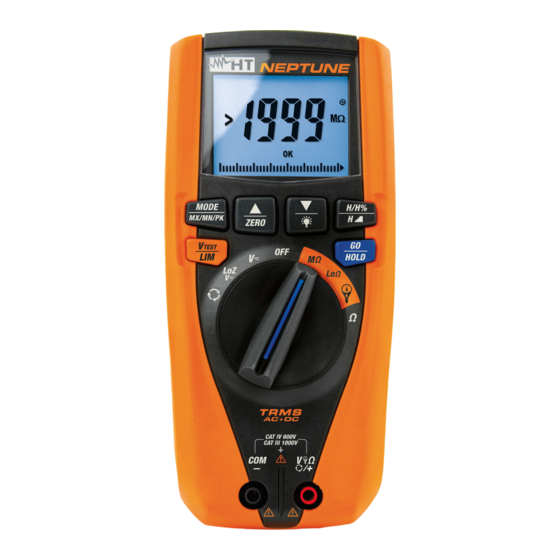
NEPTUNE 4. NOMENCLATURE 4.1. DESCRIPTION OF THE INSTRUMENT CAPTION: 1. LCD display 2. Key / ZERO 3. Key/ 4. Key MODE/MXMNPK 5. Key H/H%/H 6. Key V /LIM TEST 7. Key GO/HOLD 8. Rotary selector switch 9. Input terminal COM/... -
Page 9: Description Of Function Keys
NEPTUNE 4.2. DESCRIPTION OF FUNCTION KEYS 4.2.1. Key GO/HOLD , and Pressing the key GO/HOLD (for functions V , LoZV ) makes the instrument hold the value of the quantity shown on the display. The message HOLD appears on the “... -
Page 10: Key Mode/Mxmnpk
NEPTUNE 4.2.3. Key MODE/MXMNPK A simple pressing of key MODE/MXMNPK allows for the following operations: Selection of measuring modes AUTO AC+DC FREQ in positions “ ” “ ” “ ” “ ” “ ” , LoZV Selection of measuring modes... -
Page 11: Loz Function
NEPTUNE 4.2.6. LoZ function This mode allows carrying out AC/DC voltage measurement with a low input impedance, in order to eliminate wrong readings due to parasite voltages for capacitive couplings. CAUTION By plugging the instrument between the phase and earth conductor, because of the low impedance of the instrument during measurement, RCD protections may trip while carrying out the test. -
Page 12: Setting The Full Scale For Flexible Clamp Transducer
NEPTUNE 4.2.10. Setting the full scale for flexible clamp transducer The instrument can be used with a flexible clamp transducer (optional accessory). For a correct current measurement, it is necessary to set the full scale of voltage for the clamp... -
Page 13: Operating Instructions
NEPTUNE 5. OPERATING INSTRUCTIONS 5.1. DC VOLTAGE MEASUREMENT CAUTION The maximum input DC voltage is 1000V. Do not measure voltages exceeding the limits given in this manual. Exceeding voltage limits could result in electrical shocks to the user and damage to the instrument. -
Page 14: Ac, Ac+Dc Voltage Measurement
NEPTUNE 5.2. AC, AC+DC VOLTAGE MEASUREMENT CAUTION The maximum input AC voltage is 1000V to earth. Do not measure voltages exceeding the limits given in this manual. Exceeding voltage limits could result in electrical shocks to the user and damage to the instrument. -
Page 15: Ac, Dc, Ac+Dc Voltage With Low Impedance (Loz)
NEPTUNE 5.3. AC, DC, AC+DC VOLTAGE WITH LOW IMPEDANCE (LOZ) CAUTION The maximum input AC/DC voltage is 1000V to earth. Do not measure voltages exceeding the limits given in this manual. Exceeding voltage limits could result in electrical shocks to the user and damage to the instrument. -
Page 16: Resistance Measurement And Continuity Test
NEPTUNE 5.4. RESISTANCE MEASUREMENT AND CONTINUITY TEST CAUTION Before attempting any resistance measurement, cut off power supply from the circuit to be measured and make sure that all capacitors are discharged, if present. Fig. 9: Use of the instrument for resistance measurement and continuity test 1. -
Page 17: Phase Sequence And Phase Concordance With 1 Terminal
NEPTUNE 5.5. PHASE SEQUENCE AND PHASE CONCORDANCE WITH 1 TERMINAL CAUTION Input AC voltage to carry out this test must be in range 100V ÷ 1000V with a frequency in range 42.5Hz ÷ 69Hz. This test can only be performed by touching the metal parts of the conductors. - Page 18 NEPTUNE 4. In conditions of correct voltage and frequency, the instrument shows message HOLD “ ” symbols and the buzzer sounds continuously, waiting for a stable voltage “ ” value on phase L1 to be detected (see Fig. 12 left side).
-
Page 19: Measurement Of Insulation Resistance
NEPTUNE 5.6. MEASUREMENT OF INSULATION RESISTANCE This function is performed in compliance with standard IEC/EN61557-2 and allows measuring insulation resistance in electric installations and industrial applications where it is necessary to carry out duration tests (see § 9.2). The following operating modes are available: ... - Page 20 NEPTUNE 5. Press keys / or /ZERO to select the value among the options: 0.10M, 0.230M, 0.50M, 1.00M, 100M, no. Option indicates that no threshold was “ ” set (see Fig. 16). Fig. 16: Setting the limit threshold for insulation measurement 6.
- Page 21 NEPTUNE TMR mode CAUTION Check that the circuit being tested is not live and that all possible loads normally connected to it are disconnected before carrying out insulation measurement. We recommend holding the alligator clip respecting the safety area created by the hand protection.
- Page 22 NEPTUNE 6. Insert the red lead into input terminal V /+ and the black lead into input terminal COM/ and possible alligator clips, and connect the instrument to the system to be tested (see Fig. 19). 7. Press key GO/HOLD to activate the test. The screen in Fig. 17 may appear on the display to signal the presence of a voltage >10V found on the input terminals,...
- Page 23 NEPTUNE Fig. 22: Use of the instrument for insulation resistance measurement in PI mode 1. Select position M 2. Press key MODE/MXMNPK and select option “ ” 3. Press key V /LIM to set the test voltage choosing among the values: 50V, 100V, TEST 250V, 500V, 1000VDC.
- Page 24 NEPTUNE 9. In the screen in Fig. 23 left side, the value of insulation resistance is present at the – end of measurement with positive result (value higher than the set threshold). In “ ” the screen in Fig. 23 right side, the value of insulation resistance is present at the end –...
-
Page 25: Continuity Of Protective Conductors With 200Ma
NEPTUNE 5.7. CONTINUITY OF PROTECTIVE CONDUCTORS WITH 200MA This function is performed in compliance with standard IEC/EN61557-4 and allows measuring the continuity of protective and equipotential conductors. The following operating modes are available: AUTO the test is activated by pressing key GO/HOLD and the result is immediately displayed after comparing it with the set maximum threshold value. - Page 26 NEPTUNE 1. Select position Lo 2. Press key MODE/MXMNPK and select option AUTO “ ” 3. Press and hold key V /LIM (>2s) to set the maximum limit threshold for TEST measurement. The symbol flashes on the display. “...
- Page 27 NEPTUNE TMR mode CAUTION Check that the circuit being tested is not live and that all possible loads normally connected to it are disconnected before carrying out insulation measurement. The continuity test is performed by supplying a current higher than 200mA for resistances not higher than 5 ...
- Page 28 NEPTUNE 6. If necessary, compensate the test cables (see § 5.7.1). 7. Insert the red lead into input terminal V /+ and the black lead into input terminal COM/ , and connect the instrument to the system to be tested (see Fig. 29).
-
Page 29: Function Zero - Zeroing Of Test Cable Resistance
NEPTUNE 5.7.1. Function ZERO Zeroing of test cable resistance – In every operating mode (AUTO, TMR) it is possible to zero the resistance of the test cables before carrying out continuity tests. This operation is recommended upon the first use of the provided test cables and in case different cables must be used (e.g. cable extensions). - Page 30 NEPTUNE measurement and comparing this new value to the compensated one. If the difference 0.01 , calibration is confirmed and the message between the values is ≤ “ ” displayed (see Fig. 33 middle). Subsequently, the instrument goes back to the –...
-
Page 31: Measurement Of Dc, Ac, Ac+Dc, Inrush Current With Clamp Transducers
The instrument carries out the measurement both with flexible clamp transducers (optional accessories) and with other standard clamp transducers in the HT family (optional accessories). With transducers having an Hypertac output connector, the optional adapter NOCANBA is necessary to obtain the connection. - Page 32 NEPTUNE 6. For standard clamp transducers, press key MODE/MXMNPK to select “ ” “ ” AC+DC measurement. Anyway, the instrument automatically recognizes AC or DC “ ” quantities. 7. Insert the red cable into input terminal V /+ and the black cable into input terminal COM/ ...
- Page 33 The instrument carries out the measurement both with flexible clamp transducers (optional accessories) and with other standard clamp transducers in the HT family (optional accessories). For inrush currents containing a high DC component, the use of AC/DC clamps is recommended.
- Page 34 NEPTUNE 9. Upon recognition of the event, measurement stops automatically and the instrument shows, in its main display, the Max RMS value calculated according to the evaluation time of 100ms (default) indicated on the secondary display (see Fig. 41 right side).
-
Page 35: Maintenance
NEPTUNE 6. MAINTENANCE CAUTION Only expert and trained technicians should perform maintenance operations. Before carrying out maintenance operations, disconnect all cables from the input terminals. Do not use the instrument in environments with high humidity levels or high temperatures. Do not expose to direct sunlight. -
Page 36: Technical Specifications
NEPTUNE 7. TECHNICAL SPECIFICATIONS 7.1. TECHNICAL CHARACTERISTICS Accuracy calculated as [%reading + (no. digits*resolution)] at 23°C 5°C <80%RH. DC Voltage (Autorange) Range Resolution Input Accuracy Overload protection impedance 0.0 999.9 (0.5%rdg + 2digits) 5M 1000VDC/ACrms AC, AC+DC, Loz TRMS Voltage (Autorange) - Page 37 NEPTUNE Harmonic voltage and current (Autorange) Fundamental Accuracy (*) Harmonic order Resolution frequency (non-zeroed values) (5.0rdg+20digits) 0.1V / 0.1A /0.1% 1 25 42.5Hz 69Hz (5.0rdg+10digits) (10.0rdg+10digits) THD% 0.1% ’ Accuracy of harmonic amplitudes expressed in % is evaluated considering the accuracy of parameters...
-
Page 38: General Characteristics
NEPTUNE Reference guidelines Instrument safety: IEC/EN61010-1,IEC/EN61010-2-030, IEC/EN61010-2-033 EMC: IEC/EN 61326-1 M test: IEC/EN 61557-2 Lo test: IEC/EN 61557-4 Phase sequence: IEC/EN 61557-7 Insulation: double insulation Pollution level: Measurement category: CAT IV 600V, CAT III 1000V to earth and between inputs 7.1.1. -
Page 39: Assistance
NEPTUNE 8. ASSISTANCE 8.1. WARRANTY CONDITIONS This instrument is warranted against any material or manufacturing defect, in compliance with the general sales conditions. During the warranty period, defective parts may be replaced. However, the manufacturer reserves the right to repair or replace the product. -
Page 40: Theoretical
NEPTUNE 9. THEORETICAL APPENDIXES 9.1. CONTINUITY OF PROTECTIVE CONDUCTORS Purpose of the test Checking the continuity of: Protective conductors (PE), main equalizing potential conductors (EQP), secondary equalizing potential conductors (EQS) in TT and TN-S systems. Neutral conductors having functions of protective conductors (PEN) in TN-C systems. -
Page 41: Measurement Of Insulation Resistance
NEPTUNE 9.2. MEASUREMENT OF INSULATION RESISTANCE Purpose of the test Check that the insulation resistance of the installation complies with the requirements of the applicable standard. This test has to be performed with the circuit being tested not powered and with the possible loads it supplies disconnected. - Page 42 NEPTUNE EXAMPLE OF HOW TO MEASURE THE INSULATION OF A SYSTEM Fig. 45: Example of an electric system Switches D and E are the switches installed near the load which have the function of separating the load from the system. Should these switches not be provided, or should they be single-pole switches, it is necessary to disconnect the users from the system before performing the insulation resistance test.
- Page 43 NEPTUNE Spot where to Measureme Switch conditions perform System evaluation measurement If RR OK (end of test) Open switches A, D LIMITE On switch A and E Proceed to 2 If RR LIMITE Proceed to 3 If RR LIMITE ...
-
Page 44: Polarization Index (Pi)
NEPTUNE 9.2.1. Polarization Index (PI) The purpose of this diagnostic test is to evaluate the influence of the polarization effects. Upon the application of a high voltage to insulation, the electric dipoles distributed in the insulation align in the direction of the applied electric field. This phenomenon is called polarization. -
Page 45: Voltage And Current Harmonics
NEPTUNE 9.3. VOLTAGE AND CURRENT HARMONICS Any periodic non-sinusoidal wave may be represented by a sum of sinusoidal waves, each with a frequency which is a whole multiple of the fundamental, according to the relationship: ... - Page 46 NEPTUNE Odd Harmonics Even Harmonics Not multiple of 3 Multiple of 3 Relative Voltage Order h Relative Voltage Relative Voltage Order h Order h %Max %Max %Max 6..24 Table 4: Limits for the harmonic voltages the supplier may introduce into the network.
Need help?
Do you have a question about the Neptune and is the answer not in the manual?
Questions and answers