
Subscribe to Our Youtube Channel
Summary of Contents for Zircon EN54
- Page 1 EN54 & ISO 7240 2- 8 Zone Conventional Fire Control Panel Installation, Commissioning & Configuration Manual 997-532-000-1, Issue 1.0 For use with Zircon EN 2-8 Fire Control Panels...
-
Page 2: Table Of Contents
EN54 & ISO 7240 2-8 Zone Conventional Fire Panel - Installation & Configuration Manual The following markings are used either on Contents the panel hardware or in the documentation. They have the following meaning: Introduction WARNING: Risk of electric shock. - Page 3 EN54 & ISO 7240 2-8 Zone Conventional Fire Panel - Installation & Configuration Manual 6.3.3 Sounder Circuits ........16 6.3.4 2-Way Relay PCB (Optional) ....16 6.3.5 8-Way Relay PCB (Optional) ....16 Powering the Panel ........17 6.4.1 Standby Batteries ........17 Configuration and Handover ......
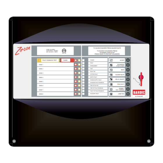
- Page 4 Zircon EN54 2-8 Zone Fire Control Panel TO SILENCE BUZZER PRESS BUZZER MUTE FIRE ALARM CONTROL PANEL TO SILENCE SOUNDERS PRESS EN 54-2/4 1997 SOUNDER START/STOP 154d / 154f PRESS AGAIN TO RESTART SOUNDERS FAULT/ DISABLED/ TEST ALARM POWER ACCEPT...
-
Page 5: Introduction Manual Purpose
EN54 & ISO 7240 2-8 Zone Conventional Fire Panel - Installation & Configuration Manual Introduction 1.1 Manual Purpose The purpose of this manual is to provide the user with all recommended procedures and full technical details for the successful installation, commissioning and configuration of the EN54 (and ISO 7240) 2-8 Zone Conventional Fire Control Panel. -
Page 6: Ce Marking
EN54 & ISO 7240 2-8 Zone Conventional Fire Panel - Installation & Configuration Manual The panel can accept an unlimited number of manual call points and a limited number of automatic detectors per zone. Refer to Section 8 Specification for zone current limits. -
Page 7: En54 & Iso 7240 Functions
EN54 & ISO 7240 2-8 Zone Conventional Fire Panel - Installation & Configuration Manual 1.5 EN54 & ISO 7240 Functions This fire control panel is designed to comply with the requirements of EN54 Part 2/4 and ISO 7240 Part 2/4. -
Page 8: Ancillary Functions
EN54 & ISO 7240 2-8 Zone Conventional Fire Panel - Installation & Configuration Manual 1.6 Ancillary Functions The following is a list of ancillary functions that are provided by the control panel in addition to those required by EN54-2/4. These functions are described in the section of this manual as referenced. -
Page 9: Installation Guide
EN54 & ISO 7240 2-8 Zone Conventional Fire Panel - Installation & Configuration Manual Installation Guide 2.1 How to Use this Guide This Installation Guide provides you with simple guidelines to install a fire control panel system, quickly and safely. The guide does not describe panel configuration procedures as it is covered by the relevant section of this manual. -
Page 10: Transient Protection
EN54 & ISO 7240 2-8 Zone Conventional Fire Panel - Installation & Configuration Manual e) DO NOT locate the panel where there are high levels of vibration or shock f) DO NOT site the panel where there would be restricted access to the internal equipment and cabling/wiring connections. -
Page 11: Product Inspection
EN54 & ISO 7240 2-8 Zone Conventional Fire Panel - Installation & Configuration Manual 2.4 Product Inspection The Zircon EN 2-8 Zone Fire control panel is simple to Check for damage install and commission if the recommended procedures described in this Installation Guide, and the Installation before proceeding with and Commissioning sections of this manual, are followed. -
Page 12: Installation Preparation
EN54 & ISO 7240 2-8 Zone Conventional Fire Panel - Installation & Configuration Manual 2.5 Installation Preparation This section describes making the panel ready for installation. 2.5.1 Removing the Cover Remove the front cover as follows: Use the supplied 4mm hexagonal socket wrench to release the two recessed, socket-headed screws located in position ‘A’... -
Page 13: Optional Equipment
EN54 & ISO 7240 2-8 Zone Conventional Fire Panel - Installation & Configuration Manual 2.6 Optional Equipment 2.6.1 2-Way Relay PCB (ZIRCON/EN/FFR) An optional PCB supporting Fire and Fault condition, volt- free, status outputs may be fitted. When fitted, the PCB is connected to the Main PCB via connector, PL1. -
Page 14: Cabling Instructions
EN54 & ISO 7240 2-8 Zone Conventional Fire Panel - Installation & Configuration Manual Cabling Cabling Instructions All wiring should comply with current IEE wiring WARNING Risk of electric regulations (BS7671) or the applicable local wiring shock. Before working on regulations. -
Page 15: Cable Terminations
EN54 & ISO 7240 2-8 Zone Conventional Fire Panel - Installation & Configuration Manual 3.1.1 Cable Terminations This section provides guidance on where to bring cables into the back box for ease of termination. a. The mains supply should be brought into the control... -
Page 16: Emc Considerations
EN54 & ISO 7240 2-8 Zone Conventional Fire Panel - Installation & Configuration Manual EMC Considerations Following the above instructions and by using suitable screened cables EMC problems will be avoided. In particularly difficult EMC environments, or where non- preferred cabling is used, it is possible to fit ferrite sleeves to cables entering the panel, in particular the power supply input, sounder and auxiliary output cables. -
Page 17: Field Devices
EN54 & ISO 7240 2-8 Zone Conventional Fire Panel - Installation & Configuration Manual Field Devices The Fire Control Panel is capable of working with various manucturer’s field devices (for compatible field devices refer to Section 1 Introduction). Each of these devices is supplied with an instruction leaflet showing the correct interconnections for various applications. -
Page 18: Panel Electronics
EN54 & ISO 7240 2-8 Zone Conventional Fire Panel - Installation & Configuration Manual Panel Electronics The Fire Control Panel is supplied with the following factory-fitted electronic equipment: • Main PCB • PSU PCB These PCBs do not need to be removed to install the back box. -
Page 19: Psu Pcb
EN54 & ISO 7240 2-8 Zone Conventional Fire Panel - Installation & Configuration Manual Refitting the Main PCB The procedure for refitting the Main PCB is the reverse of the removal procedure but note the following points: When offering the Main PCB to the three locating tabs... -
Page 20: Commissioning Introduction
EN54 & ISO 7240 2-8 Zone Conventional Fire Panel - Installation & Configuration Manual Commissioning 6.1 Introduction It is recommended that the control panel is powered up and tested before connecting the field devices. 6.2 Preliminary Checks Before connecting the mains power to the panel, check: 1 The earth lead from the safety earth post is connected to the earth tag on the Main PCB. -
Page 21: Powering The Panel
EN54 & ISO 7240 2-8 Zone Conventional Fire Panel - Installation & Configuration Manual 6.4 Powering the Panel Before applying mains power to the control panel make sure that you carry out the following checks and procedures: 1 Check that you carried out all the instructions described in Section 6.2 Preliminary Checks. - Page 22 EN54 & ISO 7240 2-8 Zone Conventional Fire Panel - Installation & Configuration Manual An air gap of at least 10mm should be maintained between the batteries to assist cooling. 2 Connect the batteries using the provided items: a. Red battery lead (1 off) b.
- Page 23 EN54 & ISO 7240 2-8 Zone Conventional Fire Panel - Installation & Configuration Manual Recommended Battery Size The recommended battery sizes are given in the table below. The table is in two parts: the top part recommends battery sizes when 0.47μF capacitor EOL devices are used with 2, 4 or 8 zone panels and with 24hr or 72hr battery backup.
-
Page 24: Configuration And Handover
EN54 & ISO 7240 2-8 Zone Conventional Fire Panel - Installation & Configuration Manual 6.5 Configuration and Handover After all external wiring has been connected to the panel CAUTION - Heat Hazard! and with no faults existing, the panel can be configured Under certain fault conditions for the particular system requirements. - Page 25 EN54 & ISO 7240 2-8 Zone Conventional Fire Panel - Installation & Configuration Manual Method 2: Supports new and existing installations using Active End- of-Line (AEOL) - (ZIRCON/EN/CAPKIT). For the AEOL to function correctly an additional 10µF stabilising capacitor must be fitted across the zone terminals (not supplied).
-
Page 26: Sounder Circuits
EN54 & ISO 7240 2-8 Zone Conventional Fire Panel - Installation & Configuration Manual 6.8 Sounder Circuits Two sounder output circuits are provided. The termination block, TB1, for the sounder circuits is located at the top left-hand corner of the PSU PCB. -
Page 27: Digital Inputs
EN54 & ISO 7240 2-8 Zone Conventional Fire Panel - Installation & Configuration Manual 6.9 Digital Inputs Two digital input circuits are provided. Terminal block, TB5, is provided on the Main PCB for these input circuits. Each circuit is configurable, at access Level 3, as a dedicated input function - refer to Section 7.7 Digital... -
Page 28: Fault Finding Chart
EN54 & ISO 7240 2-8 Zone Conventional Fire Panel - Installation & Configuration Manual 6.10 Fault Finding Chart Use this chart to identify the cause of possible problems when commissioning your system. 997-532-000-1, Issue 1 March 2006... -
Page 29: Configuration
EN54 & ISO 7240 2-8 Zone Conventional Fire Panel - Installation & Configuration Manual Configuration Access Level 3 allows input, output and control functions ISO 7240-2 : 14.5.3e), f) to be configured. Installers must make a record of the configuration... -
Page 30: Panel Options
EN54 & ISO 7240 2-8 Zone Conventional Fire Panel - Installation & Configuration Manual 7.2 Panel Options Four user-configurable panel options are available: a. Enable/Disable Engineering Mute b. Enable/Disable Commissioning Mode c. ACCEPT pushbutton access level d. LAMP TEST pushbutton access level. -
Page 31: Mains Fault Delay
EN54 & ISO 7240 2-8 Zone Conventional Fire Panel - Installation & Configuration Manual c. Power Supply Fault d. Sounder Fault e. Fire Output Fault f. Fault Output Fault g. Auxiliary Supply Fault. Note: System Fault remains latching at all times. -
Page 32: Short-Circuit Input Operation
EN54 & ISO 7240 2-8 Zone Conventional Fire Panel - Installation & Configuration Manual 7.5.2 Alarm or Short-circuit Operation The panel can be configured to respond to a short-circuit EN54-2 : 8.2.4a) & input on a zone as a fire or fault condition. The default is ISO 7240-2 : 9.2.4a) -
Page 33: Sounder Output Type/ Delay
EN54 & ISO 7240 2-8 Zone Conventional Fire Panel - Installation & Configuration Manual 7.6 Sounder Output Type/ Delay The two sounder circuits and two optional relay circuits, EN54-2 : 7.8 & ISO 7240-2 if fitted, are each configurable as one of the following: Only a monitored sounder a. -
Page 34: Digital Inputs
EN54 & ISO 7240 2-8 Zone Conventional Fire Panel - Installation & Configuration Manual 7.7 Digital Inputs Two digital input circuits are provided for connection to EN54-2 : 7.6.1, 7.8 & ancillary equipment, if required. Each circuit can be ISO 7240-2... -
Page 35: Set Type
EN54 & ISO 7240 2-8 Zone Conventional Fire Panel - Installation & Configuration Manual 7.7.2 Set Type Digital input 1 is configured, by default, as a Delay Mode input. Digital input 2 is configured, by default, as a Class Change input. Press push-button to select another type. -
Page 36: Configuration Examples
EN54 & ISO 7240 2-8 Zone Conventional Fire Panel - Installation & Configuration Manual 7.9 Configuration Examples The following examples are provided to offer guidance when navigating through some of the menu options. Note: If you lose your way at any time, simply press the ‘main menu’... -
Page 37: Specification
EN54 & ISO 7240 2-8 Zone Conventional Fire Panel - Installation & Configuration Manual Specification General The Fire Control Panel is designed to comply with the requirements of EN54 Part 2/4 and ISO 7240 Part 2/4. In addition to the basic requirements of EN54-2 and ISO 7240,... - Page 38 EN54 & ISO 7240 2-8 Zone Conventional Fire Panel - Installation & Configuration Manual Indicators and Controls: LED Status indicators: Alarm, Zonal Fire, Zonal Fault, Power, General Fault, General Disablement, Test, Delay On (active), System Fault, Earth Fault, Power Supply Fault, Sounder Fault/...
- Page 39 EN54 & ISO 7240 2-8 Zone Conventional Fire Panel - Installation & Configuration Manual Note 1: Internal batteries - sealed lead-acid types are recommended. The following manufacturers/ type are recommended: Yuasa-NP, Fiamm FG and Jackyl. Note 2: The batteries should be replaced at intervals not exceeding four years.
-
Page 40: 9 Battery Calculation
EN54 & ISO 7240 2-8 Zone Conventional Fire Panel - Installation & Configuration Manual Battery Calculation The table in Section 6.4.1 Standby Batteries can be used to select the correct battery size. If full calculations are required use the procedure below.
Need help?
Do you have a question about the EN54 and is the answer not in the manual?
Questions and answers