
Subscribe to Our Youtube Channel
Related Manuals for MSI A88X-G41 PC Mate


Summary of Contents for MSI A88X-G41 PC Mate
- Page 1 Preface A88X-G41 PC Mate A78-G41 PC Mate A58-G41 PC Mate A55-G41 PC Mate Motherboard G52-77931XM...
-
Page 2: Copyright Notice
Apple Inc. ■ Qualcomm Atheros and Killer are trademarks of Qualcomm Atheros Inc. Revision History Revision Revision History Date V3.0 First release 2013/ 10 V3.1 Add A88X-G41 PC Mate 2013/ 12 V3.2 Add A58-G41 PC Mate 2014/ 02 Preface... -
Page 3: Technical Support
If a problem arises with your system and no solution can be obtained from the user’s manual, please contact your place of purchase or local distributor. Alternatively, please try the following help resources for further guidance. Visit the MSI website for technical guide, BIOS updates, driver updates, and other information: http://www.msi.com/service/download/ Contact our technical staff at: http://support.msi.com... -
Page 4: Safety Instructions
Safety Instructions ■ Always read the safety instructions carefully. ■ Keep this User’s Manual for future reference. ■ Keep this equipment away from humidity. ■ Lay this equipment on a reliable flat surface before setting it up. ■ The openings on the enclosure are for air convection hence protects the equipment from overheating. - Page 5 FCC-B Radio Frequency Interference Statement This equipment has been tested and found to comply with the limits for a Class B digital device, pursuant to Part 15 of the FCC Rules. These limits are designed to provide reasonable protection against harmful interference in a residential installation. This equipment generates, uses and can radiate radio frequency energy and, if not installed and used in accordance with the instructions, may cause harmful interference to radio communications.
- Page 6 Radiation Exposure Statement This equipment complies with FCC radiation exposure limits set forth for an uncontrolled environment. This equipment and its antenna should be installed and operated with minimum distance 20 cm between the radiator and your body. This equipment and its antenna must not be co-located or operating in conjunction with any other antenna or transmitter.
-
Page 7: Battery Information
Replace only with the same or equivalent type recommended by the manufacturer. Chemical Substances Information In compliance with chemical substances regulations, such as the EU REACH Regulation (Regulation EC No. 1907/2006 of the European Parliament and the Council), MSI provides the information of chemical substances in products at: http://www.msi.com/html/popup/csr/evmtprtt_pcm.html Preface... - Page 8 MSI will comply with the product take back requirements at the end of life of MSI-branded products that are sold into the EU. You can return these products to local collection points.
- Page 9 MSI će poštovati zahtev o preuzimanju ovakvih proizvoda kojima je istekao vek trajanja, koji imaju MSI oznaku i koji su prodati u EU. Ove proizvode možete vratiti na lokalnim mestima za prikupljanje.
- Page 10 MSI si adeguerà a tale Direttiva ritirando tutti i prodotti marchiati MSI che sono stati venduti all’interno dell’Unione Europea alla fine del loro ciclo di vita.
-
Page 11: Table Of Contents
CONTENTS ▍ English ...................... En-1 Motherboard Specifications ................En-2 Connectors Quick Guide ..................En-5 Back Panel Quick Guide ..................En-7 APU (Accelerated Processing Units) ..............En-9 Memory ......................En-12 Mounting Screw Holes ..................En-13 Power Supply ....................En-14 Expansion Slots ....................En-15 Video/ Graphics Cards ..................En-16 Internal Connectors ..................En-17 Jumpers ......................En-23 Drivers and Utilities ..................En-24 BIOS Setup ......................En-25... - Page 12 電源 ........................Jp-14 拡張スロット ....................Jp-15 ビデオ/ グラフィックスカード ............... Jp-16 内部コネクター ....................Jp-17 ジャンパ ......................Jp-23 ドライバーとユーティリティ ................Jp-24 BIOSの設定 ...................... Jp-25 繁體中文 ....................Tc-1 主機板規格 ......................Tc-2 接頭快速指南 ...................... Tc-5 背板快速指南 ...................... Tc-7 APU (加速處理器) ....................Tc-9 記憶體 ......................Tc-12 裝機孔...
- Page 13 Installation/ 설치하기/ インストール/ 安裝/ 安装 ........A-1 APU ........................A-2 Memory/ 메모리/ メモリ/ 記憶體/ 内存 ..............A-4 Motherboard/ 메인보드/ マザーボード/ 主機板/ 主板 ...........A-5 Power Connector/ 전원 커넥터/ 電源コネクター/ 電源接頭/ 电源接口 ....A-7 SATA HDD ......................A-9 mSATA SSD ......................A-10 Front Panel Connector/ 전면 패널 커넥터/ フロントパネルコネクター/ 面板接頭/ 前 置面板接口...
-
Page 15: English
English Thank you for choosing the A88X-G41 PC Mate/ A78-G41 PC Mate/ A58-G41 PC Mate/ A55-G41 PC Mate Series (MS-7793 v3.X) ATX motherboard. The A88X-G41 PC Mate/ A78-G41 PC Mate/ A58-G41 PC Mate/ A55-G41 PC Mate Series motherboards are based on AMD A88X/ A78/ A58/ A55 chipset ®... -
Page 16: Motherboard Specifications
CrossFire Technology* ® Support * Supports Windows 7 and Windows 8. Storage ■ A88X-G41 PC Mate AMD A88X Chipset 6x SATA 6Gb/s ports Supports RAID 0, RAID1, RAID5 and RAID 10 ■ A78-G41 PC Mate AMD A78 Chipset 6x SATA 6Gb/s ports Supports RAID 0, RAID1 and RAID 10 ■... - Page 17 1x PS/2 keyboard port ■ 1x PS/2 mouse port Connectors ■ 4x USB 2.0 ports, 2x USB 3.0 ports (A88X-G41 PC Mate/ A78-G41 PC Mate) ■ 6x USB 2.0 ports (A58-G41 PC Mate/ A55-G41 PC Mate) ■ 1x VGA port ■...
- Page 18 AMD Dual Graphics ■ 4K UHD Support ■ 3 Display Outputs ■ PCI Express Gen 3 ■ USB 3.0 (A88X-G41 PC Mate/ A78-G41 PC Mate) ■ SATA 6Gb/s (A88X-G41 PC Mate/ A78-G41 PC Mate) ■ Command Center ■ Fast Boot ■...
-
Page 19: Connectors Quick Guide
Connectors Quick Guide DIMM2 JPWR2 DIMM1 JUSB_PW2 CPUFAN APU Socket SYSFAN2 Back Panel JPWR1 PCI_E1 SYSFAN3 PCI_E2 JBAT1 PCI_E3 JCI1 SATA5_6 PCI_E4 SATA3_4 PCI1 SATA2 SATA1 PCI2 JFP2 JFP1 PCI3 SYSFAN1 JUSB1 JCOM1 JUSB2 JLPT1 JAUD1 JUSB3 JTPM1 JUSB4 (optional) JUSB_PW1 En-5... - Page 20 Connectors Reference Guide Port Name Port Type Page FM2+/ FM2 Socket En-9 CPUFAN,SYSFAN1~3 Fan Power Connectors En-18 JAUD1 Front Panel Audio Connector En-22 JBAT1 Clear CMOS Jumper En-23 JCI1 Chassis Intrusion Connector En-21 JCOM1 Serial Port Connector En-22 JFP1, JFP2 System Panel Connectors En-19 JLPT1...
-
Page 21: Back Panel Quick Guide
Back Panel Quick Guide A88X-G41 PC Mate/ A78-G41 PC Mate VGA Port LAN Port PS/2 Mouse Port Line-In USB 2.0 Port Line-Out HDMI Port PS/2 Keyboard Port DVI-D Port USB 3.0 Port USB 2.0 Port A58-G41 PC Mate/ A55-G41 PC Mate... - Page 22 Important This platform supports dual-display and triple-display function. HDMI+VGA HDMI+DVI-D VGA+DVI-D HDMI+VGA+DVI-D Extend mode ◯ ◯ ◯ ◯ (Extend the desktop to the second and third monitor) Clone mode ◯ ◯ ◯ ◯ (Monitors have the same screen) ▶ USB 3.0 Port USB 3.0 port is backward-compatible with USB 2.0 devices.
-
Page 23: Apu (Accelerated Processing Units
This motherboard is designed to support overclocking. Before attempting to overclock, please make sure that all other system components can tolerate overclocking. Any attempt to operate beyond product specifications is not recommend. MSI does not guarantee the damages or risks caused by inadequate operation beyond product specifications. - Page 24 APU & Cooler Installation When you are installing the APU, make sure the APU has a cooler attached on the top to prevent overheating. Meanwhile, do not forget to apply some thermal paste on APU before installing the heat sink/cooler fan for better heat dispersion. Follow the steps below to install the APU &...
- Page 25 5. Locate the APU fan connector on the motherboard. 6. Position the cooling set onto the retention mechanism. Hook one end of the clip to hook first. APU fan connector 7. Then press down the other end of the clip to fasten the cooling set on the top of the retention mechanism.
-
Page 26: Memory
Memory These DIMM slots are used for installing memory modules. For more information on compatible components, please visit http://www.msi.com/service/test-report/ DIMM1 DIMM2 Video Demonstration Watch the video to learn how to install memories at the address below. http://youtu.be/76yLtJaKlCQ Dual-Channel mode Population Rule In Dual-Channel mode, the memory modules can transmit and receive data with two data bus channels simultaneously. -
Page 27: Mounting Screw Holes
Mounting Screw Holes When installing the motherboard, first install the necessary mounting stands required for an motherboard on the mounting plate in your computer case. If there is an I/O back plate that came with the computer case, please replace it with the I/O backplate that came with the motherboard package. -
Page 28: Power Supply
Power Supply Video Demonstration Watch the video to learn how to install power supply connectors. http://youtu.be/gkDYyR_83I4 JPWR1~2: ATX Power Connectors These connectors allow you to connect an ATX power supply. To connect the ATX power supply, align the power supply cable with the connector and firmly press the cable into the connector. -
Page 29: Expansion Slots
Expansion Slots This motherboard contains numerous slots for expansion cards, such as discrete graphics or audio cards. PCI_E1~4: PCIe Expansion Slots The PCIe slot supports the PCIe interface expansion card. PCIe x16 Slot PCIe x16 Slot PCIe 2.0 x1 Slot PCI1~3: PCI Slots The PCI slot supports additional LAN, SCSI, USB, and other add-on cards that comply with PCI specifications. -
Page 30: Video/ Graphics Cards
Adding on one or more discrete video cards will significantly boost the system’s graphics performance. For best compatibility, MSI graphics cards are recommended. Video Demonstration Watch the video to learn how to install a graphics card on PCIe x16 slot with butterfly lock. -
Page 31: Internal Connectors
SATA5 SATA3 SATA6 SATA4 SATA2 SATA1 SATA1~6 (6Gb/s, by AMD A88X/ A78) (A88X-G41 PC Mate/ A78-G41 PC Mate) ® SATA1~6 (3Gb/s, by AMD A58/ A55) (A58-G41 PC Mate/ A55-G41 PC Mate) ® Important • Many SATA devices also need a power cable from the power supply. Such devices include disk drives (HDD), solid state drives (SSD), and optical drives (CD / DVD / Blu-Ray). - Page 32 CPUFAN,SYSFAN1~3: Fan Power Connectors The fan power connectors support system cooling fans with +12V. If the motherboard has a System Hardware Monitor chipset on-board, you must use a specially designed fan with a speed sensor to take advantage of the CPU fan control. Remember to connect all system fans.
-
Page 33: Jfp1, Jfp2: System Panel Connectors
JFP1, JFP2: System Panel Connectors These connectors connect to the front panel switches and LEDs. When installing the front panel connectors, please use the optional M-Connector to simplify installation. Plug all the wires from the computer case into the M-Connector and then plug the M- Connector into the motherboard. -
Page 34: Usb 3.0 Expansion Connector
JUSB1~3: USB 2.0 Expansion Connectors This connector is designed for connecting high-speed USB peripherals such as USB HDDs, digital cameras, MP3 players, printers, modems, and many others. Important Note that the VCC and GND pins must be connected correctly to avoid possible damage. -
Page 35: Jci1: Chassis Intrusion Connector
JCI1: Chassis Intrusion Connector This connector connects to the chassis intrusion switch cable. If the computer case is opened, the chassis intrusion mechanism will be activated. The system will record this intrusion and a warning message will flash on screen. To clear the warning, you must enter the BIOS utility and clear the record. - Page 36 JCOM1: Serial Port Connector This connector is a 16550A high speed communication port that sends/receives 16 bytes FIFOs. You can attach a serial device. JAUD1: Front Panel Audio Connector This connector allows you to connect the front audio panel located on your computer case.
-
Page 37: Jumpers
Jumpers JBAT1: Clear CMOS Jumper There is CMOS RAM onboard that is external powered from a battery located on the motherboard to save system configuration data. With the CMOS RAM, the system can automatically boot into the operating system (OS) every time it is turned on. If you want to clear the system configuration, set the jumpers to clear the CMOS RAM. -
Page 38: Drivers And Utilities
After you install the operating system you will need to install drivers to maximize the performance of the new computer you just built. MSI motherboard comes with a Driver Disc. Drivers allow the computer to utilize your motherboard more efficiently and take advantage of any special features we provide. -
Page 39: Bios Setup
Click "GO2BIOS" tab on "MSI Fast Boot" utility screen. Important Please be sure to install the “MSI Fast Boot” utility before using it to enter the BIOS • setup. • The items under each BIOS category described in this chapter are under continuous update for better system performance. - Page 40 Overview After entering BIOS, the following screen is displayed. Temperature monitor Language System information Model name Virtual OC Genie Button Boot device priority bar BIOS menu selection BIOS menu selection Menu display ▶ Temperature monitor Shows the temperatures of the processor and the motherboard. ▶...
- Page 41 Virtual OC Genie Button Enables or disables the OC Genie function by clicking on this button. When enabled, this button will be light. Enabling OC Genie function can automatically overclock with MSI optimized overclocking profile. ▶ Model Name Shows the model name of motherboard.
- Page 42 Operation You can control BIOS settings with the mouse and the keyboard. The following table lists and describes the hot keys and the mouse operations. Hot key Mouse Description <↑↓→← > Select Item Move the cursor <Enter> Select Icon/ Field Click/ Double-click the left button...
- Page 43 OC Menu This menu is for advanced users who want to overclock the mainboard. Important • Overclocking your PC manually is only recommended for advanced users. Overclocking is not guaranteed, and if done improperly, can void your warranty or • severely damage your hardware.
- Page 44 ▶ Adjust CPU-NB Ratio [Auto] Sets the CPU-NB ratio that is used to determine CPU-NB clock speed. ▶ Adjusted CPU-NB Frequency Shows the adjusted CPU-NB frequency. Read-only. ▶ CPU Core Control [Auto] Change the number of CPU Core in the system. If set to "Auto", the CPU will operate under the default number of cores.
- Page 45 ▶ Intel Extreme Memory Profile (XMP) [Disabled] X.M.P. (Extreme Memory Profile) is the overclocking technology by memory module. This item will be available when you install the memory modules that support X.M.P. technology. When the Intel Extreme Memory Profile (XMP) is Enabled, the AMD Memory Profile (AMP) will be forced to be disabled.
- Page 46 ▶ CPU Voltage/ CPU-NB Voltage [Auto] Sets these voltages. If set to "Auto", BIOS will set these voltages automatically or you can set it manually. ▶ Spread Spectrum This function reduces the EMI (Electromagnetic Interference) generated by modulating clock generator pulses. [Enabled] Enables the spread spectrum function to reduce the EMI (Electromag- netic Interference) problem.
- Page 47 ▶ CPU Features Press <Enter> to enter the sub-menu. ▶ AMD Cool’n’Quiet [Auto] Enabled or disabled AMD Cool’n’Quiet function. [Auto] Depends on AMD Design. [Enable] Enables AMD Cool’n’Quiet function. The Cool’n’Quiet technology can effectively and dynamically lower CPU speed and power consump- tion.
-
Page 49: 한국어
한국어 A88X-G41 PC Mate/ A78-G41 PC Mate/ A58-G41 PC Mate/ A55-G41 PC Mate 시리즈 (MS-7793 v3.X) ATX 메인보드를 선택해 주셔서 감사합니다. A88X-G41 PC Mate/ A78-G41 PC Mate/ A58-G41 PC Mate/ A55-G41 PC Mate 시리즈 메인보드는 최적의 효율을 위해 AMD A88X/ A78/ A58/ A55 칩... -
Page 50: 메인보드 사양
CrossFire Technology 지원* ® 지원 * Windows 7 및 Windows 8 운영체제 지원 스토리지 ■ A88X-G41 PC Mate AMD A88X 칩셋 SATA 6Gb/s 포트 6개 RAID 0, RAID1, RAID5 및 RAID 10 지원 ■ A78-G41 PC Mate AMD A78 칩셋... - Page 51 PS/2 키보드 포트 1개 ■ PS/2 마우스 포트 1개 커넥터 ■ USB 2.0 포트 4개, USB 3.0 2포트 (A88X-G41 PC Mate/ A78-G41 PC Mate) ■ 6x USB 2.0 포트 6개 (A58-G41 PC Mate/ A55-G41 PC Mate) ■ VGA 포트 1개...
- Page 52 AMD Dual Graphics ■ 4K UHD Support ■ 3 Display Outputs ■ PCI Express Gen 3 ■ USB 3.0 (A88X-G41 PC Mate/ A78-G41 PC Mate) ■ SATA 6Gb/s (A88X-G41 PC Mate/ A78-G41 PC Mate) ■ Command Center ■ Fast Boot ■...
-
Page 53: 커넥터 퀵 가이드
커넥터 퀵 가이드 DIMM2 JPWR2 DIMM1 JUSB_PW2 CPUFAN APU 소켓 SYSFAN2 후면 패널 JPWR1 PCI_E1 SYSFAN3 PCI_E2 JBAT1 PCI_E3 JCI1 SATA5_6 PCI_E4 SATA3_4 PCI1 SATA2 SATA1 PCI2 JFP2 JFP1 PCI3 SYSFAN1 JUSB1 JCOM1 JUSB2 JLPT1 JAUD1 JUSB3 JTPM1 JUSB4 (옵션) JUSB_PW1 Kr-5... - Page 54 커넥터 참조 목록 포트 이름 포트 타입 페이지 FM2+/ FM2 소켓 Kr-9 CPUFAN,SYSFAN1~3 팬 전원 커넥터 Kr-18 JAUD1 전면 패널 오디오 커넥터 Kr-22 JBAT1 CMOS 클리어 점퍼 Kr-23 JCI1 섀시 침입 커넥터 Kr-21 JCOM1 시리얼 포트 커넥터 Kr-22 JFP1, JFP2 시스템...
-
Page 55: 후면 패널
후면 패널 A88X-G41 PC Mate/ A78-G41 PC Mate VGA 포트 LAN 포트 PS/2 마우스 포트 라인 입력 USB 2.0 포트 라인 출력 HDMI 포트 마이크 USB 3.0 포트 USB 2.0 포트 PS/2 키보드 포트 DVI-D 포트 A58-G41 PC Mate/ A55-G41 PC Mate VGA 포트... - Page 56 중요사항 이 플랫폼은 듀얼 디스플레이와 트리플 디스플레이 기능을 지원합니다. HDMI+VGA HDMI+DVI-D VGA+DVI-D HDMI+VGA+DVI-D 확장 모드 ◯ ◯ ◯ ◯ (두번째 및 세번째 모니터에 바탕 화면을 확장) 클론 모드 ◯ ◯ ◯ ◯ (모니터에 같은 화면이 나타남) ▶ USB 3.0 포트 USB 3.0 포트는...
-
Page 57: Apu (가속 처리 장치
APU (가속 처리 장치) FM2/ FM2+ APU 소개 메인보드에 APU를 정확하게 배치하기 위하여 FM2/ FM2+ APU 표면에 하나의 노란색 삼각형이 있습니다. 노란색 삼각형은 1번 핀을 나타냅니다. 노란색 삼각형은 1번 핀을 나타냅니다 중요사항 과열 과열은 APU와 시스템을 심각하게 손상시킬수 있으니 APU가 과열되지 않도록 쿨러팬 이... - Page 58 APU 및 쿨러 설치 APU 설치시, 과열을 방지하는 쿨러를 상단에 연결하세요. 한편, 열이 잘 발산되도록 방 열판/쿨러 팬을 설치하기 전에 APU에 서멀 페이스트를 알맞게 바르세요. 아래의 단계에 따라 APU 및 쿨러를 올바로 설치하세요. 잘못 설치할 경우, APU와 메인 보드가 손상됩니다. 1.
- Page 59 5. APU 팬 커넥터를 메인보드 위에 놓습니다. 6. 쿨러 세트를 고정 위치에 올려놓습니다. 먼저 클립의 한쪽 끝을 사용하여 겁니다. APU 팬 커넥터 7. 그리고 나서 클립의 다른 쪽 끝을 눌러 쿨러 세트를 고정 위치의 상단에 고정합니 다. 고정 레버를 찾아 위로 올립니다. 8.
-
Page 60: 메모리
메모리 DIMM 슬롯은 메모리 모듈을 설치하는데 사용됩니다. 호환 가능한 부품에 대한 자세한 내용은 http://www.msi.com/service/test-report/를 참조하세요. DIMM1 DIMM2 데모 동영상 메모리 설치에 대한 동영상을 참조하려면 아래의 웹사이트를 방문하세 요. http://youtu.be/76yLtJaKlCQ 듀얼 채널 모드 배포 규칙 듀얼 채널 모드에서는 메모리 모듈이 2개의 데이터 버스 채널을 통해 데이터를 동시에... -
Page 61: 장착 스크류 홀
장착 스크류 홀 메인보드를 설치할 때, 먼저 컴퓨터 케이스의 베이스 플레이트에 메인보드 설치를 위한 지지대를 장착합니다. 컴퓨터 케이스와 함께 제공되는 I/O 쉴드(백 플레이트)가 있을 경 우 메인보드 패키지와 함께 제공되는 I/O 쉴드(백 플레이트)로 교체하세요. I/O 쉴드(백 플레이트)는 스크류가 필요없이 컴퓨터 케이스에 쉽게 들어가야 합니다. 장착 플레이트 의... -
Page 62: 전원 공급 장치
전원 공급 장치 데모 동영상 전원 공급 장치 커넥터 설치에 대한 동영상을 참조하려면 아래의 웹사이트를 방문하세요. http://youtu.be/gkDYyR_83I4 JPWR1~2: ATX 전원 커넥터 이 커넥터를 사용하여 ATX 전원 공급 장치를 연결할수 있습니다. ATX 전원 공급 장치 를 연결하려면 커넥터에 전원 공급 케이블을 정렬하고 케이블을 커넥터 안쪽으로 꼭 눌 러줍니다.만약... -
Page 63: 확장 슬롯
확장 슬롯 이 메인보드에는 별도의 그래픽, 오디오 카드등과 같은 확장 카드 사용을 위한 포트들 이 다수 포함되어 있습니다. PCI_E1~4: PCIe 확장 슬롯 PCIe 슬롯은 PCIe 인터페이스 확장 카드를 지원합니다. PCIe x16 슬롯 PCIe x16 슬롯 PCIe 2.0 x1 슬롯 PCI1~3: PCI 슬롯 PCI 슬롯은... -
Page 64: 비디오/ 그래픽 카드
드도 메인보드의 확장 슬롯에 설치할수 있습니다. 별도의 비디오 카드를 하나 또는 하 나 이상 추가하면 시스템의 그래픽 성능을 크게 높일수 있습니다. 최적의 호환성을 위 해 MSI 그래픽 카드를 사용할 것을 권장합니다. 데모 동영상 버터플라이 락(butterfly lock)으로 PCIe x16 슬롯에 그래픽 카드를 설치하... -
Page 65: 내장 커넥터
SATA5 SATA3 SATA6 SATA4 SATA2 SATA1 SATA1~6 (AMD A88X/ A78에 의해 6Gb/s) (A88X-G41 PC Mate/ A78-G41 PC Mate) ® SATA1~6 (AMD A58/ A55에 의해 3Gb/s) (A58-G41 PC Mate/ A55-G41 PC Mate) ® 중요사항 • 디스크 드라이브 (HDD),솔리드 스테이트 드라이브 (SSD) 및 옵티컬 드라이브 (CD / DVD / 블루... - Page 66 CPUFAN,SYSFAN1~3: 팬 전원 커넥터 팬 전원 커넥터는 +12V의 시스템 쿨링 팬을 지원합니다. 메인보드에 시스템 하드웨어 모니터 칩셋이 온보드 되어 있는 경우 CPU 팬 제어를 활용하기 위하여 속도 센서가 있 는 특별히 디자인된 팬을 사용해야 합니다. 시스템 팬은 전부 연결하세요. 만일 시스템 팬을...
- Page 67 JFP1, JFP2: 시스템 패널 커넥터 이 커넥터는 전면 패널 스위치 및 LED에 연결됩니다. JFP1커넥터는 Intel Front Panel ® I/O Connectivity Design Guide를 준수합니다. 전면 패널 커넥터 설치를 간편히 하기 위 하여 옵션인 M-커넥터를 사용하세요. 컴퓨터 케이스로 부터 모든 선을 M-커넥터에 연 결한...
- Page 68 JUSB1~3: USB 2.0 확장 커넥터 이 커넥터는 USB HDD,디지컬 카메라, MP3 플레이어,프린터, 모뎀 등과 같은 고속 USB 주변 장치를 연결하도록 디자인 되었습니다. 중요사항 VCC 및 GND의 핀을 정확히 연결하여야 손상을 방지할수 있습니다. JUSB4: USB 3.0 확장 커넥터 (옵션) USB 3.0 포트는 USB 2.0 장치와 호환할수 있습니다.데이터 전송속도 최대 5Gbits/s (SuperSpeed)를...
- Page 69 JCI1: 섀시 침입 커넥터 이 커넥터는 섀시 침입 스위치 케이블에 연결됩니다. 컴퓨터 케이스가 열리는 경우, 섀 시 침입 메커니즘이 활성화됩니다. 시스템이 이 상태를 기록하고 화면에 경고 메시지가 나타납니다. 경고를 지우려면, BIOS 유틸리티에서 레코드를 지워야 합니다. JTPM1: TPM 모듈 커넥터 이 커넥터는 TPM (Trusted Platform Module) 모듈에 연결됩니다. 자세한 내용과 사용법 은...
- Page 70 JCOM1: 시리얼 포트 커넥터 이 커넥터는 16550A 고속 통신 포트로서 16바이트의 FIFO를 송수신합니다. 시리얼 장 치를 연결할 수 있습니다. JAUD1: 전면 패널 오디오 커넥터 이 커넥터를 사용하여 컴퓨터 케이스에 있는 전면 오디오 패널을 연결할 수 있습니다. JLPT1: 페러렐 포트 커넥터 이...
-
Page 71: 점퍼
점퍼 JBAT1: CMOS 클리어 점퍼 보드에 시스템 구성 데이터를 유지하기 위해 외부 배터리로부터 전원을 공급 받는 CMOS RAM이 있습니다. CMOS RAM의 경우, 시스템을 켤 때마다 시스템이 OS를 자 동으로 부팅할수 있도록 합니다. 시스템 구성을 지우려면 점퍼를 아래와 같이 설정하여 CMOS RAM을 지우세요. 데이터... -
Page 72: 드라이버 및 유틸리티
드라이버 및 유틸리티 구입한 컴퓨터의 성능을 최대화하려면 운영 체제를 설치한 다음 드라이버도 설치해야 합니다. 드라이버 디스크는 MSI 메인보드와 함께 제공됩니다. 드라이버를 설치하여 메 인보드를 보다 효율적으로 활용하고 모든 특별 기능을 사용할 수 있습니다. 번들 보안 프로그램을 설치하여 바이러스로부터 컴퓨터를 보호할 수 있습니다. 그 외에... -
Page 73: Bios 설정
화면에서 "GO2BIOS" 탭 을 클릭합니다. 중요사항 • “MSI Fast Boot” 유틸리티를 사용하여 BIOS 설정 화면으로 이동하기 전에 이 유틸리 티를 설치하였는지 확인하세요. • 이 장에서 설명되는 각 BIOS 캐터고리 아래의 항목은 시스템 성능을 향상하기 위해 지속적으로 업데이트됩니다. 따라서 설명이 최신 BIOS와 약간 다를 수 있으니 참조... - Page 74 개요 BIOS를 시작하면 아래의 화면이 표시됩니다. 온도 모니터 언어 시스템 정보 모델 명 Virtual OC Genie 버튼 부팅 장치 우 선순위 바 BIOS 선택 메뉴 BIOS 선택 메뉴 메뉴 디스플레이 ▶ 온도 모니터 이 블록은 프로세서와 메인보드의 온도를 표시합니다. ▶ 언어...
- Page 75 이 영역은 BIOS 설정 및 구성 정보를 제공합니다. ▶ Virtual OC Genie 버튼 이 버튼을 클릭하여 OC Genie 기능을 활성화 또는 비활성화합니다. 기능이 활성화 되 면 이 버튼이 밝아지며 자동으로 MSI 최적의 오버클로킹 프로파일로 오버클럭할 수 있 습니다. ▶ 모델명...
- Page 76 컨트롤 마우스 또는 키보드를 사용하여 BIOS 설정을 제어할수 있습니다.아래 그림은 핫 키와 마우스 사용에 대한 설명입니다. 핫 키 마우스 설명 <↑↓→← > 항목 선택 커서 이동 <Enter> 아이콘/ 필드 선택 클릭/ 왼쪽 버튼 더 블 클릭 <Esc> 종료 메뉴로 가거나 이전 메뉴로 이동 오른쪽...
- Page 77 OC 메뉴 이 메뉴는 메인보드를 오버클럭하려는 고급 사용자를 위한 메뉴입니다. 중요사항 • 이 항목은 고급 사용자만을 위한 항목입니다. • 오버클로킹은 보증하지 않습니다. 부적절하게 작동하였을 경우 보증이 무효화 되며 컴퓨터 하드웨어가 심각하게 손상될수 있습니다. • 오버클로킹에 익숙하지 않은 경우, OC Genie를 사용하여 보다 쉽게 오버클로킹 할 것을...
- Page 78 ▶ Adjust CPU-NB Ratio [Auto] CPU-NB 배수를 설정하여 CPU-NB 클럭 속도를 결정합니다. ▶ Adjusted CPU-NB Frequency 이 항목은 조정된 CPU-NB 주파수를 표시합니다.(읽기 전용) ▶ CPU Core Control [Auto] 이 항목을 사용하여 CPU 코어 수를 제어할 수 있습니다. [Auto]로 설정하면 CPU가 기본 코어...
- Page 79 ▶ AMD Memory Profile (AMP) [Disabled] AMP는 메모리 모듈을 사용하는 오버클로킹 기술입니다. 이 항목은 AMP 기술을 지원하 는 메모리 모듈이 설치된 경우 사용할 수 있습니다. AMP 기능이 활성화 되면 XMP는 강 제로 비활성화 됩니다. [Disabled] 이 기능을 비활성화합니다. [Enabled] AMD Memory Profile (AMP)에 적용하여 시스템 성능을 향상시켜 줍니 다.
- Page 80 ▶ CPU Memory Changed Detect [Enabled] 이 기능을 활성화 또는 비활성화하여 CPU 또는 메모리가 교체되었을 경우, 시스템 부팅 시 경고 메시지가 나타날지를 결정합니다. [Enabled] 부팅시 경고 메시지가 나타나며 새 장치에 필요한 기본 값을 로드해야 합 니다. [Disabled] 이 기능을 비활성화 하고 현재 BIOS 설정을 유지합니다. ▶...
- Page 81 ▶ SVM Mode [Enabled] 이 항목을 사용하여 CPU 가상화 기능을 활성화 또는 비활성화합니다. [Enabled] 이 기술을 활성화하면 플랫폼이 독립적인 파티션에서 여러 운영체제 를 실행할 수 있고 시스템은 여러개의 가상화 시스템으로 작동합니 다. [Disabled] 이 기능을 비활성화합니다. ▶ Core C6 State [Disabled] 이...
-
Page 83: 日本語
日本語 この度はA88X-G41 PC Mate/ A78-G41 PC Mate/ A58-G41 PC Mate/ A55- G41 PC Mateシリーズ (MS-7793 v3.X) ATXマザーボードをお買い上げいた だき、誠にありがとうございます。最適のシステム性能のために、 A88X- G41 PC Mate/ A78-G41 PC Mate/ A58-G41 PC Mate/ A55-G41 PC Mateシリ ーズはAMD A88X/ A78/ A58/ A55チップセットを搭載し、AMD FM2+/ ® ® FM2プロセッサに対応したハイパフォーマンスデスクトップソリューション... -
Page 84: マザーボードの仕様
* FM2+ APUを使用する場合のみにサポートします。 対応マルチ ■ 2-Way AMD CrossFire テクノロジをサポート* ® * Windows 7とWindows 8をサポートします。 ストレージ ■ A88X-G41 PC Mate AMD A88Xチップセット SATA 6Gb/sポート x6 RAID 0、RAID1、 RAID5およびRAID 10をサポート ■ A78-G41 PC Mate AMD A78チップセット SATA 6Gb/sポート x6 RAID 0、RAID1およびRAID 10をサポート ■... - Page 85 RTL8111E Gigabit LANコントローラー ® I/Oパネル ■ PS/2キーボードポート x1 ■ PS/2マウスポート x1 コネクター ■ USB 2.0ポート x4、USB 3.0ポート x2 (A88X-G41 PC Mate/ A78- G41 PC Mate) ■ USB 2.0ポート x6 (A58-G41 PC Mate/ A55-G41 PC Mate) ■ VGAポート x1 ■ DVI-Dポート x1 ■...
- Page 86 AMD Dual Graphics ■ 4K UHD Support ■ 3 Display Outputs ■ PCI Express Gen 3 ■ USB 3.0 (A88X-G41 PC Mate/ A78-G41 PC Mate) ■ SATA 6Gb/s (A88X-G41 PC Mate/ A78-G41 PC Mate) ■ Command Center ■ Fast Boot ■...
-
Page 87: コネクタークイックガイド
コネクタークイックガイド DIMM2 JPWR2 DIMM1 JUSB_PW2 CPUFAN APU Socket SYSFAN2 I/Oパネル JPWR1 PCI_E1 SYSFAN3 PCI_E2 JBAT1 PCI_E3 JCI1 SATA5_6 PCI_E4 SATA3_4 PCI1 SATA2 SATA1 PCI2 JFP2 JFP1 PCI3 SYSFAN1 JUSB1 JCOM1 JUSB2 JLPT1 JAUD1 JUSB3 JTPM1 JUSB4 (オプション) JUSB_PW1 Jp-5... - Page 88 コネクター参照ガイド ポート名前 ポートタイプ ページ FM2+/ FM2 Socket Jp-9 CPUFAN,SYSFAN1~3 ファン電源コネクター Jp-18 JAUD1 フロントパネルオーディオコネクター Jp-22 JBAT1 クリアCMOSジャンパ Jp-23 JCI1 ケース開放センサーコネクター Jp-21 JCOM1 シリアルポートコネクター Jp-22 JFP1, JFP2 システムパネルコネクター Jp-19 JLPT1 パラレルポートヘッダ Jp-22 JPWR1~2 ATX電源コネクター Jp-14 JTPM1 TPMモジュールコネクター Jp-21 JUSB1~3 USB 2.0拡張コネクター Jp-20 JUSB4 USB 3.0拡張コネクター...
-
Page 89: I/Oパネルクイックガイド
I/Oパネルクイックガイド A88X-G41 PC Mate/ A78-G41 PC Mate VGAポート LANポート PS/2マウスポート Line-In USB 2.0ポート Line-Out HDMIポート PS/2キーボード DVI-Dポート USB 3.0ポート USB 2.0ポート ポート A58-G41 PC Mate/ A55-G41 PC Mate VGAポート LANポート PS/2マウスポート Line-In USB 2.0ポート Line-Out HDMIポート PS/2キーボード DVI-Dポート USB 2.0ポート... - Page 90 注意 本製品はデュアル/トリプルディスプレイ機能をサポートします。 HDMI+VGA HDMI+DVI-D VGA+DVI-D HDMI+VGA+DVI-D 拡張モード ◯ ◯ ◯ ◯ (ディスクトップを2番/3番目のモ ニタに拡張する) クローンモード ◯ ◯ ◯ ◯ (すべてモニタは同じな画面が ある) ▶ USB 3.0ポート USB 3.0ポートはUSB 2.0デバイスと併用できます。データ転送速度は最大5 Gbit/sま でをサポートします (超高速)。 注意 USB 3.0デバイスを使用前に、必ずUSB 3.0ケーブルでデバイスをUSB 3.0ポートに 接続します。 ▶ LANポート コンピューターをローカルエリアネットワーク (LAN)環境へ接続する際に使用しま す。 LED状態...
-
Page 91: Apuに関する注意事項
APUに関する注意事項 FM2/ FM2+ APUについて マザーボードの置くことには、APUを正しく並べるために、FM2/ FM2+ APUのヒートスプレッダ側には位置決めの窪み2箇所、黄色い三角印一個があ ります。黄色い矢印マークが指した方向をピン1の方向に向けて装着します。 黄色い矢印マークが指し た方向をピン1の方向に 向けて装着します。 注意 過熱 過熱が起こるとAPUやシステムに破損を与える恐れがあります。システム組み立て後 初回起動時に必ずAPUファンが正常に動作していることを確認してください。APUク ーラーをマザーボードへ装着する際、必要に応じてAPUとの接触面に適切な量のシリ コングリスを塗布してください。 APUの交換 APUを交換する場合は必ずコンセントからATX電源コードを抜いた後に行ってくださ い。通電中のAPUの交換はAPUの破損を招くだけでなく、感電する危険性がありま す。 Jp-9... - Page 92 APUおよびクーラーの装着 APUを取り付ける際、過熱を防ぐためにAPUクーラーをAPUに密着するように確実に 取り付けてください。また、APUクーラーを装着する場合には必要に応じて適切な量 のシリコングリスを塗布してください。 下記の手順に従って正しくAPUとAPUクーラーを装着してください。装着方法を誤る と最悪の場合はAPUやマザーボードなどの破損を招きます。 1. レバーをソケットから横方向に引っ張ってください。そのままレバーを持ち上げ るようにしてソケットとの角度が90になるまで開きます。 2. APU上の金色の三角印(取り付け目印)と、ソケット上の三角印を合わせてAPUを セットします。 3. APUが正しく装着された状態では、ピンがソケットにぴったりと差し込まれてい ます。横から見てピンが浮いているような状態であれば、向きを確認して取り付 けをやり直してください。間違ったAPUの装着はAPUやマザーボードに重大な損 傷を与えてしまいますので、くれぐれもご注意ください。 4. APUを指でソケットにぐっと押し付けながら、固定レバーを倒してAPUを固定し ます。レバーで固定する際はAPUが押し戻される傾向があるので、レバーが固定 されるまでAPUを抑える指を離さないでください。 Jp-10...
- Page 93 5. マザーボードにはCPUファンコネクターの位置を見つけます。 6. 冷却セットを保持メカニズムに置きます。まずクリップの一端を引っ掛けます。 APUファンコネクター 7. それからクリップの他端を押し下げて、冷却セットを保持メカニズムの上部に固 定します。固定レバーを見つけ、それを持ち上げます。 8. レバーを倒してください。 9. 最後にAPUファンの電源ケーブルをコネクターに接続します。 注意 • APUファンを固定するバネ状金具は、弾力性の強い素材が使用されています。ロッ クを解除する際に弾けるように戻り、指などを挟む危険性があります。マイナスド ライバーなどでバネの先端を押さえながら作業を行うと良いでしょう。 システムを起動する前に、必ずAPUクーラーがしっかりとAPUに密封されることを • 確認してください。 • APUクーラーの装着についてはAPUクーラーの同梱の説明書をご参照ください。 Jp-11...
-
Page 94: メモリ
メモリ これらのDIMMスロットはメモリモジュールのインストール用です。最新のメモリモ ジュール対応表は下記のホームページを参照ください。http://www.msi.com/service/ test-report/ DIMM1 DIMM2 ビデオデモンストレーション 下記アドレスにてメモリの取り付け方法をビデオで確認できます。 http://youtu.be/76yLtJaKlCQ デュアルチャンネルモードソケットルール デュアルチャンネルメモリアクセス方式は、二つのメモリデータバスチャンネルを同 時に使用してデータの読み書きを行うことによりアクセススピードを向上させます。 デュアルチャンネルを有効にするには、以下の組み合わせでメモリモジュールを装着 します。 DIMM1 DIMM2 注意 • DDR3メモリモジュールとDDR2メモリモジュールは相互に物理的・電気的規格の 互換性がありません。本製品はDDR3メモリスロットを搭載しており、DDR3メモ リモジュールを必ずご利用願います。本製品ではDDR2メモリモジュールはご利用 頂けません。 • デュアルチャンネルアクセスを有効にする為には同一メーカーの同一メモリモジュ ールを装着してください。 チップセットの仕様により、各DIMMスロットに16GBメモリモジュールを装着し • た場合正常に認識されません。(32GB未満での認識となります) Jp-12... -
Page 95: 取付穴
取付穴 マザーボードをインストールする時、最初にマザーボードに対して必要な取り付けス タンドをケース内の取付プレートにインストールしてください。ケース同梱のI/Oバ ックプレートをマザーボードの同梱物と共に提供されたI/Oバックプレートに取り替 えます。I/Oバックプレートがねじを使用しないで、簡単にケースに嵌め込めるべき です。取付プレートのスタンドをマザーボードのねじ穴と整列させて、ケースと共に 提供されたねじでマザーボードを固定します。ねじ穴の位置が以下のように表示され ます。詳細についてはケース同梱のマニュアルを参照してください。 注意 マザーボードを平面にインストールして、不要な破片の発生を防止します。 • • マザーボードの損害を防止するために、マザーボードの回路とケースの間の接触あ るいはケースに取り付けた不必要なスタンドオフが禁止されます。 • ショートを引き起こす恐れがあるために、マザーボード/ケースの内に金属のコン ポーネントを取り付けないことを確認してください。 Jp-13... -
Page 96: 電源
電源 ビデオデモンストレーション 電源コネクターの取り付け方法はビデオで確認できます。 http://youtu.be/gkDYyR_83I4 JPWR1~2: ATX電源コネクター ATX電源を接続します。接続の際にはコネクターの向きに注意して奥までしっかり差 し込んでください。通常はコネクターのフックの向きを合わせれば正しく接続されま す。 JPWR2 JPWR1 注意 本製品を安定に動作させるには、すべての電源ケーブルを正しくATX電源コネクター に接続している必要があります。 Jp-14... -
Page 97: 拡張スロット
拡張スロット 本製品は離散的なグラフィックスあるいはオーディオカードなどの拡張カードのため に、多くのスロットを搭載しています。 PCI_E1~4: PCIe拡張スロット PCIeスロットはPCIeインターフェース拡張カードをサポートします。 PCIe x16スロット PCIe x16スロット PCIe 2.0 x1スロット PCI1~3: PCIスロット PCIスロットは最も汎用性の高い拡張スロットで、対応する様々な拡張カードが発売 されています。拡張カードのセッティング方法については、拡張カードに同梱される 説明書を参照してください。 PCIスロット 注意 拡張カードの取り付け・取り外しの際はシステムの電源を落とし、必ず電源プラグを 抜いてください。拡張カードのマニュアルを参照し、ジャンパ、スイッチ、BIOSな ど必要なハードウェア設定、ソフトウェア設定を全て実行してください。 Jp-15... -
Page 98: ビデオ/ グラフィックスカード
ビデオ/ グラフィックスカード 利用できれば、本製品はCPUの統合型グラフィックスプロセッサを利用しますが、 離散的なビデオカードが拡張スロットを通じてインストールされることができます。 離散的なビデオカードを1枚あるいは数枚追加すると、システムのグラフィックスの 性能をはっきりと上げます。最適のために、MSIグラフィックスカードをお薦めしま す。 ビデオデモンストレーション 蝶形ロックでPCIe x16スロットにグラフィックスカードの取り付け方法 をビデオで確認できます。 http://youtu.be/mG0GZpr9w_A シングルビデオカードの装着 ビデオカードは使用する拡張スロットのタイプを決定します。マザーボードには 拡張スロットを捜し出し、保護用のカバーを全部外します。 拡張スロットにはのビデオカードをディスプレイポートと一列に並びます。シン グルビデオカードの装着には、PCI_E2スロットを優先使用するのをお薦めしま す。 ビデオカードを拡張スロットに押します。使用された拡張スロットによって、ス ロットにはクリップがあり、正しい位置にロックします。 必要ならグラフィックスカードの縁をケースに固定します。いくつかのビデオカ ードが直接電源からの電源ケーブルを必要とするかもしれません。 ドライバーまたは他の特別の設定に関しての詳しい解説については、ビデオカー ドのマニュアルを参照してください。 Jp-16... -
Page 99: 内部コネクター
SATA HDDの取り付け方法をビデオで確認できま す。 http://youtu.be/RZsMpqxythc SATA5 SATA3 SATA6 SATA4 SATA2 SATA1 SATA1~6 (6Gb/s、AMD A88X/ A78による) (A88X-G41 PC Mate/ A78-G41 PC Mate) ® SATA1~6 (3Gb/s、AMD A58/ A55による) (A58-G41 PC Mate/ A55-G41 PC Mate) ® 注意 多くのSATAデバイスも電源から電源ケーブルを必要とします。そんなデバイスは • ディスクドライブ (HDD)、フラッシュメモリドライブ (SSD)と光学ドライブ (CD/ DVD/ Blu-Ray)を含みます。詳細についてはデバイスのマニュアルをご参照くださ... - Page 100 CPUFAN,SYSFAN1~3: ファン電源コネクター ファン電源コネクターは+12Vの冷却ファンをサポートします。本製品にはシステム ハードウェアモニタチップセットを搭載すると、CPUファンコントロールを利用する ために、スピードセンサー付けの、特に設計されたファンを使用しなければなりませ ん。必ずすべてのファンを接続してください。部分のシステムファンがマザーボード に接続されなくて、その代わりに直ちに電源に接続されます。システムファンを何れ かの利用可能なシステムファンコネクターに接続することができます。 CPUFAN SYSFAN3 SYSFAN1/ SYSFAN2 注意 • CPUメーカーが推奨するファンを参照してください。 • これらのコネクターはスマートファンコントロールをサポートします。Command CenterユーティリティをインストールすることでCPUやシステムの温度から自動的 にファンの回転数を制御することが出来ます。 • すべてのシステムファンの接続にはマザーボードのポートが足りない場合、アダプ タが利用できて、ファンを直ちに電源に接続します。 最初の起動の前に、ケーブルがファンの葉身にぶつかるのを防止します。 • Jp-18...
- Page 101 JFP1, JFP2: システムパネルコネクター 本製品にはケースのフロントパネルとの接続用にフロントパネルコネクターが用意さ れています。JFP1はインテル®のフロントパネル接続デザインガイドに準拠していま す。オプションのM-Connectorを使用するとケーブルの取り付けが簡単になります。 ケースからの配線をM-Connectorに差し込み、そのままJFP1へ接続します。 ビデオデモンストレーション フロントパネルコネクターの取り付け方法はビデオで確認で きます。 http://youtu.be/DPELIdVNZUI JFP2 JFP1 注意 • ケースからの配線で小さな三角形が記載されているピンは正極を示します。以下の 図やM-Connector(オプション)を参照し、正しい位置に接続してください。 • コンピューターケースのフロントパネルコネクターの大部分は主としてJFP1に挿 入されています。 Jp-19...
- Page 102 JUSB1~3: USB 2.0拡張コネクター このコネクターは高速USB周辺機器、例えば、外付けUSB HDDやデジタルカメラ、 MP3プレイヤー、プリンタ、モデムなど様々な機器の接続に対応しています。 注意 VCCピンとGNDピンは必ず接続してください。接続しない場合、機器に重大な損傷 を及ぼす恐れがあります。 JUSB4: USB 3.0拡張コネクター (オプション) USB 3.0ポートはUSB 2.0デバイスと併用できます。データ転送速度は最大5 Gbit/sま でをサポートします (超高速)。 注意 VCCピンとGNDピンは必ず接続してください。接続しない場合、機器に重大な損 • 傷を及ぼす恐れがあります。 • USB 3.0デバイスを使用前に、必ずUSB 3.0ケーブルでデバイスをUSB 3.0ポート に接続します。 Jp-20...
- Page 103 JCI1: ケース開放センサーコネクター このコネクターには2ピンのケーススイッチを接続します。ケースを開けると開放セ ンサーがショートします。システムにはこの開放信号が記録され、警告メッセージが 画面に表示されます。警告メッセージを消すには、BIOS画面を開いてメッセージを 消去します。 JTPM1: TPMモジュールコネクター このコネクターはTPM (Trusted Platform Module)を接続します。詳細については TPMセキュリティプラットホームマニュアルを参照して下さい。 Jp-21...
- Page 104 JCOM1: シリアルポートコネクター 16550Aチップを採用した16バイトFIFOにてデータ転送を行います。このコネクター にシリアルマウスまたは他のシリアルデバイスを接続できます。 JAUD1: フロントパネルオーディオコネクター フロントパネルオーディオピンヘッダを使用するとケースのフロントパネルからのオ ーディオ出力が可能になります。 JLPT1: パラレルポートコネクター このコネクターはオプションのパラレルポートブラケットを接続します。パラレ ルポートは標準的なプリンターポートであり、EPP (Enhanced Parallel Port)と ECP(Extended Capabilities Parallel Port)モードをサポートします。 Jp-22...
-
Page 105: ジャンパ
ジャンパ JBAT1: クリアCMOSジャンパ 本製品にはBIOSの設定情報を保持するなどの目的でCMOSメモリを搭載しており、 搭載するボタン電池から電力を供給することで情報を保持しています。このCMOSメ モリに蓄えられたデバイス情報によって、OSを迅速に起動させることが可能になり ます。システム設定をクリアしたい場合はこのジャンパを押してください。 データを保存 データをクリア 注意 システムがオフの間に、このジャンパをショートすることでCMOS RAMをクリアし ます。それからジャンパを開きます。システム起動時のCMOSのクリアは絶対止めて ください。マザーボードの破損や火災などに及ぶ危険があります。 JUSB_PW1, JUSB_PW2: USB電源ジャンパ これらのジャンパをセットすると、USB またはPS/2デバイスによるBIOSセットアッ プ内の「Wake Up Event Setup(ウェイクアップイベントセットアップ)」設定が有 効になります。 JUSB_PW1 (オンボードUSBコ サポート サポートしない ネクター用) (デフォルト) JUSB_PW2 (I/Oパネル USBおよび サポート サポートしない PS/2ポート用) (デフォルト) 注意 ジャンパを[Enabled]に設定すると、2A以上の電源供給を持ちます。 Jp-23... -
Page 106: ドライバーとユーティリティ
ドライバーとユーティリティ OSをインストールした後、パフォーマンスを最大化するために、ドライバーをイン ストールする必要があります。MSIのマザーボードはドライバーディスクを付いてま す。ドライバーはコンピューターがより効果的にマザーボードを利用させて、提供の 何れかの特別な機能を利用します。 ウィルスからコンピューターを保護するために、バンドルされたセキュリティプログ ラムをインストールすることができます。それに、他のさまざまなユーティリティを 含みます。 Total Installer Total Installerが使いやすくて、必要なドライバーの発見には役立ちます。以下のステ ップに従ってドライバーとユーティティをインストールします。 MSIドライバーディスクを光学ドライブに挿入します。OSにはautorunが有効に すると、セットアップ画面が自動的に表示されます。 Total Installerをクリックします。ポップアップダイアログが表示され、必要なド ライバーを全部リストされます。 クリックします。 ドライバ一覧表にはチェックボックスを選択します。 Installボタンをクリックします。 ソフトウェアのインストールが進行中です。完了すると、システムの再起動を促 されます。 OKをクリックして完了します。 システムを再起動します。 同じ方法でユーティリティをインストールできます。 Jp-24... -
Page 107: Biosの設定
Press DEL key to enter Setup Menu, F11 to enter Boot Menu (<DEL>キーを押してセットアップ画面を呼び出して、F11キーを押 してブート画面を呼び出す。) <DEL>を押す前にこのメッセジーが消えてしまった場合、電源をいったん切ってから 再び投入するか、<RESET>を押すかして、システムを再起動してください。<Ctrl>、 <Alt>と<Delete>を同時に押しても再起動できます。 MSIはさらにBIOSセットアップ画面を表示するための2つの方法を提供します。“MSI Fast Boot”ユーティリティ画面で “GO2BIOS”タブをクリックするか、マザーボード基 板上の”GO2BIOS”ボタン(オプション)を押すことで、再起動後のPC起動時にBIOSセ ットアップ画面が表示されます。 “MSI Fast Boot”ユーティ リティの”GO2BIOS”ボタ ンをクリックします。 注意 BIOSセットアップ画面を表示するために、あらかじめ “MSI Fast Boot”ユーティリ • ティをインストールしてください。 BIOSはパフォーマンスの向上や問題改善のために、継続的に変更、修正が行われ • ています。そのため、実際の製品と本書の内容に齟齬が発生してしまう場合があり ます。あらかじめご了承ください。 Jp-25... - Page 108 概要 BIOSに入った後、以下の画面が表示されます。 温度モニタ 言語 システム 情報 モデルの 名前 Virtual OC Genieボタン ブートデバイ ス優先順序 バー BIOSメニュ ー選択 BIOSメニュ ー選択 メニューディスプレイ ▶ 温度モニタ このブロックはプロセッサとマザーボードの温度を表示します。 ▶ 言語 BIOSの設定の言語を選択します。 ▶ システム情報 このブロックは時間、日付、CPUの名前、CPU周波数、DRAM周波数、DRAM容量お よびBIOSバージョンを表示します。 ▶ BIOSメニュー選択 以下のオプションが利用できます。 ■ SETTINGS - チップセットの機能とブートデバイスのための設定を指定しま す。 ■ OC - このメニューは周波数と電圧の調整の項目を含みます。周波数を増加す ると、より優れた性能を実現できます。但し、高い周波数とヒートは不安定...
- Page 109 ▶ ブートデバイス優先順序バー デバイスアイコンを移動して、ブート優先順序を変更します。 最優先 最低優先 ▶ メニューディスプレイ 構成されたBIOS設定や情報を表示します。 ▶ Virtual OC Genieボタン このボタンをクリックして、OC Genie機能を有効か無効にします。有効にすると、 このボタンが点灯します。OC Genie機能を有効にするとMSIのオーバークロックプロ フィールに応じて、自動的にオーバークロックが出来ます。 ▶ モデルの名前 マザーボードのモデルの名前を表示します。 一般的なヘルプ サブメニュー スクロールバー ▶ サブメニュー 左手に点シンボルが表示されている項目は、サブメニューがあることを示します。サ ブメニューはフィールドのパラメーターのための追加のオプションを含みます。サブ メニューに入るには、矢印キー( ↑↓ )/マウスで項目をハイライトして<Enter>キーを 押します/マウスの左ボタンをダブルクリックします。 ▶ スクロールバー スクロールバーをスライドさせるか、矢印キーを使うことでメニュー画面のすべての アイテムを表示させることが出来ます。 ▶ 一般的なヘルプ 一般的なヘルプは簡潔な解説を表示し、選択したアイテムを理解のを役に立ちます。 Jp-27...
- Page 110 操作 マウスとキーボードでBIOS設定をコントロールすることを可能になります。下表は ホットキーおよびマウス操作を列挙して解説します。 ホットキー マウス 解説 <↑↓→← > 項目を選択 カーソルを移動 <Enter> アイコン/ フィールドを選択 左ボタンをクリック/ ダブルクリック <Esc> サブメニューから終了メニューにジャンパ し、または前のメニューに戻る 右ボタンをクリック <+> 数値を上げるか、または変更を行う <-> 数値を下げるか、または変更を行う <F1> ヘルプを参照 <F4> CPUの仕様 <F5> Memory-Zの画面を呼び出す <F6> Optimized defaultsをロード <F8> USBからOCプロフィールをロード <F9> USBにOCプロフィールを保存 <F10> 設定変更を保存して元に戻す <F12> FAT/FAT32 USBドライブにスクリーンショッ トを保存...
- Page 111 OCメニュー このメニューで高級なユーザーがオーバークロックを行えます。 注意 • 高級なユーザー以外にPCを手動でオーバークロックすることをお薦めしません。 オーバークロックによる故障は製品保証の対象外となりますのでご注意ください。 • 不適当に操作すると、保証を無効にさせ、またはハードウェアを破損する危険性が あります。 • ユーザーがオーバークロックに精通していない場合、OC Genieで簡単なオーバー クロックを行うことをお勧めします。 ▶ Current CPU/ DRAM Frequency CPUとメモリの周波数を表示します。読み取り専用です。 ▶ CPU Base Frequency (MHz) [Default] CPUベース周波数を設定します。設定値を変更するとCPUをオーバークロック出来ま す。オーバークロック動作と、安定性については保証されないことに注意してくださ い。プロセッサが本機能をサポートする場合のみこの項目は表示されます。 ▶ Adjust CPU Ratio [Auto] CPU倍率を設定し、CPUクロックの速度を変更します。プロセッサがこの設定をサポ ートする場合にのみこの項目は表示されます。 ▶ Adjusted CPU Frequency 変更したCPU周波数を表示します。読み取り専用です。 Jp-29...
- Page 112 ▶ Adjust CPU-NB Ratio [Auto] CPU-NBクロックスピードを決定のCPU-NB倍率を変更します。 ▶ Adjusted CPU-NB Frequency 変更したCPU-NB周波数を表示します。読み取り専用です。 ▶ CPU Core Control [Auto] システムのCPUコアの数を変更します。[Auto]に設定すると、CPUがコアのデフォル トの数で動作します。[オプションんは:Auto, One core per processor(Core 0 Only), One core per processor(Core 2 Only), One Compute Unit(Core 0 & 1), One Compute Unit(Core 2 & 3), One core per Compute Unit(Core 0 & 2)] ▶...
- Page 113 ▶ AMD Memory Profile (AMP) [Disabled] AMPはメモリモジュールによるオーバークロックテクノロジです。AMPテクノロジ をサポートするメモリモジュールが装着された場合には、この項目が利用できます。 AMPが有効の場合には、XMPが強制に無効になります。 [Disabled] この機能を無効にします。 [Enabled] システムパフォーマンスを上げるために、AMD Memory Profile (AMP)が 有効になります。 ▶ DRAM Timing Mode [Auto] メモリタイミングのモードを選択します。 [Auto] 装着したメモリモジュールのSPD (Serial Presence Detect)に合わせ DRAMタイミングが自動で設定されます。 [Link] すべてのメモリチャンネルのためにDRAMタイミングを手動で設定し ます。 [UnLink] それぞれのメモリチャンネルのためにDRAMタイミングを手動で設定 します。 ▶ Advanced DRAM Configuration <Enter>キーを押すと、サブメニューが表示されます。“DRAM Timing Mode”には...
- Page 114 ▶ CPU Memory Changed Detect [Enabled] CPUまたはメモリを交換した場合、ブート中に警告メッセージを出力するシステムを 有効か無効にします。 [Enabled] システムがブート中に警告メッセージを発し、新しいデバイス対応の デフォルト設定をロードします。 [Disabled] この機能を無効にし、現在のBIOS設定を保持します。 ▶ OC Retry Count [1] オーバークロックが失敗の場合は、この項目を[[1, 2, 3]に設定すると、システムを同 一のオーバークロック配置で1, 2, 3回再起動させます。再度失敗すると、システムが デフォルト値に戻ります。 ▶ CPU Specifications <Enter>キーを押すと、サブメニューが表示されます。サブメニューには装着した CPUの設定を全部表示します。[F4]を押すと、いつでもこの情報メニューをアクセス できます。読み取り専用です。 ▶ CPU Technology Support <Enter>キーを押すと、サブメニューが表示されます。装着されたCPUのサポート するテクノロジを示します。読み取り専用です。 ▶ MEMORY-Z <Enter>キーを押すと、サブメニューが表示されます。サブメニューには装着したメ モリの設定やタイミングを全部表示します。...
- Page 115 ▶ SVM Mode [Enabled] CPU仮想化を有効/無効にします。 [Enabled] CPU仮想化を有効にし、プラットホームを独立のパーティションに 複数のOSを動作させます。このシステムはほとんど複数のシステム として機能することができます。 [Disabled] この機能を無効にします。 ▶ Core C6 State [Enabled] C6状態サポートを有効/無効にします。 [Enabled] C6状態サポートを有効/無効にします。CPUがC6状態にすると、す べてのコアがアーキテクチャーの状態を保存し、コア電圧をゼロボ ルトに提言します。C6状態からCPUを回復することはちょっと長い 時間が掛かるでしょう。 [Disabled] この機能を無効にします。 Jp-33...
-
Page 117: 繁體中文
繁體中文 感謝您選購 A88X-G41 PC Mate/ A78-G41 PC Mate/ A58-G41 PC Mate/ A55-G41 PC Mate 系列 (MS-7793 v3.X) ATX 主機板。本系列主機板係採用 A88X/ A78/ A58/ A55 晶片組,以期提供系統最佳化效能。搭配新一代 ® 的 AMD FM2+/ FM2 架構處理器,A88X-G41 PC Mate/ A78-G41 PC Mate/ ® A58-G41 PC Mate/ A55-G41 PC Mate 系列將呈現給您高效能及專業的桌上型... -
Page 118: 主機板規格
CrossFire 技術* ® 支援 * 支援 Windows 7 或 Windows 8 作業系統。 儲存 ■ A88X-G41 PC Mate AMD A88X 晶片組 6 個 SATA 6Gb/s 連接埠 支援 RAID 0、RAID1、RAID 5、RAID 10 ■ A78-G41 PC Mate AMD A78 晶片組 6 個 SATA 6Gb/s 連接埠... - Page 119 ■ 1 個 PS/2 鍵盤 連接埠 ■ 1 個 PS/2 滑鼠連接埠 ■ 4 個 USB 2.0 連接埠,2 個 USB 3.0 連接埠 (A88X-G41 PC Mate/ A78-G41 PC Mate) ■ 6 個 USB 2.0 連接埠 (A58-G41 PC Mate/ A55-G41 PC Mate) ■...
- Page 120 AMD Dual Graphics ■ 支援 4K UHD 超高解像技術 ■ 3 Display Outputs ■ PCI Express Gen 3 ■ USB 3.0 (A88X-G41 PC Mate/ A78-G41 PC Mate) ■ SATA 6Gb/s (A88X-G41 PC Mate/ A78-G41 PC Mate) ■ Command Center ■ Fast Boot ■...
-
Page 121: 接頭快速指南
接頭快速指南 DIMM2 JPWR2 DIMM1 JUSB_PW2 CPUFAN APU Socket SYSFAN2 背板 JPWR1 PCI_E1 SYSFAN3 PCI_E2 JBAT1 PCI_E3 JCI1 SATA5_6 PCI_E4 SATA3_4 PCI1 SATA2 SATA1 PCI2 JFP2 JFP1 PCI3 SYSFAN1 JUSB1 JCOM1 JUSB2 JLPT1 JAUD1 JUSB3 JTPM1 JUSB4 (選配搭載) JUSB_PW1 Tc-5... - Page 122 接頭對照說明 連接埠名稱 類型 頁碼 FM2+/ FM2 插座 Tc-9 CPUFAN,SYSFAN1~3 風扇電源接頭 Tc-18 JAUD1 音效接頭 Tc-22 JBAT1 清除 CMOS 跳線 Tc-23 JCI1 機殼開啟接頭 Tc-21 JCOM1 序列接頭 Tc-22 JFP1, JFP2 系統面板接頭 Tc-19 JLPT1 平行接頭 Tc-22 JPWR1~2 ATX 電源接頭 Tc-14 JTPM1 TPM 模組接頭 Tc-21 JUSB1~3 USB 2.0 擴充接頭...
-
Page 123: 背板快速指南
背板快速指南 A88X-G41 PC Mate/ A78-G41 PC Mate VGA 連接埠 網路連接埠 PS/2 滑鼠 音效輸入 USB 2.0 連接埠 音效輸出 HDMI 連接埠 麥克風 PS/2 鍵盤 DVI-D 連接埠 USB 3.0 連接埠 USB 2.0 連接埠 A58-G41 PC Mate/ A55-G41 PC Mate VGA 連接埠 網路連接埠 PS/2 滑鼠... - Page 124 注意事項 本平台支援雙顯示及三重顯示功能。 HDMI+VGA HDMI+DVI-D VGA+DVI-D HDMI+VGA+DVI-D 延伸模式 ◯ ◯ ◯ ◯ (延伸桌面畫面到其它螢幕) 仿製模式 ◯ ◯ ◯ ◯ (螢幕均輸出相同的畫面) ▶ USB 3.0 連接埠 USB 3.0 連接埠向下相容 USB 2.0 裝置,最高支援每秒 5 Gbit 的傳輸速率 (SuperSpeed)。 注意事項 要使用 USB 3.0 裝置,務必接到電腦的 USB 3.0 連接埠。請使用符合 USB 3.0 規格的 USB 連接線。...
-
Page 125: Apu (加速處理器
APU (加速處理器) FM2/ FM2+ APU 簡介 FM2/ FM2+ APU 表面有 1 處黃色三角標記,協助您在整個主機板配置中能正確 擺放 APU。黃色三角標記為腳位 1 位置。 黃色三角標記為腳位 1 位置。 注意事項 溫度過高 溫度過高會嚴重損壞 APU 以及系統。請確保散熱風扇正常運作,以免 APU 過熱。請於 APU 與散熱器間均勻塗抹散熱膏或貼上耐溫膠帶以加強散熱。 更換 APU 更換 APU 時,應先關掉電源後拔掉電源線,以免損壞 APU。 超頻使用 即使本主機板設計為可超頻運作,但在將其調整為超頻運作時,請確認系統零組件可承 受此異常設定。任何在非本產品規格建議下的操作,我們均不保證其造成的損壞及操作 時的風險。 Tc-9... - Page 126 安裝 APU 與散熱風扇 在安裝 APU 時,務必確認在上方裝散熱風扇,以免過熱。並於安裝前先塗抹散熱膏 以助散熱。請依下列步驟,正確地安裝 APU 與散熱風扇。安裝方法錯誤可能會造成 APU與主機板受損。 1. 將側邊的拉桿從插座拉起,再將拉桿上拉至 90 度角。 2. 找到 APU 上的黃色箭頭後,與插座對齊。APU 的安裝,僅能以一正確方向插入。 3. 若 APU 安裝無誤,插梢應完全地進入插座內,且看不到插梢。請注意,APU 安裝 錯誤,可能會造成主機板永久毀損。 4. 壓下拉桿完成安裝。在壓下拉桿時, APU 可能會移動,請緊按住 APU 上方,確定 插座的拉桿,完全地插入插座內。 Tc-10...
- Page 127 5. 找到 APU 風扇接頭。 6. 將風扇放置在風扇底座上。將扣具的一端扣上。 APU 風扇接頭 7. 再將扣具的另一端扣上,讓使風扇底座,緊密地固定在主機板上。 找到固定桿, 並將其拉起。 8. 將固定桿壓下。 9. 將 APU 風扇排線接到主機板上的 APU 風扇接頭。 注意事項 • 若要鬆開安全鉤,請務必小心手指;因為當安全鉤未扣好固定栓時,固定桿所產生的 反彈力道,可能會彈到手指。 確認 APU 風扇已與 APU 確實黏緊後再開機。 • • 有關 APU 風扇安裝細節,請參閱 APU 散熱器包裝。 Tc-11...
-
Page 128: 記憶體
記憶體 DIMM 插槽,是用來裝記憶體模組。有關更多記憶體的最新訊息,請造訪微星科技網 站:http://www.msi.com/service/test-report/ DIMM1 DIMM2 示範影片 請進入以下連結,觀賞正確安裝記憶體模組的方法。 http://youtu.be/76yLtJaKlCQ 雙通道模式安裝規則 雙通道模式下,記憶體模組可用 2 條匯流排同時傳送及接收資料。開啟雙通道模式可加 強系統效能。以下圖示表示雙通道模式的安裝規則。 DIMM1 DIMM2 注意事項 • DDR3 記憶體模組無法向下相容,且無法與 DDR2 記憶體模組相互替換。請在 DDR3 記憶體插槽內插入 DDR3 記憶體模組。 • 為確保系統穩定,在雙通道模式下,請務必安裝相同規格且相同容量的記憶體模組。 • 因晶片資源的分配使用,在每個 DIMM 模組安裝 16GB 記憶體模組時,系統僅能偵 測到 31+ GB 的容量 (而非 32GB 整)。... -
Page 129: 裝機孔
裝機孔 安裝主機板時,請先鎖上將主機板固定在機殼的支撐固定板。若機殼附有背板,請以主 機板包裝隨附的背板取代機殼那片。背板不需螺絲即可卡進機殼。將六角螺絲柱對準主 機板上的裝機孔,並以機殼所附的螺絲固定。主機板上的裝機孔如下圖所示。欲知更多 詳情,請參閱機殼的使用手冊。 注意事項 請將主機板放在平坦的桌面安裝。 • • 主機板電路及機殼間嚴禁任何碰觸 , 禁止鎖上非必要的六角螺絲柱 , 以免主機板受 損 。 • 為免主機板短路 , 請確認主機板上或機殼內均無鬆脫的金屬零件 。 Tc-13... -
Page 130: 電源供應器
電源供應器 示範影片 請進入以下連結,觀賞正確安裝電源接頭的方法。 http://youtu.be/gkDYyR_83I4 JPWR1~2:ATX 電源接頭 這些接頭用來接 ATX 電源供應器。連接電源供應器時,將電源線對齊接頭壓下。若壓 入方向正確的話,電源線會扣住主機板的電源接頭。 JPWR2 JPWR1 注意事項 確認所有接頭全都穩固接到所屬的 ATX 電源供應器,以確保主機板穩定運作。 Tc-14... -
Page 131: 擴充插槽
擴充插槽 本主機板搭載數個獨立顯示卡、音效卡等擴充卡的擴充插槽。 PCI_E1~4:PCIe 擴充插槽 PCIe 插槽支援 PCIe 介面的擴充卡。 PCIe x16 插槽 PCIe x16 插槽 PCIe 2.0 x1 插槽 PCI1~3:PCI 插槽 PCI 插槽支援網卡、SCSI 卡、USB 卡及其它符合 PCI 規格的外接卡。 PCI 插槽 注意事項 新增或移除擴充卡時,請確認已關機並拔除電源線。請詳讀擴充卡使用手冊,檢查使用 擴充卡時所需變更的軟硬體設定。 Tc-15... -
Page 132: 顯示卡
顯示卡 若主機板有支援顯示器接頭,並搭載內附顯示晶片的 CPU 處理器時,您就可以使用主 機板內建圖形處理器。但利用主機板的擴充插槽來安裝獨立顯示卡也是另一種選擇。插 入一張以上的獨立顯示卡會大幅提高系統的繪圖效能。建議使用 MSI 顯示卡以達最佳 相容性。 示範影片 請進入以下連結,觀賞在 PCIe x16 插槽正確安裝顯示卡的方法。 http://youtu.be/mG0GZpr9w_A 安裝單張顯示卡 確認顯示卡應安裝的擴充插槽類型後,在主機板上找到該插槽。移除機殼內擴充插 槽上的保護蓋。 將顯示卡以顯示埠朝機殼外的方向,對準擴充插槽上方。若只要安裝單張顯示卡, 建議優先安裝在 PCI_E2 插槽。 將顯示卡插入對應的擴充插槽。依使用的擴充插槽而定,應以卡榫固定。 必要時,將顯示卡邊緣以螺絲固定於機殼。部份顯示卡可能需要獨立電源。 請參閱顯示卡使用手冊相關驅動程式或其它特殊設定。 Tc-16... -
Page 133: 內建接頭
SATA5 SATA3 SATA6 SATA4 SATA2 SATA1 SATA1~6 (6Gb/s, 由 AMD A88X/A78 支援) (A88X-G41 PC Mate/ A78-G41 PC Mate) ® SATA1~6 (6Gb/s, 由 AMD A58/ A55 支援) (A58-G41 PC Mate/ A55-G41 PC Mate) ® 注意事項 • 多數 SATA 裝置需搭配獨立電源。例如硬碟、固態硬碟以及光碟機 (CD/ DVD/ Blu- Ray)。請參閱各裝置的使用手冊。... - Page 134 CPUFAN, SYSFAN1~3:風扇電源接頭 風扇電源接頭支援 +12V 散熱風扇。若主機板內建有系統硬體監控器晶片組,就必須使 用速度感應器設計之風扇,才能使用 CPU 風扇控制功能。請務必將所有風扇電源接頭 都接上。部份無法接到主機板的系統風扇,請直接接到電源供應器。系統風扇可接至任 一系統風扇接頭。 CPUFAN SYSFAN3 SYSFAN1/ SYSFAN2 注意事項 請造訪處理器之官方網站參考建議之 CPU 風扇,或洽詢經銷商選擇適合的 CPU 散 • 熱風扇。 • 這些接頭均支援線性轉速的智慧型風扇。請安裝 Command Center 程式,依 CPU 及 系統的實際溫度來控制各散熱風扇的速度。 • 如主機板上的風扇電源接頭數量不足,而無法接所有系統風扇時,請以轉接線將風扇 連接到電源供應器。 第一次開機前,請先確認所有排線已避開風扇,且風扇葉片有足夠空間運轉。 • Tc-18...
- Page 135 JFP1, JFP2:系統面板接頭 這些接頭用於連接面板開關及 LED 指示燈。請使用另行選配的 M-Connector 轉接頭簡 化安裝。將機殼面板的排線接上 M-Connector 轉接頭,再將 M-Connector 轉接頭插到 主機板上即可。 示範影片 請進入以下連結,觀賞正確安裝系統面板接頭的方法。 http://youtu.be/DPELIdVNZUI JFP2 JFP1 注意事項 • 機殼接頭中,腳位有標示小三角型的為正極排線。請依上圖指示及 M-Connector 轉 接頭上的標示辨別接頭的插入方向及配置。 多數機殼的面板接頭會以 JFP1 為優先安裝。 • Tc-19...
- Page 136 JUSB1~3:USB 2.0 擴充接頭 本接頭用以連接高速 USB 介面,如 USB 硬碟、數位相機、MP3 播放器、印表機、數 據機等相關週邊裝置。 注意事項 請注意 VCC 及 GND 的針腳位置須正確連接以免造成損壞。 JUSB4:USB 3.0 擴充接頭 (選配搭載) USB 3.0 連接埠向下相容 USB 2.0 裝置,最高支援每秒 5 Gbit 的傳輸速率 (SuperSpeed)。 注意事項 請務必正確連接 VCC 及 GND 的針腳,以免造成損壞。 • • 請以另行選配的 USB 3.0 排線來連接 USB 3.0 裝置和 USB 3.0 連接埠。 Tc-20...
- Page 137 JCI1:機殼開啟接頭 本接頭接到機殼開啟開關排線。在機殼被打開時,會啟動機殼開啟機制,系統會記錄該 狀態,並於螢幕上顯示警告訊息。請進入 BIOS 設定程式中清除此紀錄訊息。 JTPM1:TPM 模組接頭 本接頭接到可信任安全模組 (Trusted Platform Module)。詳情請參閱 TPM 安全平台使 用手冊。 Tc-21...
- Page 138 JCOM1:序列埠接頭 本接頭是傳送或接收 16 位元組 FIFO 的 16550A 高速通信埠。您可直接接上序列裝 置。 JAUD1:前置音效接頭 本接頭接到機殼上的音效面板。 JLPT1:平行接頭 本接頭用來連接另行選配的平行埠擋板。平行埠是標準印表機埠,支援增強型平行埠 (EPP) 及延伸功能埠 (ECP) 模式。 Tc-22...
-
Page 139: 跳線
跳線 JBAT1:清除 CMOS 跳線 主機板內建一個 CMOS RAM,是利用主機板上的外接電池來保留系統設定。CMOS RAM 可讓系統在每次開機時,自動啟動作業系統。若要清除系統設定 , 請將跳線設為 清除 CMOS RAM。 保留資料 清除資料 注意事項 在系統關閉時,將本跳線短路後即可清除 CMOS RAM。之後再打開跳線。切記勿在系 統開機的狀態下清除 CMOS RAM,以免主機板受損。 JUSB_PW1, JUSB_PW2:USB 電源跳線 這些跳線用於指定可支援 BIOS 選單 Wake Up Event Setup 項目的 USB 及 PS/2 連接 埠。 JUSB_PW1 (內建... -
Page 140: 驅動程式及工具
驅動程式及工具 安裝好作業系統後,您將需要安裝驅動程式來讓新組裝的電腦發揮效能。微星主機板隨 附驅動程式光碟,讓您使用更上手,盡享微星獨家研發的各類豐富功能。 您還可安裝光碟內的防毒軟體包,內容亦包括多樣實用的工具程式。 Total Installer Total Installer 主要用於搜尋必需安裝的驅動程式,相當易於使用。請依以下步驟,安 裝所需程式工具。 將 MSI 驅動程式光碟放入光碟機。若在作業系統下放置,設定畫面會自動跳出。 點選 Total Installer。會跳出對話視窗顯示所需驅動程式。 點選 在程式列表對話窗,勾選所有方塊。 點選 Install (安裝)鈕。 接著將進行軟體安裝,完成後將提示您重開機。 按 OK (確定) 按鈕結束。 重開機。 請依相同方式安裝工具。 Tc-24... -
Page 141: Bios 設定
Press DEL key to enter Setup Menu, F11 to enter Boot Menu (按 DEL 鍵進入設定選單,按 F11 進入開機選單) 若您來不及在此訊息消失之前按壓 DEL 鍵,而仍想要進入 BIOS 設定選單,請先將系統 關閉,再重新啟動,或直接按 RESET 鍵啟動。也可以同時按下 <Ctrl>、<Alt> 及 <De- lete> 鍵來重新開機。 微星另提供二種方法進入 BIOS 設定。其一是在 “MSI Fast Boot” 程式按下 “GO2BIOS” (如下圖),或是按主機板上實體的 “GO2BIOS" 按鈕 (選配搭載),下次開機可直接進 BIOS 設定。 在 “MSI Fast Boot” 程式 按下 “GO2BIOS”... - Page 142 概觀 進入BIOS 設定後,主畫面如下圖所示: 溫度監控 語言 系統資訊 產品型號 虛擬 OC Genie 鈕 開機裝置 順序列 BIOS 選單 BIOS 選單 顯示選單 ▶ 溫度監控 本區塊顯示處理器及主機板溫度。 ▶ 語言 本選項可選擇 BIOS 設定呈現的語言。 ▶ 系統資訊 本區塊顯示時間、日期、CPU 名稱、CPU 頻率、記憶體頻率、記憶體容量及 BIOS 版 本。 ▶ BIOS 選單 以下區塊用以選擇 BIOS 選單: ■...
- Page 143 ▶ 開機裝置順序列 按住圖示後左右拖曳設定裝置開機順序。 高優先順序 低優先順序 ▶ 顯示選單 本區塊提供變更參數的 BIOS 設定。 ▶ 虛擬 OC Genie 鈕 按本鈕開啟或關閉 OC Genie 功能。該功能開啟時,本鈕會發亮,並以微星最佳超頻設 定來自動超頻。 ▶ 產品型號 本項顯示主機板產品型號。 輔助說明 子選單 捲軸 ▶ 子選單 有箭頭符號在文字欄位左方出現,表示其下有子選單可供選擇。請使用方向鍵或滑鼠將 選取的欄位反白後,再按 <Enter> 或按二下滑鼠左鍵進入子選單。 ▶ 捲軸 滑動捲軸或使用箭頭鍵,以顯示在「 顯示選單」區塊中的其它選項。 ▶ 輔助說明 輔助說明視窗列出該選項的簡略敍述。 Tc-27...
- Page 144 操作選項 您可以滑鼠和鍵盤來設定 BIOS 選項。下表列出以快捷鍵及滑鼠的操作方式。 快捷鍵 滑鼠 說明 <↑↓→← > 選擇項目 移動游標 <Enter> 選擇圖示或欄位 按一下或二下滑鼠左 鍵 <Esc> 跳至 Exit 選單,或由子選單回到上層選單 按一下滑鼠右鍵 <+> 增加數值或變更數值 <-> 減少數值或變更數值 <F1> 輔助說明 <F4> CPU 規格 <F5> 進入 Memory-Z 設定 <F6> 載入最佳預設值 <F8> 由 USB 隨身碟載入已儲存的超頻設定 <F9> 將超頻設定存到...
- Page 145 超頻選單 本選單提供給想超頻主機板的進階使用者。 注意事項 • 手動超頻功能僅建議由進階使用者進行操作。 恕無法保證超頻動作的成功與否,且如超頻失敗可能會使保固失效或嚴重損壞硬體 。 • 若您不熟悉超頻,建議使用 OC Genie 功能來輕鬆超頻。 • ▶ Current CPU/ DRAM Frequency 這些選項顯示目前 CPU、記憶體的頻率。唯讀。 ▶ CPU Base Frequency (MHz) [Default] 本項設定 CPU 基頻,您可調整本數值超頻 CPU。請注意我們無法保證超頻動作及其穩 定性。本項需 CPU 支援本功能才會顯示。 ▶ Adjust CPU Ratio [Auto] 本項調整 CPU 倍頻,以決定 CPU 時脈速度。本項需 CPU 支援本功能才能變更。 ▶...
- Page 146 ▶ Adjusted CPU-NB Frequency 本項顯示調整後 CPU-NB 的頻率。唯讀。 ▶ CPU Core Control [Auto] 本項變更系統內的 CPU 核心數。設為自動 (Auto),CPU 會自動以預設核心數運作。 [選項:Auto, One core per processor (Core 0 Only), One core per processor (Core 2 Only), One Compute Unit (Core 0 & 1), One Compute Unit (Core 2 & 3), One core per Compute Unit (Core 0 &...
- Page 147 ▶ DRAM Timing Mode [Auto] 本項設定記憶體時序模式。 [Auto] 由記憶體模組上的 SPD (Serial Presence Detect) 自動配置時序 [Link] 由使用者手動配置所有記憶體通道的時序 [UnLink] 由使用者手動配置個別記憶體通道的時序 ▶ Advanced DRAM Configuration 按下 <Enter> 鍵以進入子選單。本項在前項 DRAM Timing Mode 設為 [Link] 或 [Un- link],才會出現子選單,使用者可設定個別記憶體通道的時序。變更記憶體時序設定 後,系統可能會有不穩定或無法開機的情形。若發生這種情形,請以清除 CMOS 資料 回復預設值來排除問題。 (請參閱清除 CMOS 跳線/ 按鈕,進入 BIOS 載入原廠設定。) ▶...
- Page 148 ▶ CPU Specifications 按下 <Enter> 鍵以進入子選單。子選單顯示已安裝 CPU 的訊息。請按 [F4] 隨時進入查 看本訊息。唯讀。 ▶ CPU Technology Support 按下 <Enter> 鍵以進入子選單。子選單顯示已安裝 CPU 所支援的技術。唯讀。 ▶ MEMORY-Z 按下 <Enter> 鍵以進入子選單。子選單顯示已安裝記憶體所有設定及時序。請按 [F5] 隨時進入查看本訊息。 ▶ CPU Features 按下 <Enter> 鍵以進入子選單。 ▶ AMD Cool’n’Quiet [Auto] 本項開啟或關閉 AMD Cool’n’Quiet 功能。 [Auto] 自動依...
-
Page 149: 简体中文
简体中文 感谢您购买了 A88X-G41 PC Mate/ A78-G41 PC Mate/ A58-G41 PC Mate/ A55-G41 PC Mate 系列 (MS-7793 v3.X) ATX 主板。 A88X-G41 PC Mate/ A78-G41 PC Mate/ A58-G41 PC Mate/ A55-G41 PC Mate 系列主板是基于 A88X/ A78/ A58/ A55芯片组为优化系统性能而设计的。 此款设计适合 ® FM2+/FM2 处理器。 A88X-G41 PC Mate/ A78-G41 PC Mate/ A58-G41 ®... -
Page 150: 主板规格
CrossFire 技术* ® 支持 * 支持 Windows 7 和 Windows 8 内存 ■ A88X-G41 PC Mate AMD A88X 芯片 6 个 SATA 6Gb/s 端口 支持 RAID 0, RAID1, RAID5 和 RAID 10 ■ A78-G41 PC Mate AMD A78 芯片 6 个 SATA 6Gb/s 端口... - Page 151 1 个 PS/2 键盘端口 ■ 1 个 PS/2 鼠标端口 接口 ■ 4 个 USB 2.0 端口,2 个 USB 3.0 端口 (A88X-G41 PC Mate/ A78- G41 PC Mate) ■ 6 个 USB 2.0 端口 (A58-G41 PC Mate/ A55-G41 PC Mate) ■...
- Page 152 AMD Dual Graphics ■ 4K UHD Support ■ 3 Display Outputs ■ PCI Express Gen 3 ■ USB 3.0 (A88X-G41 PC Mate/ A78-G41 PC Mate) ■ SATA 6Gb/s (A88X-G41 PC Mate/ A78-G41 PC Mate) ■ Command Center ■ 快速启动 ■...
-
Page 153: 接口快速指南
接口快速指南 DIMM2 JPWR2 DIMM1 JUSB_PW2 CPUFAN APU Socket SYSFAN2 后置面板 JPWR1 PCI_E1 SYSFAN3 PCI_E2 JBAT1 PCI_E3 JCI1 SATA5_6 PCI_E4 SATA3_4 PCI1 SATA2 SATA1 PCI2 JFP2 JFP1 PCI3 SYSFAN1 JUSB1 JCOM1 JUSB2 JLPT1 JAUD1 JUSB3 JTPM1 JUSB4 (选配) JUSB_PW1 Sc-5... - Page 154 接口参考指南 端口名称 端口类型 页码 FM2+/ FM2 Socket Sc-9 CPUFAN,SYSFAN1~3 风扇电源接口 Sc-18 JAUD1 前置面板音频接口 Sc-22 JBAT1 清除 CMOS 跳线 Sc-23 JCI1 机箱入侵接口 Sc-21 JCOM1 串行端头接口 Sc-22 JFP1, JFP2 系统面板接口 Sc-19 JLPT1 并行端头接口 Sc-22 JPWR1~2 ATX 电源接口 Sc-14 JTPM1 TPM 模组接口 Sc-21 JUSB1~3 USB 2.0 扩展接口...
-
Page 155: 后置面板快速指南
后置面板快速指南 A88X-G41 PC Mate/ A78-G41 PC Mate VGA 端口 LAN 端口 PS/2 鼠标端口 音频输入 USB 2.0 端口 音频输出 HDMI 端口 麦克风 PS/2 键盘端口 DVI-D 端口 USB 3.0 端口 USB 2.0 端口 A58-G41 PC Mate/ A55-G41 PC Mate VGA 端口 LAN 端口... - Page 156 注意 此平台支持双显示和三显示功能。 HDMI+VGA HDMI+DVI-D VGA+DVI-D HDMI+VGA+DVI-D 扩展模式 ◯ ◯ ◯ ◯ (扩展桌面到第二和第三显示器上) 复制模式 ◯ ◯ ◯ ◯ (显示器有相同的屏幕) ▶ USB 3.0 端口 USB 3.0端口向下兼容USB 2.0设备。它支持高达5 Gbit/s(超高速)的数据传输速率。(超 速)。 注意 为了使用 USB 3.0 设备您必须连接到 USB 3.0 端口上。如果使用 USB 连接线必须要与 USB 3.0 兼容。 ▶...
-
Page 157: Apu (加速处理器
APU (加速处理器) FM2/ FM2+ APU 简介 FM2/ FM2+ APU 的表面有一个金色的三角形,用来帮助您将 APU 正确的放置 主板中,金色的三角指示为 Pin 1。 金色的三角指示为 Pin1 注意 过热 温度过高会严重损害CPU和系统,请务必确认所使用的降温风扇始终能够正常工作,保 护CPU以免过热烧毁。确认,您已在CPU和散热片之间涂抹了一层平滑的散热硅胶(或 热胶带) 以增强散热。 更换 CPU 更换CPU时,请先关闭ATX电源供应或从地面拔掉电源插头以确保CPU的安全。 超频 主板设计支持超频。然而,请确认您的配置能够接受这样非常规的设定。在超频时,不 推荐任何超技术规范之外的动作。我们不担保损坏或因为在产品规格之外不规范的操作 导致的风险。 Sc-9... - Page 158 APU 和风扇的安装 当您安装APU时,确认APU带有散热片和风扇放置在APU的顶部,以防止APU过热。 同时,在安装散热片/风扇前请不要忘记使用一些散热胶涂在APU的表面,使它更好的 散热。 请根据以下步骤正确安装APU和风扇,错误的安装可能会引起您APU和主板的损坏。 1. 将拉杆从底座边拉起,确认拉杆与底座成90度角。 2. 寻找APU上的金色箭头,金色箭头方向如图所示,只有方向正确APU才能插入。 3. 如果APU安装正确,针脚应该完全插入底座而不能被看见。请注意任何违反正确操 作的行为都可能导致主板的永久性损坏。 4. 稳固地将APU插入底座并关上拉杆。当关上拉杆时APU可能会移动。请在关上拉杆 时用手指按住APU顶部,以确保APU正确而完全地插入底座中。 Sc-10...
- Page 159 5. 找到主板上的 CPU 电源接口。 6. 将散热装置放置于底座上。首先,将钩子的一端钩住。 CPU 风扇接口 7. 然后,按下钩子的另一端,以将散热装置固定在底座上。找到固定杆并将其拉起。 8. 按下固定杆。 9. 将APU风扇电源线插入主板上的 APU风扇电源接口。 注意 • 当您从固定螺栓上取下安全钩时,请务必关注您的手指,因为一旦安全钩从固定螺栓 上断开,固定杆将立即回弹。 确认在系统启动前APU风扇已经牢固的粘贴在APU上。 • • 关于APU风扇安装详细描述, 请参考APU风扇包装里的文档说明。 Sc-11...
-
Page 160: 内存
内存 DIMM 插槽用来安装内存模块。要了解内存模组支持的更新信息,请访问 http://www.msi.com/service/test-report/ DIMM1 DIMM2 视频演示 观看视频学习如何安装内存,视频网址如下: http://v.youku.com/v_show/id_XNDkyOTc5OTMy.html 双通道内存插入规则 在双通道模式,内存模块能够在二组数据总线下同时传输和接收数据。打开双通道模式 可以提高系统性能。请参考以下双通道模式下插入规则。 DIMM1 DIMM2 注意 • 由于DDR3内存不与DDR2内存互换,并且DDR3不向下兼容,所以你应该把DDR3内 存插入DDR3插槽中。 为了确保系统稳定性,在双通道模式中必须使用同类型和同密度的内存模块。 • • 由于系统资源部署,在每条DIMM安装一根16GB内存时,系统仅能检测出最高大于 31+GB (不足 32GB) 。 Sc-12... -
Page 161: 螺丝孔
螺丝孔 当安装主板时,首先必须将主板固定在机壳底座。如果机箱壳内带有一个I/O后背板, 请替换成主板包装里带有的I/O后档板。不需要任何螺丝,此后挡板将轻松的卡在机箱 上。调整主板上安装板的固定底座并且用机箱提供的螺丝固定好主板。主板上的螺丝孔 位置显示如下,更多信息请参阅机箱内附带的手册。 注意 • 安装的主板放在一个平坦的表面上以避免没必要的破碎。 为了防止损坏主板,禁止任何的主板线路与机箱之间相连,除了必要的固定螺丝柱 • 外。 • 请确认,没有任何金属组件放入主板或机箱里面,否则放入的金属组件可能造成主板 短路。 Sc-13... -
Page 162: 电源供电
电源供电 视频演示 观看视频学习如何安装电源适配器接口,视频网址如下: http://v.youku.com/v_show/id_XNDkzODU0MDQw.html JPWR1~2: ATX 电源接口 此接口可以连接一个 ATX 电源适配器。为了连接 ATX 电源适配器,将电源适配器电线 与接口对齐,并且稳固地将电线连接在主板的接口上,如果安装正确, 电源适配器接 线上弹夹将钩在主板电源接口上。 JPWR2 JPWR1 注意 确认所有接口都已正确的连接到ATX电源适配器上,以确保主板稳定的运行。 Sc-14... -
Page 163: 扩展插槽
扩展插槽 主板包含了许多扩展插槽,以供安插扩展卡。例如独立显卡或音频卡。 PCI_E1~4: PCIe 扩展插槽 此 PCIe 插槽支持PCIe 界面扩展卡。 PCIe x16 插槽 PCIe x16 插槽 PCIe 2.0 x1 插槽 PCI1~3: PCI 插槽 此PCI插槽支持网卡,SCSI卡,USB卡和其它兼容PCI规范的扩展卡。 PCI 插槽 注意 在增加或移除扩展卡时,请首先关闭电源并且从电源插座中拔下电源线。查看关于扩展 卡的文档以便检查必要附件的硬件和软件变化。 Sc-15... -
Page 164: 视频/ 显卡
视频/ 显卡 若主板有支援显示器接头并且内置显示芯片的CPU处理器时,您可以使用主板内置显示 器。但利用主板的扩展插槽来安装独立显示卡也是一种选择。增加一个或多个独立显卡 将显著的提高系统图形处理性能。为了确保最好的兼容性,推荐您使用微星显卡。 视频演示 观看视频学习如何在蝶状锁扣的 PCIe x16 插槽中安装显卡,网址如下: http://v.youku.com/v_show/id_XNDkyOTc3MzQ4.html 独立显卡的安装 确认显卡将使用什么类型的扩展槽,找到主板上的扩展槽,拿掉机箱里用来保护扩 展槽的覆盖物。 将显卡与在扩展槽的顶端对齐,显示端口朝向机箱的外部。对于独立显卡的安装, 推荐使用 PCI_E2 插槽。 将显卡放入扩展槽中,根据使用的扩展槽,锁定位置把显卡入在扩展插中。 如果需要,用螺丝固定显卡边缘在机箱上。 关于最新显卡驱动和其它的特殊设置请参阅您的显卡手册,某些视频卡可能需要可 以直接供电的电源线。 Sc-16... -
Page 165: 内部接口
SATA5 SATA3 SATA6 SATA4 SATA2 SATA1 SATA1~6 (6Gb/s, 由 AMD A88X/ A78) (A88X-G41 PC Mate/ A78-G41 PC Mate) ® SATA1~6 (3Gb/s, 由 AMD A58/ A55) (A58-G41 PC Mate/ A55-G41 PC Mate) ® 注意 • 许多串行ATA设备也需要带电源供应的电源线,例如:包括硬盘(HDD),固态硬盘 (SSD), 和光驱 (CD / DVD / Blu-Ray)。更多详情请参阅设备的手册。... - Page 166 CPUFAN,SYSFAN1~3: 风扇电源接口 风扇电源接口支持+12V的系统散热风扇。如果您的主机板有集成系统硬件监控芯片, 您必须使用一个特别设计支持风扇速度侦测的风扇方可使用CPU风扇控制功能。请记 住连接所有的系统风扇,一些系统风扇可能无法连接到主板上,您可以直接连接到电源 上。系统风扇可以插入到任何可用的系统风扇接口上。 CPUFAN SYSFAN3 SYSFAN1/ SYSFAN2 注意 请访问处理器官方网站以参见推荐的 CPU 风扇或咨询商家合适的 CPU 散热风扇。 • • 此接口以线性模式支持智能风扇控制,您可以安装 Command Center 工具以根据 CPU和系统的温度自动控制风扇的速度。 • 如果主板上没有足够的端口连接所有系统风扇,适配器可以通过一个转接头直接连接 一个风扇电源线。 启动之前,确保没有任何电线击中风扇叶片的可能。 • Sc-18...
- Page 167 JFP1, JFP2: 系统面板接口 这些接口连接前置面板开关和指示灯。JFP1是和Intel 的前置I/O面板连接规格兼容的。 ® 当安装前置面板接口时,请使用选配的M接口以简化安装。从机箱中插入所有的电线在 M接口上,然后再将M接口插在主板上。 视频演示 观看视频了解如何安装前置面板接口,视频网址如下: http://v.youku.com/v_show/id_XNDkyOTg3NjMy.html JFP2 JFP1 注意 • 因为接口的原因,标记小三角形的引脚是正极导线。请根据上面的图标和在M接口上 的标示来决定接头的插入方向和位置。 大多数电脑机箱的前置面板接口主要接入在JFP1上。 • Sc-19...
- Page 168 JUSB1~3: USB 2.0 扩展接口 此接口专为连接高速USB外围设备而设计。例如 USB HDD, 数码相机,MP3 播放 器,打印机, 调制解调器等。 注意 请注意,VCC 和 GND 针脚必须正确连接以避免可能的损坏。 JUSB4: USB 3.0 扩展接口 (选配) USB 3.0 端口向下兼容 USB 2.0 设备。它支持高达 5 Gbit/s (超高速) 的数据传输速率。 注意 • 请注意,VCC 和 GND 针脚必须正确连接以避免可能的损坏。 • 要使用 USB 3.0 设备,您必须通过一个可选的 USB 3.0 兼容线连接设备到 USB 3.0 端口上。...
- Page 169 JCI1: 机箱入侵开关接口 此接口与机箱入侵开关线缆相连。如果机箱被打开,机箱入侵机制被激活。系统会记录 此状态,并在屏幕上显示警告信息。要消除这一警告信息,您必须进入BIOS设定工具 清除此记录。 JTPM1: TPM 模组接口 此接口连接一个TPM(安全平台模组)模组(选配)。请参考TPM安全平台手册以获得更多 细节和用法。 Sc-21...
- Page 170 JCOM1: 串行端头接口 此接口是一个 16550A 高速通讯端口,收/发 16 bytes FIFOs。您可以连接一个串行设 备。 JAUD1: 前置面板音频接口 此接口允许您连接您电脑机箱上的前置音频面板。它符合Intel 前置面板I/O连接设计手 ® 册。 JLPT1: 并行端头接口 该连接器用于连接一个可选的并行端口插槽。并行端口是一种标准的打印机接口,它可 以支持EPP(增强型并行端口)和ECP(扩展容量并行端口)两种模式。 Sc-22...
-
Page 171: 跳线
跳线 JBAT1: 清除 CMOS 跳线 主板上建有一个 CMOS RAM,其中保存的系统配置数据需要通过一枚外置的电池来维 持它。CMOS RAM 是在每次启动计算机的时候自动引导操作系统的。如果您想清除系 统配置,设置跳线清除 CMOS RAM。 保留数据 清除数据 注意 当系统关闭时您可以通过短接跳线来清除 CMOS RAM。然后开启它,避免在系统打开 时清除 CMOS,这样将损坏主板。 JUSB_PW1, JUSB_PW2: USB 电源跳线 使用这些跳线指定可支持 BIOS 选项 “Wake Up Event Setup” 的 USB 及 PS/2 端口。 JUSB_PW1 (供板载USB接 支持... -
Page 172: 驱动和实用程序
驱动和实用程序 在您安装操作系统之后,您需要安装驱动程序,以最完美地提高您刚建立的新计算机的 性能。MSI 主板带有一个驱动程序光盘,驱动程序使得计算机更有效的使用主板并且可 以使用我们提供的特殊功能优势。 通过安装捆绑的安全程序可以保护您的计算机远离病毒。该软件包还包括了各种强大和 创造性的实用程序。 Total Installer(整体安装) Total Installer 是非常容易使用并且为您找到必需的驱动程序提供了优质服务。请按照 下列步骤为您的新电脑安装驱动和工具。 把 MSI 驱动光盘放入光盘驱动器中,如果操作系统中开启了自动运行的话,安装界 面将会自动出现。 点击 Total Installer。将出现一个弹出的对话框列出所有必需的驱动程序。 点击此处 在驱动程序列表框中选择所有的复选框。 点击安装按钮。 软件安装开始进行。完成安装后将提醒您重启。 点击 OK 按钮完成安装。 重新启动您的电脑。 您也可以用同样的方法来安装实用程序。 Sc-24... -
Page 173: Bios Setup(Bios 设置
BIOS Setup(BIOS 设置) CLICK BIOS 是由 MSI 所开发,它为用户提供了一个图形用户界面。可以通过鼠标和键 盘来设置 BIOS 参数。 通过 CLICK BIOS 用户可以改变 BIOS 设置,检测 CPU 温度,选择设备启动优先权并 且查看系统信息,例如:CPU 名称,DRAM 容量,操作系统版本和 BIOS 版本。用户 可以从备份中导入数据资料也可以与朋友分享导出数据资料。 进入 BIOS 设置 计算机加电后,系统将会开始POST(加电自检)过程。当屏幕上出现以下信息时,按 <DEL> 键即可进入 BIOS: Press DEL key to enter Setup Menu, F11 to enter Boot Menu (按... - Page 174 概述 进入 BIOS 之后, 如下屏幕显示。 温度监测 语言 系统信息 型号名称 虚拟超频精灵 按钮 启动设备优先 权列 BIOS 菜单 选择 BIOS 菜单 选择 菜单显示 ▶ 温度监测 显示处理器和主板的温度。 ▶ 语言 允许您选择 BIOS 设置语言。 ▶ 系统信息 显示时间,日期,CPU 名称, CPU 频率,DRAM 频率,DRAM 容量和 BIOS 版本。 ▶ BIOS 菜单选择 下列选项是可用的: ■...
- Page 175 ▶ 启动设备优先权栏 你可以移动设备图标来改变启动设备优先权。 高优先级 低优先级 ▶ 菜单显示 此区域提供了配置的BIOS设置和信息。 ▶ 虚拟超频精灵按钮 单击此按钮开启或关闭超频功能。当开启时,此按钮变亮。开启超频功能可以自动以微 星最佳超频配置文件进行超频。 ▶ 型号名称 显示主板的型号名称。 普通帮助 子菜单 滚动条 ▶ 子菜单 如果您看到指示箭头符号出现在某些选项的左边,这表示包含附加选项的子菜单可从这 些选项中展开。您也可使用控制键位以高亮显示选区并按<Enter>以唤出子菜单或则双 击左鼠标按钮进入子菜单。 ▶ 滚动条 滑动滚动条或点击方向键来显示其它在"菜单显示"区域可用的选项。 ▶ 普通帮助 普通帮助显示简短的描述,用来帮助您理解选中选项的功能。 Sc-27...
- Page 176 操作 您可用鼠标和键盘控制 BIOS 设置。下表列出并描述了热键和鼠标操作。 热键 鼠标 描述 <↑↓→← > 选择选项 移动光标 <Enter> 选择图标/ 区域 点击/双击鼠标左键 <Esc> 跳转到退出菜单或从子菜单返回上一个菜单 点击鼠标右键 <+> 增加选项数值或更改数值 <-> 减少选项数值或更改数值 <F1> 主题帮助 <F4> CPU 规格 <F5> 进入 Memory-Z <F6> 载入优化设置默认值 <F8> 从 USB 驱动载入超频参数 <F9> 超频参数保存到 USB 驱动中 <F10>...
- Page 177 OC 菜单 此菜单为想要对主板超频的高级用户提供。 注意 • 仅建议高级用户手动超频您的电脑。 恕我们无法对超频提供任何保障, 不正确的操作可能导致保修无效, 或严重损坏您的 • 硬件。 • 如果您对超频不熟悉,建议您使用易超频的 OC Genie 选项。 ▶ Current CPU/ DRAM Frequency 此项用来显示当前已安装的 CPU 和内存频率。只读。 ▶ CPU Base Frequency (MHz) [Default] 此项允许您设置CPU主频。您可以通过调整数值来对CPU进行超频。请注意我们无法保 证超频动作。当已安装的处理器支持此功能时此项显示。 ▶ Adjust CPU Ratio [Auto] 此项用来控制决定处理器时钟频率的乘数。此项仅在处理器支持此功能时可用。 ▶ Adjusted CPU Frequency 此项显示已调整的CPU频率。只读。...
- Page 178 ▶ Adjust CPU-NB Ratio [Auto] 设置 CPU-NB 比率用来决定 CPU-NB 时钟速率。 ▶ Adjusted CPU-NB Frequency 显示已调整的 CPU-NB 频率。只读。 ▶ CPU Core Control [Auto] 此项用来控制系统中CPU的内核运行数。如果设置为 "Auto", CPU将在默认的内核数下 运行。 [选项: Auto, 每个处理器一个内核(仅 Core 0), 每个处理器一个内核(Core 2 Only), 一个计算单元(Core 0 & 1), 一个计算单元(Core 2 & 3), 每个计算单元一个内核(Core 0 &...
- Page 179 ▶ DRAM Timing Mode [Auto] 选择内存时序模式。 [Auto] 内存时序由已安装内存模组的SPD (Serial Presence Detect) 所决定。 [Link] 允许用户手动为所有内存通道配置内存时序。 [UnLink] 允许用户手动为各自内存通道配置内存时序。 ▶ Advanced DRAM Configuration 按<Enter>进入子菜单。在“DRAM Timing Mode”项中设置 [Link] 或 [Unlink] 后子菜单将 被激活。用户可以为内存的每个通道设置内存时序 。内存时序改变后系统可能变得不稳 定或无法启动。如果发生这种情况,请清除CMOS数据并且恢复默认设置。(参阅清除 CMOS 跳线/按钮章节来清除CMOS 数据,并进入BIOS加载默认设置)。 ▶ CPU Voltage/ CPU-NB Voltage [Auto] 设置这些电压。如果设置为"Auto", BIOS 将自动设置这些电压,或者您可以手动设置它 们。...
- Page 180 ▶ MEMORY-Z 按<Enter>进入子菜单。此子菜单显示所有设置和已安装内存时序。 ▶ CPU Features 按<Enter>进入子菜单。 ▶ AMD Cool’n’Quiet [Auto] 开启或关闭 AMD Cool’n’Quiet 功能。 [Auto] 取决于 AMD 设计。 [Enable] 开启 AMD Cool’n’Quiet 功能。Cool’n’Quiet 技术可以有效并动态地降 低 CPU 频率和能量消耗。 [Disabled] 关闭此功能。 注意 当调整 CPU Ratio 时, Cool’n’Quiet 功能将被自动禁用。 对于 CPU 支持 Turbo Core 技术., 请设置...
- Page 181 Installation/ 설치하기/ インストール/ 安裝/ 安装 This chapter provides demonstration diagrams about how to install your computer. Some of the installations also provide video demonstrations. Please link to the URL to watch it with the web browser on your phone or tablet.
-
Page 184: Memory/ 메모리/ メモリ/ 記憶體/ 内存
Memory/ 메모리/ メモリ/ 記憶體/ 内存 Youtube 优酷 http://youtu.be/76yLtJaKlCQ http://v.youku.com/v_show/id_XNDkyOTc5OTMy.html... -
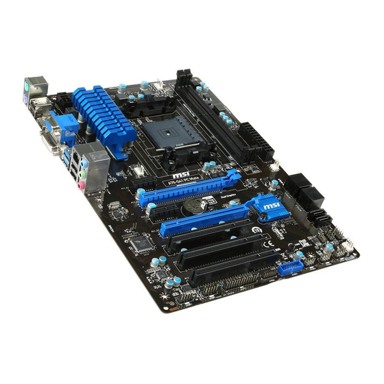
Page 185: Motherboard/ 메인보드/ マザーボード/ 主機板/ 主板
Motherboard/ 메인보드/ マザーボード/ 主機板/ 主板... -
Page 187: Power Connector/ 전원 커넥터/ 電源コネクター/ 電源接頭/ 电源接口
Power Connector/ 전원 커넥터/ 電源コネクター/ 電源接頭/ 电源接口 Youtube http://youtu.be/gkDYyR_83I4 优酷 http://v.youku.com/v_show/ id_XNDkzODU0MDQw.html 또는 または 或是... -
Page 189: Sata Hdd
SATA HDD Youtube 优酷 http://youtu.be/RZsMpqxythc http://v.youku.com/v_show/id_XNDkzODU5MTky.html 또는 または 或是 또는 または 或是... -
Page 190: Msata Ssd
mSATA SSD A-10... -
Page 191: Front Panel Connector/ 전면 패널 커넥터/ フロントパネルコネクター/ 面板接頭/ 前置面板接口
Front Panel Connector/ 전면 패널 커넥터/ フロントパネルコネクター/ 面板接頭/ 前置面板接口 优酷 Youtube JFP1 http://v.youku.com/v_show/ http://youtu.be/DPELIdVNZUI id_XNDkyOTg3NjMy.html JAUD1 A-11... -
Page 192: Peripheral Connector/ 주변 커넥터/ 周辺機器のコネクター/ 週邊接頭/ 周边接口
Peripheral Connector/ 주변 커넥터/ 周辺機器のコネクター/ 週邊接頭/ 周边接口 USB2.0 또는 または 或是 USB3.0 A-12... -
Page 193: Graphics Card/ 그래픽 카드/ グラフィックスカード/ 顯示卡/ 显卡
Graphics Card/ 그래픽 카드/ グラフィックスカード/ 顯示卡/ 显卡 优酷 Youtube http://youtu.be/mG0GZpr9w_A http://v.youku.com/v_show/ id_XNDkyOTc3MzQ4.html A-13... - Page 194 A-14...
- Page 195 产品中有毒有害物质或元素名称及含量 根据中国<电子信息产品污染控制管理办法> 有毒有害物质或元素 多溴 多溴 部件名称 铅 汞 镉 六价铬 联苯 二苯醚 (Pb) (Hg) (Cd) (Cr6+) (PBB) (PBDE) 印刷电路板组件* 电池** 外部信号连接头 线材 O: 表示该有毒有害物质在该部件所有均质材料中的含量均在SJ/T11363-2006标准规定的限量要求下。 X: 表示该有毒有害物质至少在该部件的某一均质材料中的含量超出SJ/T11363-2006标准规定的限量要 求,但所有部件都符合欧盟RoHS要求。 * 印刷电路板组件: 包括印刷电路板及其构成的零部件。 ** 电池本体上如有环保使用期限标识,以本体标识为主。 ■ 上述有毒有害物质或元素清单会依型号之部件差异而有所增减。 ■ 產品部件本体上如有环保使用期限标识,以本体标识为主。...
Need help?
Do you have a question about the A88X-G41 PC Mate and is the answer not in the manual?
Questions and answers