Table of Contents
Advertisement
Available languages
Available languages
Copyright Notice
The material in this document is the intellectual property of MICRO-STAR
INTERNATIONAL. We take every care in the preparation of this document, but no
guarantee is given as to the correctness of its contents. Our products are under
continual improvement and we reserve the right to make changes without notice.
Trademarks
All trademarks in this manual are properties of their respective owners.
MSI
®
is registered trademark of Micro-Star Int'l Co.,Ltd.
®
NVIDIA
is registered trademark of NVIDIA Corporation.
ATI
®
is registered trademark of AMD Corporation.
®
AMD
is registered trademarks of AMD Corporation.
®
Intel
is registered trademarks of Intel Corporation.
Windows
®
is registered trademarks of Microsoft Corporation.
®
AMI
is registered trademark of American Megatrends Inc.
Award
®
is a registered trademark of Phoenix Technologies Ltd.
Sound Blaster
®
Realtek
is registered trademark of Realtek Semiconductor Corporation.
JMicron
®
is registered trademark of JMicron Technology Corporation.
Netware
®
is registered trademark of Novell, Inc.
®
ASMedia
is registered trademark of ASMedia Technology Inc.
iPad, iPhone, and iPod are trademarks of Apple Inc.
Qualcomm Atheros and Killer are trademarks of Qualcomm Atheros Inc.
Revision History
Revision
Revision History
V6.3
Release for V2 series
®
is registered trademark of Creative Technology Ltd.
1
Date
2015/ 01
G52-7721107
Advertisement
Table of Contents

Subscribe to Our Youtube Channel
Related Manuals for MSI V2 Series


Summary of Contents for MSI V2 Series
- Page 1 ASMedia Technology Inc. iPad, iPhone, and iPod are trademarks of Apple Inc. Qualcomm Atheros and Killer are trademarks of Qualcomm Atheros Inc. Revision History Revision Revision History Date V6.3 Release for V2 series 2015/ 01 G52-7721107...
- Page 2 Safety Instructions Always read the safety instructions carefully. Keep this User’s Manual for future reference. Keep this equipment away from humidity. The openings on the enclosure are for air convection hence protects the equipment from overheating. DO NOT COVER THE OPENINGS. Make sure the voltage of the power source is at 110/220V before connecting the equipment to the power inlet.
- Page 3 FCC-B Radio Frequency Interference Statement This equipment has been tested and found to comply with the limits for a Class B digital device, pursuant to Part 15 of the FCC Rules. These limits are designed to provide reasonable protection against harmful interference in a residential installation.
- Page 4 In compliance with chemical substances regulations, such as the EU REACH Regulation (Regulation EC No. 1907/2006 of the European Parliament and the Council), MSI provides the information of chemical substances in products at: http://www.msi.com/html/popup/csr/evmtprtt_pcm.html Japan JIS C 0950 Material Declaration...
- Page 5 Turkey EEE regulation Conforms to the EEE Regulations of the Republic Of Turkey Ukraine restriction of hazardous substances The equipment complies with requirements of the Technical Regulation, approved in terms of restrictions for the use of certain dangerous substances in electrical and electronic equipment.
- Page 6 MSI will comply with the product take back requirements at the end of life of MSI-branded products that are sold into the EU.
- Page 7 MSI zal overeenkomstig de richtlijn handelen voor de producten die de merknaam MSI dragen en verkocht zijn in de EU. Deze goederen kunnen geretourneerd worden op lokale inzamelingspunten.
- Page 8 EU-n belül értékesített termékek esetében, azok élettartamának végén. Az ilyen ITALIANO Per proteggere l’ambiente, MSI, da sempre amica della natura, ti ricorda che…. In base alla Direttiva dell’Unione Europea (EU) sullo Smaltimento dei Materiali Elettrici ed Elettronici, Direttiva 2002/96/EC in vigore dal 13 Agosto 2005, prodotti appartenenti alla categoria dei Materiali Elettrici ed Elettronici non possono più...
-
Page 9: Table Of Contents
Contents English ..................11 ..................12 Back Panel ......................15 ..................16 Memory Installation ....................18 Internal Connectors....................19 BIOS Setup ......................27 ..................33 ......................34 .........................37 ....................38 ......................40 ......................41 .......................49 ..................55 ......................56 Panneau Arrière ......................59 Installation d'APU et son ventilateur ...............60 Installation de mémoire ...................62 Connecteurs internes ....................63 ....................71 Deutsch ..................77 ......................78... - Page 10 .................121 ........................122 ........................125 ....................126 ........................128 ........................129 ......................137 .................143 ......................144 ........................147 ...................148 ......................150 ........................151 ......................159 ..................165 ....................166 ......................169 ................170 ......................172 .....................173 ......................181...
-
Page 11: English
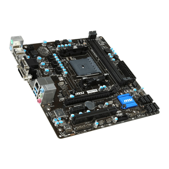
English Thank you for choosing the A88XM-E35 V2/ A88XM-P33 V2/ A78M-E35 V2 Series (MS-7721 v6.X) Micro-ATX motherboards. The A88XM-E35 V2/ A88XM-P33 V2/ A78M-E35 V2 Series motherboards are based on AMD A88X/ A78 chipset for the A88XM-E35 V2/ A88XM-P33 V2/ A78M-E35 V2 Series motherboards deliver a high performance and professional desktop platform solution. - Page 12 Support Chipset AMD A88X/ A78 Memory 2x DDR3 memory slots supporting up to 32GB Support Supports DDR3 2133/ 1866/ 1600/ 1333 MHz Dual channel memory architecture Expansion Slots 1x PCIe 2.0 x1 slot 1x PCI slot Graphics 1x VGA port, supporting a maximum resolution of 1920x1200 @ 60Hz, 24bpp 1x DVI-D port, supporting a maximum resolution of 2560x1600@60Hz, 24bpp/ 1920x1200 @ 60Hz, 24bpp...
- Page 13 AMD A88X/ A78 Chipset - 4x USB 3.0 ports (2 ports on the back panel, 2 ports available through the internal USB connectors) - 8x USB 2.0 ports (4 ports on the back panel, 4 ports available through the internal USB connectors) Audio Realtek ®...
- Page 14 ACPI 5.0, PnP 1.0a, SM BIOS 2.7, DMI 2.0 Multi-language Form Factor Micro-ATX Form Factor 8.9 in. x 8.5 in. (22.6 cm x 21.6 cm) For the latest information about CPU, please visit http://www.msi.com/cpu-support/ For more information on compatible components, please visit http://www.msi.com/test-report/...
-
Page 15: Back Panel
Back Panel A88XM-E35 V2/ A78M-E35 V2 PS/2 Mouse Line-In USB 2.0 Line-Out DVI-D HDMI PS/2 Keyboard USB 3.0 A88XM-P33 V2 PS/2 Mouse Line-In USB 2.0 DVI-D Line-Out PS/2 Keyboard USB 3.0... - Page 16 When installing a APU, always remember to install a APU heatsink. An APU heatsink is necessary to prevent overheating and maintain system stability. Follow the steps below to ensure correct APU and heatsink installation. Wrong installation can damage both the APU and the motherboard. Pull the lever sideways away from the socket.
- Page 17 Locate the CPU fan connector on the motherboard. Position the cooling set onto the retention mechanism. Hook one end of the clip Then press down the other end of the clip to fasten the cooling set on the top of the retention mechanism.
-
Page 18: Memory Installation
Memory Installation Video Demonstration Watch the video to learn how to install memories at the address below. http://youtu.be/76yLtJaKlCQ Important DDR3 memory modules are not interchangeable with DDR2, and the DDR3 standard is not backward compatible. Always install DDR3 memory modules in DDR3 DIMM slots. -
Page 19: Internal Connectors
Internal Connectors JPWR1~2: ATX Power Connectors These connectors allow you to connect an ATX power supply. To connect the ATX cable into the connector. If done correctly, the clip on the power cable should be hooked on the motherboard’s power connector. Video Demonstration Watch the video to learn how to install power supply connectors. - Page 20 SATA1~6: SATA Connectors (optional) This connector is a high-speed SATA interface port. Each connector can connect to one SATA device. SATA devices include disk drives (HDD), solid state drives (SSD), and optical drives (CD/ DVD/ Blu-Ray). Video Demonstration Watch the video to learn how to Install SATA HDD. http://youtu.be/RZsMpqxythc SATA4 SATA5...
- Page 21 JCI1: Chassis Intrusion Connector This connector connects to the chassis intrusion switch cable. If the computer case is opened, the chassis intrusion mechanism will be activated. The system will record must enter the BIOS setup and clear the record. CPUFAN,SYSFAN1~2: Fan Power Connectors The fan power connectors support system cooling fans with +12V.
- Page 22 JAUD1: Front Panel Audio Connector This connector allows you to connect the front audio panel located on your computer case. JFP1, JFP2: System Panel Connectors These connectors connect to the front panel switches and LEDs. When installing the front panel connectors, please use the optional M-Connector to simplify installation. Plug all the wires from the computer case into the M-Connector and then plug the M-Connector into the motherboard.
- Page 23 JUSB1~2: USB 2.0 Expansion Connectors This connector is designed for connecting high-speed USB peripherals such as USB HDDs, digital cameras, MP3 players, printers, modems, and many others. Important Note that the VCC and GND pins must be connected correctly to avoid possible damage.
- Page 24 JTPM1: TPM Module Connector This connector connects to a TPM (Trusted Platform Module). Please refer to the TPM security platform manual for more details and usages. JLPT1: Parallel Port Header (optional) This connector is used to connect an optional parallel port bracket. The parallel port is a standard printer port that supports Enhanced Parallel Port (EPP) and Extended Capabilities Parallel Port (ECP) mode.
- Page 25 JBAT1: Clear CMOS Jumper There is CMOS RAM onboard that is external powered from a battery located on the can automatically boot into the operating system (OS) every time it is turned on. If Keep Data Clear Data Important Afterwards, open the jumper . Do not clear the CMOS RAM while the system is on because it will damage the motherboard.
- Page 26 PCI_E1~2: PCIe Expansion Slots The PCIe slot supports the PCIe interface expansion card. PCIe x16 Slot PCIe x1 Slot PCI1: PCI Expansion Slot The PCI slot supports the PCI interface expansion card.. PCI Slot Important unplug the power supply power cable from the power outlet. Read the expansion card’s documentation to check for any necessary additional hardware or software changes.
-
Page 27: Bios Setup
(optional) on the motherboard to enable the system going to BIOS setup directly at next boot. Click "GO2BIOS" tab on "MSI Fast Boot" utility screen. Important Please be sure to install the “MSI Fast Boot” utility before using it to enter the BIOS setup. - Page 28 Overview After entering BIOS, the following screen is displayed. Temperature monitor Language System information Virtual OC Genie Button Boot device priority bar BIOS menu selection BIOS menu selection Menu display OC Menu Important Overclocking your PC manually is only recommended for advanced users. Overclocking is not guaranteed, and if done improperly, can void your warranty or severely damage your hardware.
- Page 29 Current CPU/ DRAM Frequency These items show the current frequencies of installed CPU and Memory. Read-only. CPU Base Frequency (MHz) [Default] Sets the CPU Base clock. You may overclock the CPU by adjusting this value. Please note that overclocking behavior and stability is not guaranteed. This item appears when the installed processor supports this function.
- Page 30 DRAM Frequency [Auto] Sets the DRAM frequency. Please note the overclocking behavior is not guaranteed. Adjusted DRAM Frequency Shows the adjusted DRAM frequency. Read-only. XMP is the overclocking technology by memory module. This item will be available when you install the memory modules that support XMP technology. When the XMP is Enabled, the AMP will be forced to be disabled.
- Page 31 DRAM Voltage [Auto] Sets DRAM voltage. If set to "Auto", BIOS will set DRAM voltage automatically or you can set it manually. Spread Spectrum This function reduces the EMI (Electromagnetic Interference) generated by modulating clock generator pulses. [Enabled] Enables the spread spectrum function to reduce the EMI (Electromagnetic Interference) problem.
- Page 32 CPU Features AMD Cool’n’Quiet [Auto] Enabled or disabled AMD Cool’n’Quiet function. [Auto] Depends on AMD Design. [Enable] Enables AMD Cool’n’Quiet function. The Cool’n’Quiet and power consumption. [Disabled] Disables this function. Important When adjust CPU Ratio then Cool’n’Quiet function will be disabled automatically. For CPU which supports the Turbo Core Tech., please set AMD Turbo Core Technology and AMD Cool’n’Quiet as Disabled to retain the default CPU core speed.
- Page 33 CPUFAN Top : mouse port Bottom: keyboard port JPWR2 USB2.0 ports USB2.0 ports Top: VGA Port Bottom: DV Port JUSB_PW2 HDMI port Top: LAN Jack JTPM1 Bottom: USB3.0 ports JCOM1 SYSFAN2 T:Line-In M:Line- Out B:MIC-Int PCI_E1 PCI_E2 JCI1 JBAT1 PCI1 JUSB_PW1 JUSB3 JFP2...
- Page 34 AMD A88X/ A78 A88XM-E35 V2/ A78M-E35 V2 - AMD A88X/ A78 - SATA 6Gb/s A88XM-P33 V2 - AMD A88X - SATA 6Gb/s...
- Page 35 - USB 3.0 - USB 2.0 Realtek ® Realtek ®...
- Page 36 UEFI AMI BIOS ACPI 5.0, PnP 1.0a, SM BIOS 2.7, DMI 2.0 8.9 in. x 8.5 in. (22.6 cm x 21.6 cm)
- Page 37 A88XM-E35 V2/ A78M-E35 V2 USB 2.0 DVI-D HDMI USB 3.0 A88XM-P33 V2 USB 2.0 DVI-D USB 3.0...
- Page 40 http://youtu.be/76yLtJaKlCQ...
- Page 41 http://youtu.be/gkDYyR_83I4 JPWR2 JPWR1...
- Page 42 http://youtu.be/RZsMpqxythc SATA4 SATA5 SATA6 SATA1 SATA2 SATA3...
- Page 43 CPUFAN/ SYSFAN1 SYSFAN2...
- Page 44 http://youtu.be/DPELIdVNZUI JFP1 JFP2...
- Page 47 JUSB_PW1 JUSB_PW2...
- Page 49 Press DEL key to enter Setup Menu, F11 to enter Boot Menu...
- Page 50 Virtual OC...
- Page 51 Current CPU/ DRAM Frequency CPU Base Frequency (MHz) [Default] Adjust CPU Ratio [Auto] Adjusted CPU Frequency Adjust CPU-NB Ratio [Auto] Adjusted CPU-NB Frequency CPU Core Control [Auto] AMD Turbo Core Technology [Auto] Adjust Turbo Core Ratio [Auto] Adjusted Turbo Core Frequency Adjust GPU Engine Frequency [Auto] Adjusted GPU Engine Frequency DRAM Frequency [Auto]...
- Page 52 Adjusted DRAM Frequency DRAM Timing Mode [Auto] DRAM Voltage [Auto] Spread Spectrum...
- Page 53 CPU Memory Changed Detect [Enabled] OC Retry Count CPU Features AMD Cool’n’Quiet [Auto] SVM Mode [Enabled]...
- Page 54 Core C6 State [Enabled]...
- Page 55 Merci d’avoir choisi une carte mère Micro-ATX de la série A88XM-E35 V2/ A88XM-P33 V2/ A78M-E35 V2 (MS-7721 v6.X). La série A88XM-E35 V2/ A88XM-P33 V2/ A78M-E35 V2 est basée sur le chipset AMD A88X/ A78 pour une avancés, les cartes mères de la série A88XM-E35 V2/ A88XM-P33 V2/ A78M-E35 professionnels qu’aux particuliers.
- Page 56 Processeur Chipset AMD A88X/ A78 Mémoire supportée Support DDR3 2133/ 1866/ 1600/ 1333 MHz Architecture mémoire double canal Emplacement d’extension 1x emplacement PCIe 2.0 x1 1x emplacement PCI Graphiques 1x port VGA, support une résolution au maximumde 1920x1200 @ 60Hz, 24bpp 1x port DVI-D, support une résolution au maximum de 2560x1600@60Hz, 24bpp/ 1920x1200 @ 60Hz, 24bpp 1x port HDMI (en option), support une résolution au maximum...
- Page 57 Chipset AMD A88X/ A78 - 4x ports USB 3.0 (2 ports sur le panneau arrière, 2 ports disponibles via le connecteur USB intégré) - 8x ports USB 2.0 (4 ports sur le panneau arrière, 4 ports disponibles via le connecteur USB intégré) Audio Realtek ®...
- Page 58 ACPI 5.0, PnP 1.0a, SM BIOS 2.7, DMI 2.0 Multi-langue Dimension Dimension Micro-ATX 8.9 in. x 8.5 in. (22.6 cm x 21.6 cm) Pour plus d’information sur le CPU, veuillez visiter http://www.msi.com/cpu-support/ Pour plus d’information sur les composants compatibles, veuillez visiter http://www.msi.com/test-report/...
-
Page 59: Panneau Arrière
Panneau Arrière A88XM-E35 V2/ A78M-E35 V2 Souris PS/2 Ligne-In USB 2.0 Ligne-Out DVI-D HDMI Clavier PS/2 USB 3.0 A88XM-P33 V2 Souris PS/2 Ligne-In USB 2.0 Ligne-Out DVI-D Clavier PS/2 USB 3.0... -
Page 60: Installation D'apu Et Son Ventilateur
Installation d'APU et son ventilateur Quand vous installez l'APU, assurez-vous que l'APU est doté d'un système de Suivez les étapes suivantes pour installer l'APU et son ventilateur correctement. Une mauvaise installation peut endommager votre APU et la carte mère. photot. L'APU ne s’y installe que dans le position correcte. Si l'APU est correctement installé, les pins sont complètement intégrés dans la douille et ils sont invisibles. - Page 61 Localisez le connecteur de ventilateur CPU sur la carte mère. Posez le ventilateur sur le mécanisme de rétention. Crochez un côté du clip d’abord. Fixez le levier. Attachez le câble du ventilateur de l'APU au connecteur du ventilateur de l'APU Important oeil sur vos doigts, parce qu’une fois que le crochet de sécurité...
-
Page 62: Installation De Mémoire
Installation de mémoire Démonstration de vidéo Voir le vidéo sur l'installation des mémoires sur le site ci-dessous. http://youtu.be/76yLtJaKlCQ Important Les modules de mémoire DDR3 ne sont pas interchangeables avec les modules DDR2. Vous devez toujours installer les modules de mémoire DDR3 dans les emplacements DDR3 DIMM. -
Page 63: Connecteurs Internes
Connecteurs internes JPWR1~2 : Connecteur d'alimentation ATX Ce connecteur vous permet de relier une alimentation ATX. Pour cela, alignez le câble d’alimentation avec le connecteur et appuyez fermement le câble dans le connecteur. Si ceci est bien fait, la pince sur le câble d’alimentation doit être accrochée sur le connecteur d’alimentation de la carte mère. - Page 64 SATA1~6 : Connecteurs SATA (en option) Ce connecteur est un port d’interface SATA haut débit. Chaque connecteur peut être état solide (SSD), et lecteurs optiques (CD/ DVD/ Blu-Ray). Démonstration de vidéo Voir le vidéo sur l’installation d’un SATA HDD. http://youtu.be/RZsMpqxythc SATA4 SATA5 SATA6...
- Page 65 JCI1 : Connecteur Intrusion Châssis désactiver l’alerte. CPUFAN,SYSFAN1~2 : Connecteur d’alimentation du ventilateur Les connecteurs d’alimentation du ventilateur supportent les ventilateurs de type +12V. Si la carte mère est équipée d’un moniteur du matériel système intégré, vous le ventilateur de l’unité centrale. N’oubliez pas de connecter tous les ventilateurs. quel connecteur de ventilateur système.
- Page 66 JAUD1 : Connecteur audio panneau avant Ce connecteur vous permet de connecter le panneau audio avant. Il est conforme au guide de conception de la connectivité Entrée/sortie du panneau avant. JFP1, JFP2 : Connecteur panneau système Ces connecteurs se connectent aux interrupteurs et LEDs du panneau avant. Lors de l’installation des connecteurs du panneau avant, veuillez utiliser le M-Connector Démonstration de vidéo Voir le vidéo pour l’installation des connecteurs du panneau avant.
- Page 67 JUSB1~2 : Connecteurs d’extension USB 2.0 que les disques durs USB, les appareils photo numériques, les lecteurs MP3, les imprimantes, les modems et les appareils similaires. Important tout dommage possible. JUSB3 : Connecteurs d’extension USB 3.0 Le port USB 3.0 est rétro-compatible avec les périphériques USB 2.0. Il supporte un Important d’éviter tout dommage possible.
- Page 68 JTPM1 : Connecteur de Module TPM Ce connecteur permet de relier un module TPM (Trusted Platform Module) en option. Veuillez vous référer au manuel du module TPM pour plus de détails. JLPT1 : Connecteur de port parallèle (en option) parallèle est un port d’imprimante standard qui supporte les modes Enhanced Parallel Port (EPP) et Extended Capabilities Parallel Port (ECP).
- Page 69 Il y a un CMOS RAM intégré, qui est alimenté par une batterie externe située sur le CMOS RAM, le système peut lancer automatiquement le système d’exploitation Conserver les données Important est allumé; cela endommagerait la carte mère. JUSB_PW1, JUSB_PW2 : Cavaliers d’alimentation USB Ces cavaliers sont utilisés pour assigner lequel des périphérique USB et PS/2 supporte le mode «...
- Page 70 PCI_E1~2 : Emplacements d’extension PCIe L’emplacement PCIe supporte l'interface de carte d'extension PCIe. Emplacement PCIe x16 Emplacement PCIe x1 PCI1 : Emplacements d’extension PCI L’emplacement PCI supporte l’interface de carte d’extension PCI. Emplacement PCI Important Lorsque vous ajoutez ou retirez une carte d’extension, assurez-vous que le PC n’est du matériel ou logiciel ajoutés.
- Page 71 RESET (Réinitialiser). Vous pouvez également redémarrer le ou appuyez sur le bouton “GO2BIOS" physique (en option) sur la carte mère pour démarrage. Cliquez sur l'onglet "GO2BIOS" depuis l'écran d'utilitaire "MSI Fast Boot". Important Veuillez vous assurer d’avoir installé l’utilitaire “MSI Fast Boot” avant d’utiliser le...
- Page 72 Vue d'ensemble Entrer BIOS, l’écran suivant apparaît. Indicateur température Langue Information du système Bouton virtuel OC Genie Barre priorité de périphérique démarrage Sélection du menu BIOS Sélection du menu BIOS Ecran de menu OC Menu Important L’Overclocking manuel du PC n’est recommandé que pour les utilisateurs avancés.
- Page 73 Current CPU/ DRAM Frequency lecture seule. CPU Base Frequency (MHz) [Default] Veuillez noter que le comportement d’overclocking n’est pas garanti. Ce menu apparaît quand le processeur installé prend cette fonction en charge. Adjust CPU Ratio [Auto] Adjusted CPU Frequency Il montre la fréquence ajustée du CPU. En lecture seule. Adjust CPU-NB Ratio [Auto] Adjusted CPU-NB Frequency Il montre la fréquence ajusté...
- Page 74 Adjusted DRAM Frequency Montre la fréquence ajustée DRAM. En lecture seule. XMP est la technologie d’overclocking par le module de mémoire. Ce menu est disponible quand vous installez les modules de mémoire prenant la technologie XMP en charge. Lorsque le XMP est activé, AMP est désactivé forcément. [Disabled] Désactive cette fonction.
- Page 75 Spread Spectrum Cette fonction réduit les interférences électromagnétiques EMI (Electromagnetic Interference) en réglant les impulsions du générateur d'horloge. [Enabled] Active la fonction spread spectrum pour réduire le problème EMI (Electromagnetic Interference) . [Disabled] Améliore la capabilité d’overclocking de le base clock CPU. Important Si vous n’avez pas de problème d’EMI, laissez l’option sur [Disable], ceci vous permet d’avoir une stabilité...
- Page 76 SVM Mode [Enabled] Active ou désactive la virtualisation du CPU. forme de fonctioner aux multiples systèmes d'exploitation en partitions indépendentes. Le système peut fonctionner comme de multiple systèmes virtuellement. [Disabled] Désactive cette fonction. Core C6 State [Enabled] Active ou désactive le support d'état C6. [Enabled] Lorsque le CPU entre en état C6, tous les coeurs conservent Il prend plus de temps pour réveiller le CPU de l'état C6.
-
Page 77: Deutsch
Deutsch Danke, dass Sie das A88XM-E35 V2/ A88XM-P33 V2/ A78M-E35 V2 (MS- 7721 v6.X) Micro-ATX Motherboard gewählt haben. Diese A88XM-E35 V2/ A88XM-P33 V2/ A78M-E35 V2 Motherboard basiert auf dem AMD A88X/ A78 um den hochentwickelten AMD FM2+/ FM2 Prozessor zu unterstützen, stellt die A88XM-E35 V2/ A88XM-P33 V2/ A78M-E35 V2 die ideale Lösung zum Aufbau eines professionellen Hochleistungsdesktopsystems dar. - Page 78 Prozessor Chipsatz AMD A88X/ A78 Speicher 2x DDR3 Speicherplätze unterstützen bis zu 32GB Unterstützt DDR3 2133/ 1866/ 1600/ 1333 MHz Dual-Kanal-Speicherarchitektur Erweiterung- anschlüsse 1x PCIe 2.0 x1-Steckplatz 1x PCI-Steckplatz Onboard- 1920x1200 @ 60Hz, 24bpp von 2560x1600@60Hz, 24bpp/ 1920x1200 @ 60Hz, 24bpp 1x HDMI -Anschluss (optional), unterstützt eine 1920x1200@60Hz, 36bpp Aufbewahrung...
- Page 79 AMD A88X/ A78 Chipsatz - 4x USB 3.0 Anschlüsse (2 Anschlüsse an der Rückwand, 2 Anschlüsse stehen durch die internen USB Anschlüsse zur Verfügung) - 8x USB 2.0 Anschlüsse (4 Anschlüsse an der Rückwand, 4 Anschlüsse stehen durch die internen USB Anschlüsse zur Verfügung) Audio Realtek...
- Page 80 BIOS 64 Mb Flash Funktionen UEFI AMI BIOS ACPI 5.0, PnP 1.0a, SM BIOS 2.7, DMI 2.0 Mehrsprachenunterstützung Form Faktor Micro-ATX Form Faktor 8,9 Zoll x 8,5 Zoll (22,6 cm x 21,6 cm) http://www.msi.com/cpu-support/ Sie unter http://www.msi.com/test-report/...
-
Page 81: Rücktafel-Übersicht
Rücktafel-Übersicht A88XM-E35 V2/ A78M-E35 V2 PS/2 Maus Line-In USB 2.0 Line-Out DVI-D HDMI PS/2 Tastatur USB 3.0 A88XM-P33 V2 PS/2 Maus Line-In USB 2.0 Line-Out DVI-D PS/2 Tastatur USB 3.0... - Page 82 Wenn Sie die APU einbauen, denken sie bitte daran einen APU-Kühler zu installieren. Ein APU-Kühlkörper ist notwendig, um eine Überhitzung zu vermeiden und die Systemstabilität beizubehalten. Befolgen Sie die nachstehenden Schritte, um die richtige APU und APU-Kühlkörper Installation zu gewährleisten. Ein fehlerhafter Einbau führt zu Schäden an der APU und dem Motherboard.
- Page 83 Setzen Sie den Kühler auf die Kühlerhalterung und hacken Sie zuerst ein Ende des Kühlers an dem Modul fest. Dann drücken Sie das andere Ende des Bügels herunter, um den Kühler auf der der Seite fest. Drücken Sie den Sicherungshebel. Verbinden Sie das Stromkabel des APU Lüfters mit dem Anschluss auf dem Motherboard.
-
Page 84: Speicher
Speicher Video-Demonstration Anhand dieses Video an untenstehende Adresse lernen Sie, wie Sie die Speichermodule installieren. http://youtu.be/76yLtJaKlCQ Wtichtig DDR3 und DDR2 können nicht untereinander getauscht werden und der Standard DDR3 ist nicht abwärtskompatibel. Installieren Sie DDR3 Speichermodule stets in DDR3 DIMM Slots. Verwenden Sie die Speichermodule des gleichen Typs und identischer Speicherdichte im Zweikanalbetrieb, um die Systemstabilität zu gewährleisten. -
Page 85: Interne Anschlüsse
Interne Anschlüsse JPWR1~2: ATX Stromanschlüsse Mit diesem Anschluss verbinden Sie den ATX Stromanschlusse. Achten Sie bei dem Verbinden des ATX Stromanschlusses darauf, dass der Anschluss des Netzteils richtig auf den Anschluss an der Hauptplatine ausgerichtet ist. Drücken Sie dann den Anschluss des Netzteils fest nach unten, um eine richtige Verbindung zu gewährleisten. - Page 86 SATA1~6: SATA Anschlüsse (optional) Dieser Anschluss basiert auf der Hochgeschwindigkeitsschnittstelle Serial ATA (SATA). Pro Anschluss kann ein Serial ATA Gerät angeschlossen werden. Zu Serial ATA Geräten gehören Festplatten (HDD), SSD Festplatten (SSD) und optische Laufwerke (CD-/DVD-/Blu-Ray-Laufwerke). Video-Demonstration Anhand dieses Video an untenstehende Adresse lernen Sie, wie Sie eine SATA-Featplatte installieren.
- Page 87 JCI1: Gehäusekontaktanschluss Dieser Anschluss wird mit einem Kontaktschalter verbunden. Wenn das PC-Gehäuse wird auf dem Bildschirm angezeigt. Um die Warnmeldung zu löschen, muss das BIOS aufgerufen und die Aufzeichnung gelöscht werden. CPUFAN,SYSFAN1~2: Stromanschlüsse für Lüfter Die Anschlüsse unterstützen aktive Systemlüfter mit +12V. Ist Ihr Motherboard mit einem Chipsatz zur Überwachung der Systemhardware versehen, dann brauchen Sie einen speziellen Lüfter mit Geschwindigkeitsregelung, um die Vorteile der Steuerung des CPU Lüfters zu nutzen.
- Page 88 JAUD1: Audioanschluss des Frontpanels Dieser Anschluss ermöglicht den Anschluss von Audio Ein- und Ausgängen eines Frontpanels. JFP1, JFP2: Systemtafelanschlüsse Diese Anschlüsse sind für das Frontpanel angelegt. Sie dienen zum Anschluss der Schalter und LEDs des Frontpanels. JFP1 erfüllt die Anforderungen des “Intel® Front Panel I/O Connectivity Design Guide”.
- Page 89 JUSB1~2: USB 2.0 Erweiterungsanschlüsse Dieser Anschluss eignet sich für die Verbindung der Hochgeschwindigkeits- USB- Peripheriegeräte, wie z.B. USB Festplattenlaufwerke, Digitalkameras, MP3-Player, Drucker, Modems und ähnliches. Wichtig Bitte beachten Sie, dass Sie die mit VCC (Stromführende Leitung) und GND (Erdlei- tung) bezeichneten Pins korrekt verbinden müssen, ansonsten kann es zu Schäden kommen.
- Page 90 JTPM1: TPM Module Anschluss Dieser Anschluss wird für das TPM Modul (Trusted Platform Module) verwendet. Weitere Informationen über den Einsatz des optionalen TPM Modules entnehmen Sie bitte dem TPM Plattform Handbuch. JLPT1: Parallele Schnittstelle (optional) Die Parallele Schnittstelle ist eine Standard Druckerschnittstelle, die ebenso als Enhanced Parallel Port (EPP) und als Extended Capabilities Parallel Port (ECP) betrieben werden kann.
- Page 91 JBAT1: Steckbrücke zur CMOS-Löschung Der Onboard CMOS Speicher (RAM) wird durch eine externe Spannungsversorgung durch eine Batterie auf dem Motherboard versorgt, um die Daten der wollen, müssen Sie die Steckbrücke für kurze Zeit umsetzen. Halten Sie sich an die Daten beibehalten CMOS-Daten löschen Wichtig Wenn das System ausgeschaltet ist, können Sie die Steckbrücke stecken, um die...
- Page 92 PCI_E1~2: PCIe Erweiterungssteckplätze Der PCIe Steckplatz unterstützt PCIe-Erweiterungskarten. PCIe x16-Steckplatz PCIe x1-Steckplatz PCI1: PCI Erweiterungssteckplatz Der PCIe Steckplatz unterstützt PCIe-Erweiterungskarten. PCI-Steckplatz Wichtig Achten Sie darauf, dass Sie den Strom abschalten und das Netzkabel aus der Steckdose herausziehen, bevor Sie eine Erweiterungskarte installieren oder entfernen.
-
Page 93: Bios Setup
ANSCHALTEN, oder die “RESET”-Taste am Gehäuse betätigen. Sie können das MSI bietet zusätzlich zwei Methoden, um das BIOS-Setup zu gelangen. Klicken Sie auf das Auswahlfeld “GO2BIOS” des Bildschirms "MSI Fast Boot" oder drücken Sie die Taste “GO2BIOS" (optional) auf dem Motherboard, um beim nächsten Systemstart automatisch ins BIOS Menu zu wechseln. - Page 94 Überbilck Nach dem Aufrufen des BIOS, sehen Sie die folgende Anzeige. Temperatur-überwachung Sprache System- Information Virtual OC Genie Taste Bootgeräte- Prioritäts- leiste BIOS-Menü- Auswahl BIOS-Menü- Auswahl Menüanzeige OC-Menü Wichtig Die Übertaktung ist nur für fortgeschrittene Benutzer zu empfehlen. Die erfolgreiche Übertaktung ist nicht gewährleistet. Die Anwendung von Übertaktungsmaßnahmen kann zu Verlust der Garantie oder zur Beschädigung der Hardware führen.
- Page 95 Current CPU/ DRAM Frequency Zeigt die derzeitigen Frequenz der installierten CPU und Speicher. Dies ist nur eine CPU Base Frequency (MHz) [Default] Hier können Sie den CPU Grundtakt anpassen. Sie können die CPU übertakten, indem Sie diesen Wert verändern. Bitte beachten Sie, dass die Übertaktung (und das Ergebnis) und die Stabilität nicht gewährleistet sind.
- Page 96 DRAM Frequency [Auto] Setzen Sie die DRAM Frequenz. Bitte beachten Sie, dass ein zuverlässiges Übertaktungsverhalten nicht garantiert werden kann. Adjusted DRAM Frequency Speichermodule aus dem PC-Bereich und können Sie kompatiblen DDR3-Speicher übertakten. Diese Option steht zur Verfügung, wenn die installierten Speichermodule [Disabled] Deaktiviert diese Funktion.
- Page 97 DRAM Voltage [Auto] Setzen die Speicherspannung. Wenn die Einstellung auf [Auto] gesetzt ist, wird das BIOS die Speicher-Spannung automatisch einstellen. Sie können die Einstellungen auch manuell vornehmen. Spread Spectrum Diese Funktion reduziert die EMI (Electromagnetic Interference) durch Modulation Taktgenerator erzeugten Impulse. [Enabled] Aktiviert die Spread-Spectrum-Funktion, um die elektromagnetische Wechselwirkung zu verringern.
- Page 98 Wichtig Wenn die CPU-Ratio Setting setzt, dann Cool’n’Quiet-Funktion automatisch deaktiviert ist. Für CPU, die die Turbo Core Technologie unterstützt, deaktivieren Sie bitte AMD Turbo Core Technology und AMD Cool’n’Quiet, um die Standard-CPU- Kern Geschwindigkeit beizubehalten. SVM Mode [Enabled] Aktiviert oder deaktiviert die CPU-Virtualisierung. [Enabled] Aktiviert die CPU-Virtualisierung und erlaubt so, mehrere Betriebssysteme in unabhängigen Partitionen ausführen.
- Page 99 CPUFAN Top : mouse port Bottom: keyboard port JPWR2 USB2.0 ports USB2.0 ports Top: VGA Port Bottom: DV Port JUSB_PW2 HDMI port Top: LAN Jack JTPM1 Bottom: USB3.0 ports JCOM1 SYSFAN2 T:Line-In M:Line- Out B:MIC-Int PCI_E1 PCI_E2 JCI1 JBAT1 PCI1 JUSB_PW1 JUSB3 JFP2...
- Page 100 AMD A88X/ A78 36bpp A88XM-E35 V2/ A78M-E35 V2 AMD A88X/ A78 (A88XM-E35 V2) A88XM-P33 V2 AMD A88X...
- Page 101 Realtek ® ALC887 Codec Realtek ® 1x 24- 1x 4- USB 2.0) USB 3.0) (A88XM-E35 V2/ A78M-E35 V2)
- Page 102 BIOS UEFI AMI BIOS ACPI 5.0, PnP 1.0a, SM BIOS 2.7, DMI 2.0...
- Page 103 A88XM-E35 V2/ A78M-E35 V2 USB 2.0 DVI-D HDMI USB 3.0 A88XM-P33 V2 USB 2.0 DVI-D USB 3.0...
- Page 106 http://youtu.be/76yLtJaKlCQ...
- Page 107 http://youtu.be/gkDYyR_83I4 JPWR2 JPWR1...
- Page 108 http://youtu.be/RZsMpqxythc SATA4 SATA5 SATA6 SATA1 SATA2 SATA3...
- Page 109 CPUFAN/ SYSFAN1 SYSFAN2...
- Page 110 http://youtu.be/DPELIdVNZUI JFP1 JFP2...
- Page 113 JUSB_PW1 JUSB_PW2...
- Page 116 BIOS OC Genien...
- Page 117 Current CPU/ DRAM Frequency CPU Base Frequency (MHz) [Default] Adjust CPU Ratio [Auto] Adjusted CPU Frequency Adjust CPU-NB Ratio [Auto] Adjusted CPU-NB Frequency CPU Core Control [Auto] AMD Turbo Core Technology [Auto] Cool’n’Quiet Technology. Adjust Turbo Core Ratio [Auto] Adjusted Turbo Core Frequency Adjust GPU Engine Frequency [Auto]...
- Page 118 Adjusted GPU Engine Frequency DRAM Frequency [Auto] Adjusted DRAM Frequency DRAM Timing Mode [Auto]...
- Page 119 DRAM Voltage [Auto] Spread Spectrum CPU Memory Changed Detect [Enabled] BIOS. OC Retry Count CPU Features...
- Page 120 AMD Cool’n’Quiet [Auto] SVM Mode [Enabled] Core C6 State [Enabled]...
- Page 121 CPUFAN Top : mouse port Bottom: keyboard port JPWR2 USB2.0 ports USB2.0 ports Top: VGA Port Bottom: DV Port JUSB_PW2 HDMI port Top: LAN Jack JTPM1 Bottom: USB3.0 ports JCOM1 SYSFAN2 T:Line-In M:Line- Out B:MIC-Int PCI_E1 PCI_E2 JCI1 JBAT1 PCI1 JUSB_PW1 JUSB3 JFP2...
- Page 122 AMD A88X/ A78 1920x1200 @ 60Hz, 24bpp 36bpp and 1920x1200@60Hz, 36bpp A88XM-E35 V2/ A78M-E35 V2 RAID 10 (A88XM-E35 V2) A88XM-P33 V2...
- Page 123 Realtek ® ALC887 Codec Realtek ®...
- Page 124 UEFI AMI BIOS ACPI 5.0, PnP 1.0a, SM BIOS 2.7, DMI 2.0 http://www.msi.com/cpu-support/ http://www.msi.com/test-report/...
- Page 125 A88XM-E35 V2/ A78M-E35 V2 Line-In USB 2.0 Line-Out DVI-D HDMI USB 3.0 A88XM-P33 V2 Line-In USB 2.0 DVI-D Line-Out USB 3.0...
- Page 128 http://v.youku.com/v_show/id_XNDkyOTc5OTMy.html...
- Page 129 http://v.youku.com/v_show/id_XNDkzODU0MDQw.html JPWR2 JPWR1...
- Page 130 http://v.youku.com/v_show/id_XNDkzODU5MTky.html SATA4 SATA5 SATA6 SATA1 SATA2 SATA3...
- Page 131 CPUFAN/ SYSFAN1 SYSFAN2...
- Page 132 ® http://v.youku.com/v_show/id_XNDkyOTg3NjMy.html JFP1 JFP2...
- Page 135 JUSB_PW1 JUSB_PW2...
- Page 137 Press DEL key to enter Setup Menu, F11 to enter Boot Menu...
- Page 138 BIOS menu selection...
- Page 139 Current CPU/ DRAM Frequency CPU Base Frequency (MHz) [Default] Adjust CPU Ratio [Auto] Adjusted CPU Frequency Adjust CPU-NB Ratio [Auto] Adjusted CPU-NB Frequency CPU Core Control [Auto] AMD Turbo Core Technology [Auto] Adjust Turbo Core Ratio [Auto] Adjusted Turbo Core Frequency Adjust GPU Engine Frequency [Auto] Adjusted GPU Engine Frequency...
- Page 140 DRAM Frequency [Auto] Adjusted DRAM Frequency DRAM Timing Mode [Auto] DRAM Voltage [Auto]...
- Page 141 Spread Spectrum CPU Memory Changed Detect [Enabled] OC Retry Count CPU Features AMD Cool’n’Quiet [Auto]...
- Page 142 SVM Mode [Enabled] Core C6 State [Enabled]...
- Page 143 CPUFAN Top : mouse port Bottom: keyboard port JPWR2 USB2.0 ports USB2.0 ports Top: VGA Port Bottom: DV Port JUSB_PW2 HDMI port Top: LAN Jack JTPM1 Bottom: USB3.0 ports JCOM1 SYSFAN2 T:Line-In M:Line- Out B:MIC-Int PCI_E1 PCI_E2 JCI1 JBAT1 PCI1 JUSB_PW1 JUSB3 JFP2...
- Page 144 AMD A88X/ A78 24bpp 24bpp/ 1920x1200 @ 60Hz, 24bpp 1920x1200@120Hz, 36bpp, 1920x1200@60Hz, 36bpp A88XM-E35 V2/ A78M-E35 V2 A88XM-P33 V2...
- Page 145 Realtek ® ALC887 Codec Realtek ®...
- Page 146 UEFI AMI BIOS ACPI 5.0, PnP 1.0a, SM BIOS 2.7, DMI 2.0 Micro-ATX http://www.msi.com/cpu-support/ http://www.msi.com/test-report/...
- Page 147 A88XM-E35 V2/ A78M-E35 V2 HDMI USB 3.0 A88XM-P33 V2 USB 3.0...
- Page 150 http://youtu.be/76yLtJaKlCQ...
- Page 151 http://youtu.be/gkDYyR_83I4 JPWR2 JPWR1...
- Page 152 http://youtu.be/RZsMpqxythc SATA4 SATA5 SATA6 SATA1 SATA2 SATA3 ® ®...
- Page 153 CPUFAN/ SYSFAN1 SYSFAN2...
- Page 154 ® ® http://youtu.be/DPELIdVNZUI JFP1 JFP2...
- Page 157 JUSB_PW1 JUSB_PW2...
- Page 159 Press DEL key to enter Setup Menu, F11 to enter Boot Menu...
- Page 161 Current CPU/ DRAM Frequency CPU Base Frequency (MHz) [Default] Adjust CPU Ratio [Auto] Adjusted CPU Frequency Adjust CPU-NB Ratio [Auto] Adjusted CPU-NB Frequency CPU Core Control [Auto] AMD Turbo Core Technology [Auto] Adjust Turbo Core Ratio [Auto] Adjusted Turbo Core Frequency Adjust GPU Engine Frequency [Auto] Adjusted GPU Engine Frequency...
- Page 162 DRAM Frequency [Auto] Adjusted DRAM Frequency DRAM Timing Mode [Auto] DRAM Voltage [Auto]...
- Page 163 Spread Spectrum CPU Memory Changed Detect [Enabled] OC Retry Count CPU Features AMD Cool’n’Quiet [Auto]...
- Page 164 SVM Mode [Enabled] Core C6 State [Enabled]...
- Page 165 CPUFAN Top : mouse port Bottom: keyboard port JPWR2 USB2.0 ports USB2.0 ports Top: VGA Port Bottom: DV Port JUSB_PW2 HDMI port Top: LAN Jack JTPM1 Bottom: USB3.0 ports JCOM1 SYSFAN2 T:Line-In M:Line- Out B:MIC-Int PCI_E1 PCI_E2 JCI1 JBAT1 PCI1 JUSB_PW1 JUSB3 JFP2...
- Page 166 AMD A88X/ A78 A88XM-E35 V2/ A78M-E35 V2 (A88XM-E35 V2) A88XM-P33 V2...
- Page 167 Realtek ® Realtek ®...
- Page 168 UEFI AMI BIOS ACPI 5.0, PnP 1.0a, SM BIOS 2.7, DMI 2.0 8.9 in. x 8.5 in. (22.6 cm x 21.6 cm) http://www.msi.com/cpu-support/ http://www.msi.com/test-report/...
- Page 169 A88XM-E35 V2/ A78M-E35 V2 Line-In USB 2.0 Line-Out DVI-D HDMI USB 3.0 A88XM-P33 V2 Line-In USB 2.0 Line-Out DVI-D USB 3.0...
- Page 172 http://youtu.be/76yLtJaKlCQ...
- Page 173 http://youtu.be/gkDYyR_83I4 JPWR2 JPWR1...
- Page 174 http://youtu.be/RZsMpqxythc SATA4 SATA5 SATA6 SATA1 SATA2 SATA3...
- Page 175 CPUFAN/ SYSFAN1 SYSFAN2...
- Page 176 http://youtu.be/DPELIdVNZUI JFP1 JFP2...
- Page 179 JUSB_PW1 JUSB_PW2...
- Page 181 Press DEL key to enter Setup Menu, F11 to enter Boot Menu...
- Page 182 Virtual OC...
- Page 183 Current CPU/ DRAM Frequency CPU Base Frequency (MHz) [Default] Adjust CPU Ratio [Auto] Adjusted CPU Frequency Adjust CPU-NB Ratio [Auto] Adjusted CPU-NB Frequency CPU Core Control [Auto] AMD Turbo Core Technology [Auto] Adjust Turbo Core Ratio [Auto] Adjusted Turbo Core Frequency Adjust GPU Engine Frequency [Auto] Adjusted GPU Engine Frequency...
- Page 184 DRAM Frequency [Auto] Adjusted DRAM Frequency DRAM Timing Mode [Auto]...
- Page 185 DRAM Voltage [Auto] Spread Spectrum CPU Memory Changed Detect [Enabled] OC Retry Count CPU Features...
- Page 186 AMD Cool’n’Quiet [Auto] SVM Mode [Enabled] Core C6 State [Enabled]...
Need help?
Do you have a question about the V2 Series and is the answer not in the manual?
Questions and answers