Table of Contents
Advertisement
Quick Links
TigerSwitch 10/100
24-Port Fast Ethernet Switch
◆ 24 10BASE-T/100BASE-TX auto MDI/MDI-X ports
◆ Optional 1000BASE-X or 100BASE-FX modules
◆ 8.8 Gbps of aggregate bandwidth
◆ Non-blocking switching architecture
◆ Spanning Tree Protocol
◆ Up to six LACP or static 4-port trunks
◆ Port mirroring for non-intrusive analysis
◆ Layer 2/3/4 CoS support through four priority queues
◆ Full support for VLANs with GVRP
◆ IGMP multicast filtering and snooping
◆ Manageable via console, Web, SNMP/RMON
Installation Guide
SMC6724L3
Advertisement
Table of Contents

Related Manuals for SMC Networks TigerSwitch 100 SMC6724L3


Summary of Contents for SMC Networks TigerSwitch 100 SMC6724L3
-
Page 1: Installation Guide
TigerSwitch 10/100 24-Port Fast Ethernet Switch ◆ 24 10BASE-T/100BASE-TX auto MDI/MDI-X ports ◆ Optional 1000BASE-X or 100BASE-FX modules ◆ 8.8 Gbps of aggregate bandwidth ◆ Non-blocking switching architecture ◆ Spanning Tree Protocol ◆ Up to six LACP or static 4-port trunks ◆... - Page 3 TigerSwitch 10/100 Installation Guide From SMC’s Tiger line of feature-rich workgroup LAN solutions 38 Tesla Irvine, CA 92618 May 2003 Phone: (949) 679-8000 Pub. # 150200033800A...
- Page 4 SMC Networks, Inc. 38 Tesla Irvine, CA 92618 All rights reserved. Printed in Taiwan Trademarks: SMC is a registered trademark; TigerSwitch isa a trademarks of SMC Networks, Inc. Other product and company names are trademarks or registered trademarks of their respective holders.
- Page 5 IMITED ARRANTY Limited Warranty Statement: SMC Networks, Inc. (“SMC”) warrants its products to be free from defects in workmanship and materials, under normal use and service, for the applicable warranty term. All SMC products carry a standard 90-day limited warranty from the date of purchase from SMC or its Authorized Reseller.
- Page 6 * SMC will provide warranty service for one year following discontinuance from the active SMC price list. Under the limited lifetime warranty, internal and external power supplies, fans, and cables are covered by a standard one-year warranty from date of purchase. SMC Networks, Inc. 38 Tesla Irvine, CA 92618...
- Page 7 OMPLIANCES FCC - Class A This equipment generates, uses, and can radiate radio frequency energy and, if not installed and used in accordance with the instruction manual, may cause interference to radio communications. It has been tested and found to comply with the limits for a Class A computing device pursuant to Subpart B of Part 15 of FCC Rules, which are designed to provide reasonable protection against such interference when operated in a commercial environment.
- Page 8 OMPLIANCES EC Conformance Declaration - Class A SMC contact for these products in Europe is: SMC Networks Europe, Edificio Conata II, Calle Fructuós Gelabert 6-8, 2 08970 - Sant Joan Despí, Barcelona, Spain. This information technology equipment complies with the requirements of the Council Directive...
-
Page 9: Japan Vcci Class A
OMPLIANCES Japan VCCI Class A Taiwan BSMI Class A Australia AS/NZS 3548 (1995) - Class A SMC contact for products in Australia is: SMC Communications Pty. Ltd. Suite 18, 12 Tryon Road, Lindfield NSW2070, Phone: 61-2-94160437 Fax: 61-2-94160474... -
Page 10: Safety Compliance
OMPLIANCES Safety Compliance Warning: Fiber Optic Port Safety When using a fiber optic port, never look at the transmit laser while it is CLASS I powered on. Also, never look directly at the fiber TX port and fiber LASER DEVICE cable ends when they are powered on. - Page 11 OMPLIANCES Wichtige Sicherheitshinweise (Germany) 1. Bitte lesen Sie diese Hinweise sorgfältig durch. 2. Heben Sie diese Anleitung für den späteren Gebrauch auf. 3. Vor jedem Reinigen ist das Gerät vom Stromnetz zu trennen. Verwenden Sie keine Flüssigoder Aerosolreiniger. Am besten eignet sich ein angefeuchtetes Tuch zur Reinigung. 4.
- Page 12 OMPLIANCES viii...
-
Page 13: Table Of Contents
ABLE OF ONTENTS About the TigerSwitch 10/100 ....1-1 Overview ..........1-1 Switch Architecture . - Page 14 ABLE OF ONTENTS Installing the Switch ......3-1 Selecting a Site ..........3-1 Equipment Checklist .
- Page 15 ABLE OF ONTENTS PPENDICES Troubleshooting ......A-1 Diagnosing Switch Indicators ....... . . A-1 Power and Cooling Problems .
- Page 16 ABLE OF ONTENTS Glossary Index...
-
Page 17: About The Tigerswitch 10/100
HAPTER BOUT THE 10/100 IGER WITCH Overview SMC’s TigerSwitch 10/100 (SMC6724L3) is an intelligent multilayer switch with 24 10/100BASE-TX ports plus two slots on the front panel for slide-in modules (100BASE-FX, 1000BASE-SX/LX/T, or GBIC transceivers). There is also an SNMP-based management agent embedded on the main board. -
Page 18: Switch Architecture
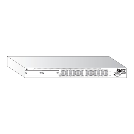
10/100 BOUT THE IGER WITCH Media Slots 10/100 Mbps RJ-45 Ports Port Status Indicators Module Indicators System Indicators Console Port Power Socket Figure 1-1. SMC6724L3 Front and Rear Panels Switch Architecture The switch employs a wire-speed, non-blocking switching fabric. This permits simultaneous wire-speed transport of multiple packets at low latency on all ports. -
Page 19: Management Options
VERVIEW Management Options This switch contains a comprehensive array of LEDs for “at-a-glance” monitoring of network and port status. It also includes a management agent that allows you to configure or monitor the switch using its embedded management software, or via SNMP applications. To manage the switch, you can make a direct connection to the RS-232 console port (out-of-band), or you can manage the switch through a network connection (in-band) using Telnet, the on-board Web agent, or... -
Page 20: Description Of Hardware
10/100 BOUT THE IGER WITCH Description of Hardware RJ-45 Ports The switch base unit contains 24 10BASE-T/100BASE-TX RJ-45 ports. All of these ports support automatic MDI/MDI-X operation, so you can use straight-through cables for all network connections to PCs or servers, or to other switches or hubs. -
Page 21: Ports Status Leds
ESCRIPTION OF ARDWARE Ports Status LEDs The LEDs, which are located on the front panel for easy viewing, are shown below and described in the following table. Module LEDs Link Activity Figure 1-2. Port Status LEDs Port and Status LEDs Condition Status Base Unit Ports... -
Page 22: System Status Leds
10/100 BOUT THE IGER WITCH System Status LEDs Figure 1-3. System Status LEDs System Status LEDs Condition Status Switch is receiving power. Power off or failure. The redundant power supply is operating normally. On Amber The redundant power supply has failed. No redundant power supply is connected. -
Page 23: Optional Media Extender Modules
ESCRIPTION OF ARDWARE Optional Media Extender Modules Optional 10/100/1000BASE-T Module (SMC6824GT) 10/100/1000BASE-T Gigabit Module SMC6824GT Figure 1-4. Single-Port 1000BASE-T Gigabit Module Using Category 5, 5e, or 6 twisted-pair cable you can connect to another device up to 100 m (328 ft) away. The 1000BASE-T module operates at 10/100/1000 Mbps. -
Page 24: Optional 100Base-Fx Module (Smc6824Fmsc)
10/100 BOUT THE IGER WITCH Optional 100BASE-FX Module (SMC6824FMSC) 100BASE-FX Multimode Module SMC6824FMSC Figure 1-6. Single-Port 100BASE-FX Multimode Module Using multimode fiber optic cable, the 100BASE-FX port can be connected to a remote site up to 2 km (1.24 miles) away. The 100BASE-FX module is fixed to operate at 100 Mbps full duplex, and supports auto-negotiation for flow control. -
Page 25: Optional Redundant Power Unit
ESCRIPTION OF ARDWARE connection. This port can be connected to a site up to 5 km (16404 ft) away with single-mode fiber cable. 1000BASE-ZX GBIC transceivers provide one long-wavelength (1550 nm) Gigabit port that can be used for a long-haul connection to a remote location. -
Page 26: Features And Benefits
10/100 BOUT THE IGER WITCH Features and Benefits Connectivity ◆ 24 dual-speed ports for easy Fast Ethernet integration and for protection of your investment in legacy LAN equipment. ◆ Auto-negotiation enables each RJ-45 port to automatically select the optimum communication mode (half or full duplex) if this feature is supported by the attached device;... -
Page 27: Performance
EATURES AND ENEFITS ◆ Optional single-port 1000BASE-T Gigabit module that can run up to 100 meters (using 100-ohm Category 5, 5e or 6 unshielded twisted-pair (UTP) or shielded twisted-pair (STP) cable), and operates at 1 Gbps, full duplex, with auto-negotiation for flow control. ◆... - Page 28 10/100 BOUT THE IGER WITCH • Spanning Tree Protocol for redundant network connections • VLAN support with up to 255 groups, port-based or with 802.1Q VLAN tagging, GVRP for automatic VLAN learning, and private VLANs • IP-based Layer 3 routing, OSPFv2 and DVMRP •...
-
Page 29: Network Planning
HAPTER ETWORK LANNING Introduction to Switching A network switch allows simultaneous transmission of multiple packets via non-crossbar switching. This means that it can partition a network more efficiently than bridges or routers. The switch has, therefore, been recognized as one of the most important building blocks for today's networking technology. -
Page 30: Application Examples
ETWORK LANNING Application Examples The TigerSwitch 10/100 is not only designed to segment your network, but also to provide a wide range of options in setting up network connections. Some typical applications are described below. Collapsed Backbone The TigerSwitch 10/100 is an excellent choice for mixed Ethernet and Fast Ethernet installations where significant growth is expected in the near future. -
Page 31: Central Wiring Closet
PPLICATION XAMPLES Central Wiring Closet With 26 parallel bridging ports (i.e., 26 distinct collision domains), this switch can collapse a complex network down into a single efficient bridged node, increasing overall bandwidth and throughput. In the figure below, the 10BASE-T/100BASE-TX ports on the switch are providing 100 Mbps connectivity for up to 24 segments. -
Page 32: Remote Connection With Fiber Cable
ETWORK LANNING Remote Connection with Fiber Cable Fiber optic technology allows for longer cabling than any other media type. A 100 Mbps multimode fiber (MMF) link can run up to 2 km, and a 100 Mbps single-mode fiber (SMF) link can run as far as 20 km. A 1000BASE-SX (MMF) link can connect to a site up to 550 meters away, and a 1000BASE-LX (SMF) link can run up to 70 km. -
Page 33: Making Vlan Connections
PPLICATION XAMPLES Making VLAN Connections VLANs can be based on port groups, or each data frame can be explicitly tagged to identify the VLAN group it belongs to. When using port-based VLANs, ports can either be assigned to one specific group or to all groups. Port-based VLANs are suitable for small networks. -
Page 34: Using Layer 3 Routing
ETWORK LANNING Using Layer 3 Routing VLANs can significantly enhance network performance and security. However, if you use conventional routers to interconnect VLANs, you can lose most of your performance advantage. The Fast Ethernet Routing Switch provides wire-speed routing, which allows you to eliminate your conventional IP routers, except for a router to handle non-IP protocols and a gateway router linked to the WAN. -
Page 35: Connectivity Rules
ONNECTIVITY ULES Connectivity Rules When adding hubs (repeaters) to your network, please follow the standard connectivity rules for Ethernet or Fast Ethernet. However, note that because switches break up the path for connected devices into separate collision domains, you should not include the switch or connected cabling in your calculations for cascade length involving other devices. -
Page 36: 10/100 Mbps Ethernet Collision Domain
ETWORK LANNING 10/100 Mbps Ethernet Collision Domain Maximum 10/100 Mbps Ethernet Cable Distance Type Cable Type Max. Cable Length 10BASE-T Twisted Pair, Category 3 or better 100 m (328 ft) 100BASE-TX Category 5 or better 100-ohm UTP or 100 m (328 ft) 100BASE-FX 50/125 or 62.5/125 micron core 2 km (1.24 miles) -
Page 37: Application Notes
PPLICATION OTES Application Notes 1. Full-duplex operation only applies to point-to-point access (such as when a switch is attached to a workstation, server or another switch). When the switch is connected to a hub, both devices must operate in half-duplex mode. 2. - Page 38 ETWORK LANNING 2-10...
-
Page 39: Installing The Switch
HAPTER NSTALLING THE WITCH Selecting a Site TigerSwitch 10/100 units can be mounted in a standard 19-inch equipment rack or on a flat surface. Be sure to follow the guidelines below when choosing a location. ◆ The site should: • be at the center of all the devices you want to link and near a power outlet. -
Page 40: Equipment Checklist
NSTALLING THE WITCH Equipment Checklist After unpacking the TigerSwitch 10/100, check the contents to be sure you have received all the components. Then, before beginning the installation, be sure you have all other necessary installation equipment. Package Contents ◆ TigerSwitch 10/100 unit, SMC6724L3 ◆... -
Page 41: Mounting
OUNTING Mounting A TigerSwitch 10/100 unit can be mounted in a standard 19-inch equipment rack or on a desktop or shelf. Mounting instructions for each type of site follow. Installing Optional Modules: Before mounting the switch, be sure you install any optional modules. If you have purchased optional slide-in 1000BASE-T, 100BASE-FX, or 1000BASE-X (GBIC) media expansion modules, install these modules now, following the instructions "Installing an Optional Module into the Switch"... - Page 42 NSTALLING THE WITCH To rack-mount devices: 1. Attach the brackets to the device using the screws provided in the Bracket Mounting Kit. Figure 3-1. Attaching the Brackets 2. Mount the device in the rack, using four rack-mounting screws (not provided). Figure 3-2.
-
Page 43: Desktop Or Shelf Mounting
OUNTING Desktop or Shelf Mounting 1. Attach the four adhesive feet to the bottom of the first switch. Figure 3-3. Attaching the Adhesive Feet 2. Set the device on a flat surface near an AC power source, making sure there are at least two inches of space on all sides for proper air flow. 3. -
Page 44: Installing An Optional Module Into The Switch
NSTALLING THE WITCH Installing an Optional Module into the Switch 1 0 0 B A S E -F X S in g le m o d e M o d u le Figure 3-4. Installing an Optional Module Caution: DO NOT install slide-in modules with the switch powered on. Be sure you power off the switch before installing any module. -
Page 45: Installing Agbic Transceiver
GBIC T NSTALLING A RANSCEIVER Installing a GBIC Transceiver 10 00 10 00 BA SE BA SE -X GB -X GB IC Mo IC Mo du le du le Figure 3-5. Installing a GBIC Transceiver You can install a GBIC transceiver as described below: 1. -
Page 46: Connecting To A Power Source
NSTALLING THE WITCH Connecting to a Power Source To connect a device to a power source: 1. Insert the power cable plug directly into the receptacle located at the back of the device. Figure 3-6. Power Receptacle 2. Plug the other end of the cable into a grounded, 3-pin socket. Note: For International use, you may need to change the AC line cord. -
Page 47: Making Network Connections
HAPTER AKING ETWORK ONNECTIONS Connecting Network Devices The TigerSwitch 10/100 may be connected to 10 or 100 Mbps network cards in PCs and servers, as well as to hubs and switches. It may also be connected to remote devices using the optional fiber optic modules Twisted-Pair Devices Each device requires a shielded or unshielded twisted-pair (STP or UTP) cable with RJ-45 connectors at both ends. -
Page 48: Connecting To Pcs, Servers, Hubs And Switches
AKING ETWORK ONNECTIONS MDI-X port using straight-through cable. To connect between two switches/hubs that only have fixed MDI-X ports, the wiring crossover must be implemented in the cable - known as a crossover cable. The RJ-45 ports on the switch base unit support automatic MDI/MDI-X operation, which means that they automatically detect the wiring in the link and configure as MDI or MDI-X accordingly. - Page 49 WISTED EVICES 2. If the device is a PC card and the switch is in the wiring closet, attach the other end of the cable segment to a modular wall outlet that is connected to the wiring closet (See “Wiring Closet Connections” on the next page.) Otherwise, attach the other end to an available port on the switch.
-
Page 50: Wiring Closet Connections
AKING ETWORK ONNECTIONS Wiring Closet Connections Today, the punch-down block is an integral part of many of the newer equipment racks. It is actually part of the patch panel. Instructions for making connections in the wiring closet with this type of equipment follows. -
Page 51: Fiber Optic Devices
IBER PTIC EVICES Fiber Optic Devices An optional slide-in 100BASE-FX module or 1000BASE-X (GBIC) transceiver may be used for backbone and long-distance connections. A 1000BASE-SX, 100BASE-LX, or 1000BASE-ZX GBIC transceiver may also be used for connecting to a high-speed server. Each multimode fiber optic port requires 50/125 or 62.5/125 micron multimode fiber optic cabling with an SC connector at both ends. - Page 52 AKING ETWORK ONNECTIONS 3. Connect one end of the cable to the SC port on the switch and the other end to the SC port on the other device. Since SC connectors are keyed, the cable can be attached in only one orientation. SC fiber connector Figure 4-3.
-
Page 53: Troubleshooting
PPENDIX ROUBLESHOOTING Diagnosing Switch Indicators Troubleshooting Chart Symptom Action PWR LED is Off • Internal power supply has failed or is disconnected. • Check connections between the switch, the power cord, and the wall outlet. • Check connections between the switch, the power cord, the wall outlet.Contact SMC Technical Support. -
Page 54: Power And Cooling Problems
ROUBLESHOOTING Power and Cooling Problems If the power indicator does not turn on when the power cord is plugged in, you may have a problem with the power outlet, power cord, or internal power supply. However, if the unit powers off after running for a while, check for loose power connections, power losses or surges at the power outlet, and verify that the fans on the unit are unobstructed and running prior to shutdown. -
Page 55: Cables
PPENDIX ABLES Specifications Cable Types and Specifications Cable Type Max. Length Connector 10BASE-T Cat. 3 or better 100-ohm 100 m (328 ft) RJ-45 100BASE-TX Cat 5 or better 100-ohm 100 m (328 ft) RJ-45 100BASE-FX 50/125 or 62.5/125 micron 2 km (1.24 miles) SC or ST core multimode fiber (MMF) 100BASE-FX 9/125 micron core... -
Page 56: Twisted-Pair Cable And Pin Assignments
ABLES Note: If you need to connect to a device with 62.5/125 micron cable that has ST-type connectors, SMC provides an optional SC-ST Converter (Part Number: 99-012034-091). Twisted-Pair Cable and Pin Assignments Caution: DO NOT plug a phone jack connector into any RJ-45 port. Use only twisted-pair cables with RJ-45 connectors that conform with FCC standards. - Page 57 WISTED ABLE AND SSIGNMENTS RJ-45 connections: 100-ohm Category 3, 4 or 5 cable for 10 Mbps connections or 100-ohm Category 5 cable for 100 Mbps connections. Also be sure that the length of any twisted-pair connection does not exceed 100 meters (328 feet).
-
Page 58: Straight-Through Wiring
ABLES Straight-Through Wiring If the twisted-pair cable is to join two ports and only one of the ports has an internal crossover (MDI-X), the two pairs of wires must be straight-through. (When auto-negotiation is enabled for any RJ-45 port on this switch, you can use either straight-through or crossover cable to connect to any device type). -
Page 59: 1000Base-T Pin Assignments
WISTED ABLE AND SSIGNMENTS 1000BASE-T Pin Assignments 1000BASE-T ports switch support automatic MDI/MDI-X operation, so you can use straight-through cables for all network connections to PCs or servers, or to other switches or hubs. The table below shows the 1000BASE-T MDI and MDI-X port pinouts. These ports require that all four pairs of wires be connected. -
Page 60: 1000Base-T Cable Requirements
ABLES 1000BASE-T Cable Requirements All Category 5 UTP cables that are used for 100BASE-TX connections should also work for 1000BASE-T, providing that all four wire pairs are connected. However, it is recommended that for all critical connections, or any new cable installations, Category 5e (enhanced Category 5) or 6 cable should be used. -
Page 61: Console Port Pin Assignments
ONSOLE SSIGNMENTS Console Port Pin Assignments The DB-9 serial port on the switch’s front panel is used to connect to the switch for out-of-band console configuration. The on-board menu-driven configuration program can be accessed from a terminal or a PC running a terminal emulation program. -
Page 62: Console Port To 25-Pin Dte Port On Pc
ABLES Console Port to 25-Pin DTE Port on PC Switch’s 9-Pin Null Modem PC’s 25-Pin Serial Port DTE Port 2 RXD <---------TXD ------------ 2 TXD 3 TXD -----------RXD ----------> 3 RXD 5 SGND -----------SGND ---------- 7 SGND No other pins are used. -
Page 63: Specifications
PPENDIX PECIFICATIONS Physical Characteristics Base Unit Ports 24 10BASE-T/100BASE-TX, with auto-negotiation Media Slot 2 slots for optional 100BASE-FX, 1000BASE-T and 1000BASE-X (GBIC) Network Interface 10BASE-T: RJ-45 (100-ohm, UTP cable; Categories 3, 4, 5) 100BASE-TX: RJ-45 (100-ohm, UTP cable; Category 5) Ports 1-24: RJ-45 connectors, auto MDI/MDI-X Communication Speed 10 and 100 Mbps... -
Page 64: Switch Features
PECIFICATIONS LEDs System: PWR, RPU, Diag Port: Link/Activity Weight 5.0 kg (11.02 oz) Size 44.0 x 41.0 x 4.4 cm (17.4 x 17.3 x 1.7 in.) Temperature ° ° Operating: 0 to 50 C (32 to 122 ° ° Storage: -40 to 70 C (-40 to 158 Humidity Operating: 5% to 95%... -
Page 65: Management Features
ANAGEMENT EATURES Half Duplex: Back pressure Broadcast Storm Suppression Traffic throttled above a critical threshold VLAN Support Up to 255 groups; port-based or with 802.1Q VLAN tagging, GVRP for automatic VLAN learning, private VLANs Multicast Switching IGMP Snooping Quality of Service Supports four levels of priority and Weighted Round Robin Queueing (which can be configured by VLAN tag or port), Layer 3/4 priority mapping: IP Precedence, IP DSCP... -
Page 66: Standards
PECIFICATIONS Standards IEEE 802.3 Ethernet, IEEE 802.3u Fast Ethernet IEEE 802.1p priority tags IEEE 802.3ac VLAN tagging IEEE 802.1Q VLAN Bridge Management IEEE 802.3x full-duplex flow control ISO/IEC 8802-3 SNMP (RFC 1157), ARP (RFC 826), MIB II (RFC 1213), Bridge MIB (RFC 1493) Compliances CE Mark... -
Page 67: Slide-In Modules
LIDE ODULES Slide-in Modules 100BASE-FX Extender Modules Models SMC6824FSSC, SMC6824FMSC Ports 1 100BASE-FX, SC connectors Communication Speed 100 Mbps Communication Mode Full duplex Network Interface SMC6824FSSC 9/125 micron single-mode fiber cable SMC6824FMSC 50/125 or 62.5/125 micron multimode fiber cable Standards IEEE 802.3u Fast Ethernet ISO/IEC 8802-3 1000BASE-T Extender Module... -
Page 68: 1000Base-X Gbic Module
PECIFICATIONS Full and half duplex at 10/100 Mbps Network Interface RJ-45 (100-ohm, UTP cable; Category 5, 5e, or 6) Standards IEEE 802.3ab Gigabit Ethernet IEEE 802.3u Fast Ethernet IEEE 802.3 Ethernet 1000BASE-X GBIC Module Model SMC6824GB Ports 1 slot for GBIC transceivers Communication Speed 1000 Mbps Communication Mode... - Page 69 PPENDIX RDERING NFORMATION TigerSwitch 10/100 Products and Accessories Product Number Description SMC6724L3 24-port Fast Ethernet switch with two media expansion slots SMC6824GT Gigabit module with one 10/100/1000BASE-T port (RJ-45 connector) SMC6824FSSC Extender module with one 100BASE-FX single-mode fiber port (SC-type connector) SMC6824FMSC Extender module with one 100BASE-FX multimode fiber port (SC-type connector)
-
Page 70: Ordering Information
RDERING NFORMATION... - Page 71 LOSSARY 10BASE-T IEEE 802.3 specification for 10 Mbps Ethernet over two pairs of Category 3, 4, or 5 UTP cable. 100BASE-TX IEEE 802.3u specification for 100 Mbps Fast Ethernet over two pairs of Category 5 UTP cable. 100BASE-FX IEEE 802.3u specification for 100 Mbps Fast Ethernet over two strands of 50/125 or 62.5/125 micron core fiber cable.
- Page 72 Auto-Negotiation Signalling method allowing each node to select its optimum operational mode (e.g., 10, 100, or 1000 Mbps and half or full duplex) based on the capabilities of the node to which it is connected. Bandwidth The difference between the highest and lowest frequencies available for network signals.
-
Page 73: Gigabit Ethernet
Fast Ethernet A 100 Mbps network communication system based on Ethernet and the CSMA/CD access method. Fast Ethernet Switch Device that provides a full 100 Mbps bandwidth (or either 10 or 100 Mbps bandwidth with Auto-Negotiation) to each port (LAN segment). Full Duplex Transmission method that allows switch and network card to transmit and receive concurrently, effectively doubling the bandwidth of that link. - Page 74 IEEE 802.3ab Defines CSMA/CD access method and physical layer specifications for 1000BASE-T Gigabit Ethernet. IEEE 802.3u Defines CSMA/CD access method and physical layer specifications for 100BASE-TX and 100BASE-FX Fast Ethernet. IEEE 802.3x Defines Ethernet frame start/stop requests and timers used for flow control on full-duplex links.
- Page 75 An acronym for Management Information Base. It is a set of database objects that contains information about the device. Media Independent Interface, the standard interface for Fast Ethernet—similar to the AUI interface for traditional Ethernet. Network Diameter Wire distance between two end stations in the same collision domain. RJ-45 Connector A connector for twisted-pair wiring.
- Page 76 Glossary-6...
- Page 77 NDEX Numerics VLAN connections 2-3 10 Mbps connectivity rules 2-9 10/100 Mbps connectivity rules 2-8 10/100/1000BASE-T brackets, attaching 3-4 modules 1-7 buffer size C-1 1000 Mbps connectivity rules 2-7 1000BASE-LX connections 4-5 fiber cable lengths 2-7 cable 1000BASE-SX lengths 2-7 connections 4-5 specifications B-1 fiber cable lengths 2-7...
- Page 78 NDEX features C-3 management management 1-11 agent 1-3 switch 1-10 features 1-11 fiber cables 4-5 out-of-band 1-3 front and rear panels of switch 1-2 SNMP 1-3 full-duplex connectivity 2-1 Web-based 1-3 MIB support C-3 modules 10/100/1000BASE-T 1-7 1000BASE-SX 1-8 Gigabit Ethernet cable lengths 2-7 1000BASE-X 1-8 grounding for racks 3-3 100BASE-FX 1-7...
- Page 79 NDEX 100BASE-TX/10BASE-T B-2 switch architecture 1-2 25-pin DTE port B-8 switching, introduction to 2-1 DB-9 B-7 port saturation 1-3 port-based VLANs 2-5 ports, connecting to 4-1 tagging 2-5 power, connecting to 3-8 temperature within a rack 3-3 problems, troubleshooting A-1 troubleshooting in-band access A-2 power and cooling problems A-2...
- Page 80 NDEX Index-4...
- Page 82 FOR TECHNICAL SUPPORT, CALL: From U.S.A. and Canada (24 hours a day, 7 days a week) (800) SMC-4-YOU; (949) 679-8000; Fax: (949) 679-1481 From Europe (8:00 AM - 5:30 PM UK Time) 44 (0) 118 974 8700; Fax: 44 (0) 118 974 8701 INTERNET E-mail addresses: techsupport@smc.com...
Need help?
Do you have a question about the TigerSwitch 100 SMC6724L3 and is the answer not in the manual?
Questions and answers