Table of Contents
Advertisement
Quick Links
Advertisement
Table of Contents

Related Manuals for Asus F2A85-M PRO


Summary of Contents for Asus F2A85-M PRO
- Page 1 F2A85-M PRO...
- Page 2 Product warranty or service will not be extended if: (1) the product is repaired, modiied or altered, unless such repair, modiication of alteration is authorized in writing by ASUS; or (2) the serial number of the product is defaced or missing.
-
Page 3: Table Of Contents
Contents Safety information ..................... vii About this guide ....................... viii F2A85-M PRO speciications summary ..............x Package contents ..................... xiv Installation tools and components ................xv Product introduction Special features..................1-1 1.1.1 Product highlights................ 1-1 1.1.2 Dual Intelligent Processors 2 – DIGI+ VRM ........ 1-2 1.1.3... - Page 4 BIOS setup Knowing BIOS .................... 3-1 BIOS setup program .................. 3-2 3.2.1 EZ Mode..................3-3 3.2.2 Advanced Mode ................3-4 Main menu ....................3-6 Ai Tweaker menu ..................3-8 3.4.1 Ai Overclock Tuner [Auto] ............3-9 3.4.2 Memory Frequency [Auto] ............3-9 3.4.3 APU Multiplier [Auto] ..............
- Page 5 3.7.12 Boot Option Priorities ..............3-26 3.7.13 Boot Override ................3-26 Tools menu ....................3-27 3.8.1 ASUS EZ Flash 2 Utility ............3-27 3.8.2 ASUS SPD Information ............. 3-27 3.8.3 ASUS O.C. Proile ..............3-27 Exit menu ....................3-28 Software support Installing an operating system ..............
- Page 6 CATALYST Control Center ......6-6 LucidLogix Virtu MVP ................6-8 6.3.1 Installing LucidLogix Virtu MVP ........... 6-8 6.3.2 Setting up your display ..............6-9 6.3.3 Coniguring LucidLogix Virtu MVP ..........6-10 Appendices Notices ........................A-1 ASUS contact information ..................A-4...
-
Page 7: Safety Information
Safety information Electrical safety To prevent electrical shock hazard, disconnect the power cable from the electrical outlet • before relocating the system. • When adding or removing devices to or from the system, ensure that the power cables for the devices are unplugged before the signal cables are connected. If possible, disconnect all power cables from the existing system before you add a device. -
Page 8: About This Guide
Refer to the following sources for additional information and for product and software updates. ASUS websites The ASUS website provides updated information on ASUS hardware and software products. Refer to the ASUS contact information. Optional documentation Your product package may include optional documentation, such as warranty lyers, that may have been added by your dealer. -
Page 9: Conventions Used In This Guide
Conventions used in this guide To ensure that you perform certain tasks properly, take note of the following symbols used throughout this manual. DANGER/WARNING: Information to prevent injury to yourself when trying to complete a task. CAUTION: Information to prevent damage to the components when trying to complete a task IMPORTANT: Instructions that you MUST follow to complete a task. -
Page 10: F2A85-M Pro Speciications Summary
DDR3 2400(O.C.)/1866/1600/1333/1066 MHz memory modules • The maximum 64GB memory capacity can be supported with 16GB or above DIMMs. ASUS will update the memory QVL once the DIMMs are available in the market. • Refer to www.asus.com for the latest Memory QVL (Qualiied Vendors List). - Page 11 - 2 x USB 3.0 ports (blue, at the back panel) * Supports ASUS USB 3.0 Boost UASP Mode ASUS unique features ASUS Dual Intelligent Processors II – TPU & EPU - Auto Tuning, TurboV, EPU and TPU switch ASUS Digital Power Design...
- Page 12 SFS (Stepless Frequency Selection): - APU frequency tuning from 90MHz up to 300MHz at 1MHz increment Overclocking Protection: - ASUS C.P.R (CPU Parameter Recall) Internal I/O connectors / 4 x USB 2.0 connectors support additional 8 USB ports buttons / switches 1 x USB 3.0 connector supports additional 2 USB ports...
- Page 13 F2A85-M PRO speciications summary BIOS 64Mb Flash ROM, UEFI BIOS, PnP, DMI 2.0, WfM 2.0, SM BIOS V2.7, ACPI 2.0a Accessories 2 x Serial ATA 6.0Gb/s cables 1 x Q-Shield 1 x User Manual 1 x Support DVD Support DVD...
-
Page 14: Package Contents
Package contents Check your motherboard package for the following items. F2A85-M PRO ASUS F2A85-M PRO motherboard User Guide Support DVD 2 x Serial ATA 6.0 Gb/s cables 1 x ASUS Q-Shield • If any of the above items is damaged or missing, contact your retailer. -
Page 15: Installation Tools And Components
Installation tools and components Philips (cross) screwdriver 1 bag of screws PC chassis Power supply unit AMD FM2 APU AMD FM2 compatible CPU Fan DIMM SATA hard disk drive SATA optical disc drive (optional) Graphics card (optional) The tools and components in the table above are not included in the motherboard package. -
Page 17: Product Introduction
6.0 Gb/s data transfer rates. It also provides enhanced scalability, faster data retrieval, double the bandwidth of current bus systems. 100% All High-quality Conductive Polymer Capacitors This motherboard uses all high-quality conductive polymer capacitors for durability, improved lifespan, and enhanced thermal capacity. F2A85-M PRO... -
Page 18: Dual Intelligent Processors 2 - Digi+ Vrm
ASUS TurboV With its user-friendly interface, ASUS TurboV offers you the adrenaline rush of real-time overclocking without exiting or rebooting the OS. It also provides you with the ASUS OC proiles for the best overclocking settings in different scenarios. Auto Tuning Auto Tuning is an intelligent tool that automates overclocking to achieve a total system level up. - Page 19 Ai Charger+ ASUS Ai Charger+, the latest Ai Charger* version, brings you to a new level of USB3.0 fast charging experience. With its easy and user-friendly interface, you can easily charge iPod, iPhone, iPad, but also BC 1.1** standard mobile devices three times*** as fast as before.
-
Page 20: Asus Mylogo 2
Electronic Magnetic Interference (EMI). ASUS EZ Flash 2 ASUS EZ Flash 2 is a user-friendly utility that allows you to update the BIOS without using a bootable loppy disk or an OS-based utility. ASUS MyLogo 2™... -
Page 21: Motherboard Overview
• Before you install or remove any component, switch off the ATX power supply and detach its power cord. Failure to do so may cause severe damage to the motherboard, peripherals, or components. F2A85-M PRO... -
Page 22: Motherboard Layout
KBMS_USB12 CPU_FAN EPU_LED SPDIFO _HDMI EATX12V 1445 ESATA6G _USB3 CHA_FAN3 _USB3 _E12 1042 Lithium Cell AUDIO CMOS Power PCIEX16_1 8111F F2A85-M PRO PCIEX1_1 ® Super A85X PCIEX1_2 64Mb BIOS SB_PWR PCIEX16_2 CLRTC FLBK_LED SPDIF_OUT TPU_LED CHA_FAN2 COM1 USB910 BIOS_FLBK USB78... -
Page 23: Layout Contents
20. TPM connector (20-1 pin TPM) 1-31 21. Serial port connector (10-1 pin COM1) 1-27 22. Front panel audio connector (10-1 pin AAFP) 1-29 23. Digital audio connector (4-1 pin SPDIF_OUT) 1-27 24. Standby power LED (SB_PWR) 1-22 F2A85-M PRO... -
Page 24: System Memory
DDR2 DIMM socket. DDR3 modules are developed for better performance with less power consumption. The igure illustrates the location of the DDR3 DIMM sockets: F2A85-M PRO F2A85-M PRO 240-pin DDR3 DIMM sockets Recommended memory conigurations Chapter 1: Product introduction... - Page 25 • The maximum 64GB memory capacity can be supported with 16GB or above DIMMs. ASUS will update the memory QVL once the DIMMs are available in the market. • The default memory operation frequency is dependent on its Serial Presence Detect (SPD), which is the standard way of accessing information from a memory module.
- Page 26 F2A85-M PRO Motherboard Qualiied Vendors Lists (QVL) DDR3 2400(O.C.) MHz capability DIMM socket support (Optional) Vendors Part No. Size DS Chip Brand Chip NO. Timing Voltage 1 DIMM 2 DIMMs 4 DIMMs F3-19200CL9D- G.SKILL (2x 2GB) DS - 9-11-9-28 1.65V •...
- Page 27 • • CORSAIR CMZ8GX3M2A1600C7R(XMP) 8GB(2x4GB) 7-8-7-20 1.50V • • • CORSAIR CMX8GX3M4A1600C9(XMP) 8GB(4x2GB) 9-9-9-24 1.65V • • • Crucial BL25664BN1608.16FF(XMP) 6GB(3x2GB) • • • G.SKILL F3-12800CL9D-2GBNQ(XMP) 2GB(2x1GB) 9-9-9-24 1.5V • • • (continued on the next page) F2A85-M PRO 1-11...
- Page 28 DDR3 1600 MHz capability DIMM socket support (Optional) Vendors Part No. Size Chip Brand Chip NO. Timing Voltage DIMM DIMMs DIMMs G.SKILL F3-12800CL7D-4GBRH(XMP) 4GB(2x2GB) 7-7-7-24 1.6V • • • G.SKILL F3-12800CL7D-4GBECO(XMP) 4GB(2x2GB) 7-7-8-24 • • • 1.35V G.SKILL F3-12800CL7D-4GBRM(XMP) 4GB(2x2GB) 7-8-7-24 1.6V •...
- Page 29 IID77 D9LGK 1.5V • • • KVR1333D3S8N9/2G-SP(Low KINGSTON ELPIDA J2108BCSE-DJ-F 1.5V • • • proile) KVR1333D3N9/2G(Low proile) 2GB KINGSTON ELPIDA J1108BFBG-DJ-F 1.5V • • • KINGSTON KVR1333D3N9/2G D1288JPNDPLD9U 1.5V • • • (continued on the next page) F2A85-M PRO 1-13...
- Page 30 DDR3 1333 MHz capability DIMM socket support (Optional) Vendors Part No. Size Chip Brand Chip NO. Timing Voltage 1 DIMM DIMMs DIMMs KINGSTON KVR1333D3N9/2G ELPIDA J1108BDSE-DJ-F 1.5V • • • KVR1333D3N9/2G-SP(Low KINGSTON D1288JEMFNGD9U 1.5V • • • proile) KVR1333D3N9/2G-SP(low KINGSTON KINGSTON D1288JPSFPGD9U 1.5V...
- Page 31 (4) Supports four (4) modules inserted into both the blue and black slots as two pairs of Dual-channel memory coniguration. • When overclocking, some AMD CPU models may not support DDR3 1600 or higher frequency DIMMS. • Visit the ASUS website for the latest QVL. F2A85-M PRO 1-15...
-
Page 32: Expansion Slots
1.2.4 Expansion slots Unplug the power cord before adding or removing expansion cards. Failure to do so may cause you physical injury and damage motherboard components. F2A85-M PRO 64Mb BIOS SB_PWR Slot No. Slot Description PCIe 2.0 x16_1 slot (Single @x16 or dual@x8x8 mode) PCIe 2.0 x1_1 slot... -
Page 33: Irq Assignments For This Motherboard
USB 3.0_1 shared USB 3.0_2 shared Realtek 8111F (LAN) shared On Chip SATA shared On Chip USB_1 shared On Chip USB_2 shared On Chip USB_3 shared On Chip USB_4 shared On Chip USB_5 shared HD Audio shared F2A85-M PRO 1-17... -
Page 34: Onboard Switches And Buttons
<Delete> key during POST. It allows you to turn on or turn off the system and conveniently enter the BIOS during bootup. DirectKey F2A85-M PRO F2A85-M PRO DirectKey button Ensure to save your data before using the DirectKey button. • When the system is on and you press the DirectKey button, your system will shut down. - Page 35 BIOS default settings. A message will appear during POST reminding you that the BIOS has been restored to its default settings. • We recommend that you download and update to the latest BIOS version from the ASUS website at www.asus.com after using the MemOK! function. F2A85-M PRO 1-19...
- Page 36 USB port, press the BIOS Flashback button, and the BIOS is updated automatically. BIOS_FLBK F2A85-M PRO F2A85-M PRO BIOS FLBK button For more details about using the USB BIOS Flashback button, refer to section 2.2.1 USB BIOS Flashback. 1-20...
-
Page 37: Jumpers
Normal Clear RTC (Default) F2A85-M PRO Clear RTC RAM To erase the RTC RAM: Turn OFF the computer and unplug the power cord. Move the jumper cap from pins 1-2 (default) to pins 2-3. Keep the cap on pins 2-3 for about 5~10 seconds, then move the cap back to pins 1-2. -
Page 38: Onboard Leds
This user-friendly design provides an intuitional way to locate the root problem within a second. DRAM LED F2A85-M PRO F2A85-M PRO DRAM LED TPU LED The TPU LED lights when the TPU switch is turned to Enable. F2A85-M PRO TPU_LED F2A85-M PRO TPU Boost LED 1-22 Chapter 1: Product introduction... - Page 39 The EPU LED lights when the EPU switch is turned to Enable. EPU_LED F2A85-M PRO F2A85-M PRO EPU Boost LED BIOS Flashback LED (FLBK_LED) The FLBK LED lights when the USB Flashback button is pressed for three seconds. F2A85-M PRO...
-
Page 40: Internal Connectors
• The CPU_FAN connector supports a CPU fan of maximum 2A (24 W) fan power. • Only the CPU_FAN and CHA_FAN1/2/3 connectors support the ASUS Fan Xpert 2 feature. • If you install two VGA cards, we recommend that you plug the rear chassis fan cable to the motherboard connector labeled CHA_FAN1/2 for better thermal environment. - Page 41 The system may become unstable or may not boot up if the power is inadequate. • If you are uncertain about the minimum power supply requirement for your system, refer to the Recommended Power Supply Wattage Calculator at http://support.asus. com/PowerSupplyCalculator/PSCalculator.aspx?SLanguage=en-us for details. F2A85-M PRO 1-25...
- Page 42 SATA6G_1 SATA6G_2 F2A85-M PRO F2A85-M PRO SATA 6.0Gb/s connectors • These connectors are set to AHCI mode by default. In AHCI mode, you can connect Serial ATA boot/data hard disk drives to these connectors. If you intend to create a Serial ATA RAID set using these connectors, set the type of the SATA connectors in the BIOS to [RAID].
- Page 43 COM1 PIN 1 F2A85-M PRO F2A85-M PRO Serial port (COM1) connector The COM module is purchased separately. Digital audio connector (4-1 pin SPDIF_OUT) This connector is for an additional Sony/Philips Digital Interface (S/PDIF) port.
-
Page 44: System Panel Connector
IDE_LED PWRSW RESET * Requires an ATX power supply F2A85-M PRO System panel connector • System power LED (2-pin PLED) This 2-pin connector is for the system power LED. Connect the chassis power LED cable to this connector. The system power LED lights up when you turn on the system power, and blinks when the system is in sleep mode. - Page 45 This connector is for the additional USB 3.0 ports. Connect the USB 3.0 bracket cable to this connector, then install the USB 3.0 bracket to the rear side of the chassis. If your chassis support customized front panel installation, with ASUS USB 3.0 header, you can have a front panel USB 3.0 solution.
- Page 46 PIN 1 PIN 1 PIN 1 PIN 1 F2A85-M PRO F2A85-M PRO USB2.0 connectors Never connect a 1394 cable to the USB connectors. Doing so will damage the motherboard! The USB 2.0 module is purchased separately. Direct connector (2-pin DRCT) This connector is for the chassis-mounted button that supports the DirectKey function.
- Page 47 This connector supports a Trusted Platform Module (TPM) system, which securely store keys, digital certiicates, passwords and data. A TPM system also helps enhance network security, protect digital identities, and ensures platform integrity. F2A85-M PRO F2A85-M PRO TPM connector TPM module is purchased separately. F2A85-M PRO 1-31...
- Page 48 1-32 Chapter 1: Product introduction...
-
Page 49: Basic Installation
Motherboard installation The diagrams in this section are for reference only. The motherboard layout may vary with models, but the installation steps are the same for all models. Install the ASUS Q-Shield to the chassis rear I/O panel. ASUS F2A85-M PRO... - Page 50 Place the motherboard into the chassis, ensuring that its rear I/O ports are aligned to the chassis’ rear I/O panel. Chapter 2: Basic installation...
- Page 51 Place nine screws into the holes indicated by circles to secure the motherboard to the chassis. F2A85-M PRO DO NOT overtighten the screws! Doing so can damage the motherboard. ASUS F2A85-M PRO...
-
Page 52: Apu Installation
2.1.2 APU installation The AMD FM2 socket is compatible with AMD A-series accelerated processors. Ensure that you use a CPU designed for the FM2 socket. The CPU its in only one correct orientation. DO NOT force the APU into the socket to prevent bending the connectors on the socket and damaging the APU! Chapter 2: Basic installation... -
Page 53: Cpu Heatsink And Fan Assembly Installation
2.1.3 CPU heatsink and fan assembly installation Apply the Thermal Interface Material to the CPU heatsink and CPU before you install the heatsink and fan if necessary. ASUS F2A85-M PRO... - Page 54 To install the CPU heatsink and fan assembly Chapter 2: Basic installation...
- Page 55 ASUS F2A85-M PRO...
-
Page 56: Dimm Installation
2.1.4 DIMM installation To remove a DIMM Chapter 2: Basic installation... -
Page 57: Atx Power Connection
2.1.5 ATX Power connection ASUS F2A85-M PRO... -
Page 58: Sata Device Connection
2.1.6 SATA device connection 2-10 Chapter 2: Basic installation... -
Page 59: Expansion Card Installation
2.1.7 Expansion Card installation To install PCIe x16 cards To install PCIe x1 cards ASUS F2A85-M PRO 2-11... -
Page 60: Bios Update Utility
• Updating BIOS may have risks. If the BIOS program is damaged during the process and results to the system’s failure to boot up, please contact your local ASUS Service Center. 2-12... -
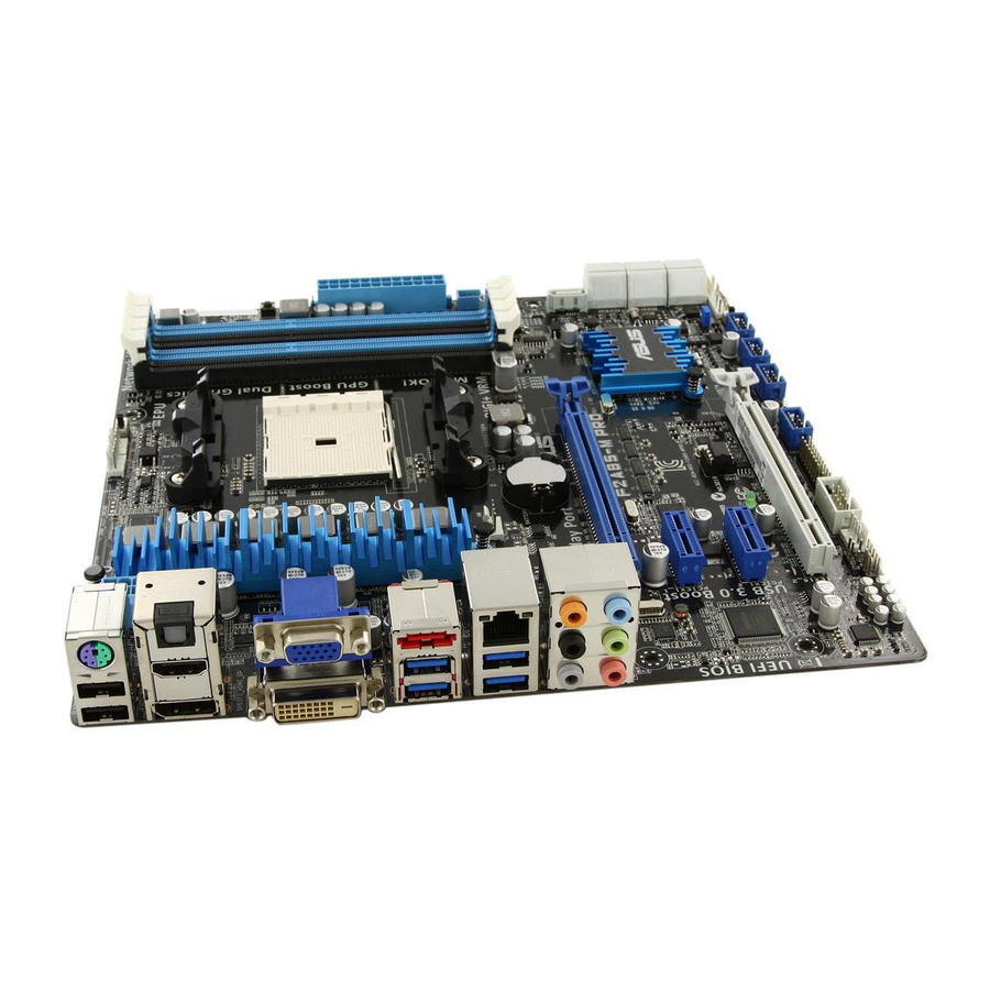
Page 61: Motherboard Rear And Audio Connections
Motherboard rear and audio connections 2.3.1 Rear I/O connection Rear panel connectors AMD USB 3.0 ports 1 and 2 support ASUS USB 3.0 Boost UASP Mode. PS/2 keyboard/mouse combo port Bottom part supports USB BIOS Flashback and USB Charger+ Optical S/PDIF Out port... - Page 62 • DO NOT insert a different connector to the external SATA port. • Due to USB 3.0 controller limitation, USB 3.0 devices can only be used under ® Windows OS environment and after the USB 3.0 driver installation. • USB 3.0 devices can only be used as data storage only. •...
-
Page 63: Audio I/O Connections
2.3.2 Audio I/O connections Audio I/O ports Connect to Headphone and Mic Connect to Stereo Speakers Connect to 2.1 channel Speakers ASUS F2A85-M PRO 2-15... - Page 64 Connect to 4.1 channel Speakers Connect to 5.1 channel Speakers Connect to 7.1 channel Speakers 2-16 Chapter 2: Basic installation...
-
Page 65: Starting Up For The Irst Time
While the system is ON, press the power button for less than four seconds to put the system on sleep mode or soft-off mode, depending on the BIOS setting. Press the power switch for more than four seconds to let the system enter the soft-off mode regardless of the BIOS setting. ASUS F2A85-M PRO 2-17... - Page 66 2-18 Chapter 2: Basic installation...
-
Page 67: Bios Setup
BIOS setup Knowing BIOS The new ASUS UEFI BIOS is a Uniied Extensible Interface that complies with UEFI architecture, offering a user-friendly interface that goes beyond the traditional keyboard- only BIOS controls to enable a more lexible and convenient mouse input. You can easily navigate the new UEFI BIOS with the same smoothness as your operating system. -
Page 68: Bios Setup Program
BIOS setup program Use the BIOS Setup to update the BIOS or conigure its parameters. The BIOS screen include navigation keys and brief onscreen help to guide you in using the BIOS Setup program. Entering BIOS at startup To enter BIOS Setup at startup: •... -
Page 69: Ez Mode
• The boot device options vary depending on the devices you installed to the system. The Boot Menu(F8) button is available only when the boot device is installed to the • system. ASUS F2A85-M PRO... -
Page 70: Advanced Mode
3.2.2 Advanced Mode The Advanced Mode provides advanced options for experienced end-users to conigure the BIOS settings. The igure below shows an example of the Advanced Mode. Refer to the following sections for the detailed conigurations. To access the Advanced Mode, click Exit, then select Advanced Mode or press F7 hotkey. Coniguration ields Menu items Menu bar... -
Page 71: Menu Items
You cannot select an item that is not user-conigurable. A conigurable ield is highlighted when selected. To change the value of a ield, select it and press <Enter> to display a list of options. ASUS F2A85-M PRO... -
Page 72: Main Menu
Main menu The Main menu screen appears when you enter the Advanced Mode of the BIOS Setup program. The Main menu provides you an overview of the basic system information, and allows you to set the system date, time, language, and security settings. Security The Security menu items allow you to change the system security settings. -
Page 73: Administrator Password
The User Password item on top of the screen shows the default Not Installed. After you set a password, this item shows Installed. To set a user password: Select the User Password item and press <Enter>. From the Create New Password box, key in a password, then press <Enter>. Conirm the password when prompted. ASUS F2A85-M PRO... -
Page 74: Ai Tweaker Menu
To change a user password: Select the User Password item and press <Enter>. From the Enter Current Password box, key in the current password, then press <Enter>. From the Create New Password box, key in a new password, then press <Enter>. Conirm the password when prompted. -
Page 75: Ai Overclock Tuner [Auto]
This item appears only when The EPU Power Saving Mode is set to [Enabled] and allows you to set power saving mode. Coniguration options: [Auto] [Light Power Saving Mode] [Medium Power Saving Mode] [Max Power Saving Mode] ASUS F2A85-M PRO... -
Page 76: Gpu Boost
3.4.6 GPU Boost Allows you to conigure the GPU Boost settings. [Auto] GPU is set to its optimized settings. [Turbo] Select to achieve better 3D performance. [Extreme] Select to get an excellent visual performance. [Manual] Select to manually set your preferred value. 3.4.7 OC Tuner OC Tuner automatically overclocks the frequency and voltage of CPU and DRAM for... -
Page 77: Cpu Voltage [Offset Mode]
VRM eficiency. [Standard] Proceeds phase control depending on the CPU loading. [Optimized] Loads the ASUS optimized phase tuning proile. [Extreme] Proceeds the full phase mode. [Manual Adjustment] Allows manual adjustment. CPU Voltage Frequency [Auto] Switching frequency will affect the VRM transient response and component thermal. -
Page 78: Dram Voltage [Auto]
VDDNB Offset Mode Sign [+] This item appears only when you set the CPU Voltage item to [Offset Mode]. To offset the voltage by a positive value. [–] To offset the voltage by a negative value. VDDNB Offset Voltage [Auto] Allows you to set the VDDNB Offset voltage. -
Page 79: Dram Vrefdq Voltage [Auto]
• The system may need better cooling system to work stably under high voltage settings. 3.4.19 CPU Spread Spectrum [Auto] [Auto] Automatic coniguration. [Disabled] Enhances the BCLK overclocking ability. [Enabled] Sets to [Enabled] for EMI control. ASUS F2A85-M PRO 3-13... -
Page 80: Advanced Menu
Advanced menu The Advanced menu items allow you to change the settings for the CPU and other system devices. Be cautious when changing the settings of the Advanced menu items. Incorrect ield values can cause the system to malfunction. 3.5.1 CPU Coniguration The items in this menu show the CPU-related information that the BIOS automatically detects. -
Page 81: Sata Coniguration
This item only appears when the OnChip SATA Type is set to [RAID]. [Disabled] Disables this function. [Legacy ROM] Select this option when using legacy operating systems. [UEFI DRIVER] Select this option when using UEFI systems. ASUS F2A85-M PRO 3-15... -
Page 82: Usb Coniguration
OnChip SATA MAX Speed [SATA 6.0Gb/s] Sets the maximum onboard SATA port speed. Coniguration options: [SATA 6.0Gb/s] [SATA 3.0Gb/s] S.M.A.R.T. Status Check [Enabled] S.M.A.R.T. (Self-Monitoring, Analysis and Reporting Technology) is a monitor system. When read/write of your hard disk errors occur, this feature allows the hard disk to report warning messages during the POST. -
Page 83: Onboard Devices Coniguration
This item appears only when you set the Realtek LAN Controller item to [Enabled] and allows you to enable or disable the Rom Help of the Realtek LAN controller. Coniguration options: [Enabled] [Disabled] Asmedia USB 3.0 Controller [Enabled] [Enabled] Enables the onboard USB 3.0 controller. [Disabled] Disables the controller. ASUS F2A85-M PRO 3-17... -
Page 84: Apm
Asmedia USB 3.0 Battery Charging Support [Enabled] This item appears only when the Asmedia USB 3.0 Controller item is set to [Enabled]. [Enabled] Enables the Asmedia USB 3.0 battery charging function. [Disabled] Disables this function Serial Port Coniguration The sub-items in this menu allow you to set the serial port coniguration. Serial Port [Enabled] Allows you to enable or disable the serial port (COM). -
Page 85: Network Stack
Coniguration options: [Disabled] [Enabled] Ipv6 PXE Support [Enabled] This item appears only when you set the Network Stack item to [Enabled]. When this item is disabled, the IPV6 PXE boot option will not be created. Coniguration options: [Disabled] [Enabled] ASUS F2A85-M PRO 3-19... -
Page 86: Monitor Menu
Monitor menu The Monitor menu displays the system temperature/power status, and allows you to change the fan settings. Scroll down to display the other BIOS items. 3.6.1 CPU Temperature / MB Temperature [xxxºC/xxxºF] The onboard hardware monitor automatically detects and displays the CPU and motherboard temperatures. -
Page 87: Cpu_Fan Q-Fan Control [Disabled]
Use the <+> and <-> keys to adjust the minimum CPU fan duty cycle. The values range from 0% to 100%. When the CPU temperature is under 40ºC, the CPU fan will operate at the minimum duty cycle. ASUS F2A85-M PRO 3-21... -
Page 88: Cha_Fan1/2/3 Q-Fan Control [Enabled]
3.6.5 CHA_FAN1/2/3 Q-Fan Control [Enabled] [Disabled] Disables the Chassis Q-Fan control feature. [Enabled] Enables the Chassis Q-Fan control feature. CHA_FAN1/2/3 Fan Speed Low Limit [600 RPM] This item appears only when you enable the CHA_FAN1/2/3 Q-Fan Control feature and allows you to disable or set the CHA_FAN1/2/3/4 fan warning speed. Coniguration options: [Ignore] [200 RPM] [300 RPM] [400 RPM] [500 RPM] [600 RPM] CHA_FAN1/2/3 Fan Profile [Standard] This item appears only when you enable the CHA_FAN1/2/3 Q-Fan Control feature... -
Page 89: Boot Menu
[Disabled] Disables the full screen logo display feature. Set this item to [Enabled] to use the ASUS MyLogo 2™ feature. Post Report [5 sec] This item appears only when the Full Screen Logo item is set to [Disabled] and allows you to set the waiting time for the system to display the post report. -
Page 90: Post Logo Delay Time [3 Sec]
USB Support [Partial In...] [Disabled] All the USB devices will be available only afater entering the operating system (OS). [Full Initial] All the USB devices will be available during POST and in OS. [Partial Initial] Speciic USB device / port will be available before entering OS. PS2 Devices Support [Enabled] This item allows you to set the PS/2 devices support. -
Page 91: Security Boot Parameters
Coniguration options: [Acpi (a0341d0, 0)\PCI (1212)\USB (2, 0)\] Get PK to File Coniguration options: [OK] Delete the PK Coniguration options: [Yes] [No] Set KEK from File Coniguration options: [OK] Get KEK to File Coniguration options: [OK] ASUS F2A85-M PRO 3-25... -
Page 92: Setup Mode [Ez Mode]
• To select the boot device during system startup, press <F8> when ASUS Logo appears. • To access Windows OS in Safe Mode, press <F8> after POST. -
Page 93: Tools Menu
<Enter> to display the submenu. 3.8.1 ASUS EZ Flash 2 Utility Allows you to run ASUS EZ Flash 2. Press [Enter] to launch the ASUS EZ Flash 2 screen. For more details, see section 2.1.2 ASUS EZ Flash 2. 3.8.2... -
Page 94: Exit Menu
This option allows you to exit the Setup program without saving your changes. When you select this option or if you press <Esc>, a conirmation window appears. Select Yes to discard changes and exit. ASUS EZ Mode This option allows you to enter the EZ Mode screen. Launch EFI Shell from ilesystem device This option allows you to attempt to launch the UEFI Shell application (shellx64.ei) from one... -
Page 95: Software Support
Support DVD information The contents of the support DVD are subject to change at any time without notice. Visit the ASUS website at www.asus.com for updates. 4.2.1 Running the support DVD Place the support DVD into the optical drive. -
Page 96: Obtaining The Software Manuals
The software manual iles are in Portable Document Format (PDF). Install the Adobe® Acrobat® Reader from the Utilities menu before opening the iles. Click the Manual tab. Click ASUS Motherboard Utility Guide from the manual list on the left. -
Page 97: Software Information
4.3.1 AI Suite II AI Suite II is an all-in-one interface that integrates several ASUS utilities and allows users to launch and operate these utilities simultaneously. Installing AI Suite II To install AI Suite II on your computer: Place the support DVD to the optical drive. -
Page 98: Turbov Evo
After installing AI Suite II from the motherboard support DVD, launch TurboV EVO by clicking Tool > TurboV EVO on the AI Suite II main menu bar Refer to the software manual in the support DVD or visit the ASUS website at www.asus.com for detailed software coniguration. - Page 99 Click Yes for the changes to take effect. GPU Boost Target setting Adjustment bars Current setting Undoes all changes without applying Click to restore Applies all changes all start-up settings AMD A10-5800K, A8-5600K, A6-5400K, and all upcoming Black Edition APUs support GPU overclocking. ASUS F2A85-M PRO...
- Page 100 APU Multiplier Allows you to manually adjust the APU Multiplier. Click on the APU Multiplier tab. Drag the adjustment bar leftwards or rightwards to the desired value. Click Apply for the changes to take effect. APU Multiplier Adjustment bar Undoes all changes without applying Click to restore all start-up settings...
-
Page 101: Auto Tuning
Auto Tuning ASUS TurboV EVO includes two auto tuning modes, providing the most lexible auto-tuning options. • The overclocking result varies with the CPU model and the system coniguration. • To prevent overheating from damaging the motherboard, a better thermal environment is strongly recommended. - Page 102 TurboV automatically overclocks the CPU and memory and restarts the system. After re-entering Windows, a message appears indicating the current overclocking result. To keep the result, click Stop. If you did not click Stop in the previous step, TurboV automatically starts further system overclocking and stability test.
-
Page 103: Digi+ Vrm
4.3.3 DIGI+ VRM ASUS DIGI+ VRM allows you to adjust VRM voltage and frequency modulation to enhance reliability and stability. It also provides the highest power eficiency, generating less heat to longer component lifespan and minimize power loss. To launch DIGI+VRM, click Tool > DIGI+ VRM on the AI Suite II main menu bar. - Page 104 The actual performance boost may vary depending on your CPU speciication. • Do not remove the thermal module. The thermal conditions should be monitored. Refer to the software manual in the support DVD or visit the ASUS website at www.asus.com for detailed software coniguration. 4-10...
-
Page 105: Epu
*Select From the Last Reset to show the total CO2 that has been reduced since you click the Clear button • Refer to the software manual in the support DVD or visit the ASUS website at www.asus.com for detailed software coniguration. ASUS F2A85-M PRO... -
Page 106: Fan Xpert 2
4.3.5 FAN Xpert 2 FAN Xpert 2 automatically detects and tweaks all fan speeds, and provides you with optimized fan settings based on the fans’ speciications and positions. Launching FAN Xpert 2 To launch FAN Xpert 2, click Tool > FAN Xpert 2 from the AI Suite menu bar. Using FAN Xpert 2 Auto Tuning FAN Xpert 2’s Fan Auto Tuning feature automatically detects the fans and their locations to provide you with optimized fan settings. - Page 107 Silent: Minimized fan speed for silent fan operation. • Standard: Balanced coniguration between noise level and fan speed. • • Turbo: High fan speed for high cooling capability. • Full Speed: Maximum fan speed. Select one customized setting ASUS F2A85-M PRO 4-13...
- Page 108 Advanced Mode FAN Xpert 2’s Advanced Mode button allows you to adjust the reaction speed for fan rotation based on the system’s temperature and to conigure the fan’s rotation per minute. Click to switch window to Advanced Mode Smart Mode The Smart Mode allows you to adjust the reaction speed for fan rotation based on the system’s temperature.
- Page 109 Only 4-pin CPU fans and 4-pin and 3-pin chassis fans are compatible with FAN Xpert • FAN Xpert 2 may not be able to detect your fan speed if your fan has an external control kit for rotation speed. • 2-pin fans are only allowed to run at full speed. ASUS F2A85-M PRO 4-15...
- Page 110 Fan Information Click the Fan Information button to see the details of each detected fan. You can click on either the table button or the graph button to see the results. Click to see the results in table format Click to see the results in graph format 4-16 Chapter 4: Software support...
-
Page 111: Usb Charger
Click the dropdown box, and select a proper charge mode when your PC is off, in Sleep Mode, or Hibernate Mode. • Disable: disables the USB fast-charging function. • ASUS: fast-charges your connected ASUS devices. • Apple: fast-charges your connected Apple devices. • Kindle: fast-charges your Kindle devices. - Page 112 Setting up the charging function When a portable device is connected to the USB port of the PC, the USB Charger+ automatically detects the kind of your device. Charging the device Click to fast-charge your device. Indicates that the portable device is Click to fast-charge your in charging mode connected device.
-
Page 113: Usb 3.0 Boost
Turbo mode or UASP mode (if UASP is supported by the USB 3.0 device). You can manually switch the USB 3.0 mode back to Normal mode at any time. • Refer to the software manual in the support DVD or visit the ASUS website at www. asus.com for detailed software coniguration. •... -
Page 114: Usb Bios Flashback Wizard
4.3.8 USB BIOS Flashback Wizard USB BIOS Flashback allows you to easily update the BIOS without entering the BIOS or operating system. Just connect the USB storage device containing the BIOS ile to the USB port, press the BIOS Flashback button, and the BIOS is updated automatically. Current BIOS information Sets the schedule... - Page 115 Wait for the system to check the latest BIOS irmware. After the utility detects a new BIOS irmware, click from the Save to ield to save the BIOS irmware, select the USB lashdrive, and click Download. After the download is complete, click OK. ASUS F2A85-M PRO 4-21...
-
Page 116: Ai Charger
4.3.9 Ai Charger+ This utility allows you to fast-charge your portable BC 1.1* mobile devices on your computer’s USB port three times faster than the standard USB devices**. • * Check your manufacturer if your USB device is a Battery Charging Speciication 1.1 (BC 1.1) compliant or compatible device. -
Page 117: Probe Ii
Click Monitor > Sensor on the AI Suite II main menu bar and the system status will appear on the right panel. • Refer to the software manual in the support DVD or visit the ASUS website at www.asus.com for detailed software coniguration. ASUS F2A85-M PRO... -
Page 118: Sensor Recorder
4.3.11 Sensor Recorder Sensor Recorder monitors the changes in the system voltage, temperature, and fan speed on a timeline. The History Record function allows you to designate speciic time spans on record to keep track of the three system statuses for certain purposes. Launching Sensor Recorder To launch Sensor Recorder, click Tool >... - Page 119 To track the recorded contents, set Type/ Date/ Select display items to display the history details. Click Monitor > Sensor on the AI Suite II main menu bar and a highlight of the system statuses will appear on the right panel. ASUS F2A85-M PRO 4-25...
-
Page 120: Asus Update
Windows ® environment. Launching ASUS Update To launch ASUS Update, click Update > ASUS Update on the AI Suite II main menu bar. Using ASUS Update Select any of these options to update the BIOS: • Update BIOS from Internet Allows you to download the latest BIOS version from the ASUS website at www.asus. -
Page 121: Mylogo2
Change the boot logo of a downloaded BIOS ile and update (or do not update) this BIOS to the motherboard From the BIOS ile ield, click Browse to locate the BIOS ile. From the Picture File ield, click Browse the image for your boot logo, then click Next. ASUS F2A85-M PRO 4-27... -
Page 122: Audio Conigurations
Do any of the following: Click Auto Tune to adjust the image size or the image resolution. • • Click Booting Preview to preview the boot image. Click Next. Click Flash to update the boot logo. When prompted, click Yes to reboot the system. You will see the new boot logo the next time you start up the system. - Page 123 Control settings window Information button • Refer to the software manual in the support DVD or visit the ASUS website at www. asus.com for detailed software coniguration. • To play Blu-Ray disc, make sure to use an HDCP compliant monitor.
-
Page 124: Network Icontrol
4.3.15 Network iControl ASUS Network iControl, a one-stop setup network control center that gives you the EZ Start, Quick Connection, and EZ Proile functions, makes it easier for you to manage your network bandwidth. It also allows you to automatically connect to a PPPoE network for a more convenient online experience. - Page 125 Click the Options tab, and deselect Prompt for name and password, certiicate, etc. Click OK to complete the auto PPPoE connection settings. • You only need to conigure the PPPoE connection settings once. • Obtain the necessary information about your PPPoE connection from your network provider. ASUS F2A85-M PRO 4-31...
- Page 126 Coniguring the Quick Connection To conigure the auto-PPPoE connection: Click the Quick Connection tab. Tick Automatically connect online anytime option, then select the connection name in the Connection Name dropdown box. Click Apply to enable PPPoE automatic network connection. You can also enable the No Delay TCP function to help improve the network performance. Click to select Connection Name Tick to set the auto PPPoE connection...
- Page 127 Click to set program as High/Normal/ Information Low priority pane of currently running programs Pre-schedule your network priorities to avoid network congestions Select a program, and click to edit your network proile ASUS F2A85-M PRO 4-33...
-
Page 128: Remote Go
4.3.16 Remote GO! Connect your computer to a wireless network and use Remote GO! to wirelessly stream media iles to DLNA devices. It allows you to remotely control and access your computer using your mobile device, and easily transfer iles between your computer and mobile device. ®... - Page 129 Wi-Fi GO! Remote supports iOS 4.0/Android 2.3 mobile devices or later versions. • For iOS devices, download the W-Fi GO! Remote from iTunes store. For Android devices, download the W-Fi GO! Remote from Google Play Store or from ASUS support DVD. Launching W-Fi GO! Remote Turn on your mobile device’s wireless connection.
- Page 130 W-Fi GO! Remote menu The W-Fi GO! Remote’s user interface shown above is for reference only and may vary with the mobile device’s operating system. Below are the supported screen resolution of your mobile devices: Screen type Low Density Medium Density High Density Extra high (120, ldpi)
- Page 131 Stream > Allow remote control of my Player to remotely control media playback. • When using the computer as sender and receiver, launch Windows Media Player, click Stream > Allow remote control of my Player and Automatically allow devices to play my media. ASUS F2A85-M PRO 4-37...
- Page 132 ® • Only computers under Windows 7/8 support the DLNA Media Hub function. • Keep the Windows Media Player open. Ensure that your media ile formats supported on Windows Media Player and DLNA playback devices. Click any of the tabs to select your preferred media ile type. Playing music To play music: Click Music tab.
- Page 133 Tick to select or deselect the video ile and click Save Proile. Select the proile name and click Save. To add as a new playlist, key in your proile name and click Save. To delete playlist, select the proile and click ASUS F2A85-M PRO 4-39...
- Page 134 Viewing the images To view the images: Click Photo tab. Tick Library to view the image iles from your local computer. Tick Playlist to view the image iles saved in your proile. An image slideshow plays when pressing Editing the image library To edit the image library: Tick Library.
- Page 135 Remote Desktop Remote Desktop allows you to view your computer’s desktop and remotely operate your computer in real-time from your mobile device. Using the Remote Desktop From the main screen, click Remote Desktop. Click Setting. ASUS F2A85-M PRO 4-41...
- Page 136 Select a suitable codec Auto, Speed optimization, or Image optimization for your mobile device. Click Apply. Click to select Application help a video codec Click to go back to previous screen Using the Remote Desktop via W-Fi GO! Remote When the Remote Desktop is enabled, the mobile device shows the contents of your desktop.
-
Page 137: File Transfer
Right-click the ile and click Send to > [Device name]. After the transfer is complete, click OK. Using File Transfer via W-Fi GO! Remote On your mobile device, tap File Transfer. Tap Enable to receive iles from Tap Enter to send iles to PC. ASUS F2A85-M PRO 4-43... - Page 138 Tap to select the ile’s source location Tap to select iles for transfer Tap to send Tap to select Tap to clear all selected iles all iles iles The W-Fi GO! Remote’s user interface shown above is for reference only and may vary with the mobile device’s operating system.
-
Page 139: Raid Support
With the RAID 10 coniguration you get all the beneits of both RAID 0 and RAID 1 conigurations. Use four new hard disk drives or use an existing drive and three new drives for this setup. ASUS F2A85-M PRO... -
Page 140: Installing Serial Ata Hard Disks
5.1.2 Installing Serial ATA hard disks The motherboard supports Serial ATA hard disk drives. For optimal performance, install identical drives of the same model and capacity when creating a disk array. To install the SATA hard disks for a RAID coniguration: Install the SATA hard disks into the drive bays. -
Page 141: Amd ® Option Rom Utility
Press <1>, <2>, <3>, or <4> to enter the option you need; press <ESC> to exit the utility. The RAID BIOS setup screens shown in this section are for reference only and may not exactly match the items on your screen. The utility supports maximum four hard disk drives for RAID coniguration. ASUS F2A85-M PRO... - Page 142 Creating a RAID volume To create a RAID volume: In the Main Menu, press <2> to enter the LD View / LD Deine Menu function. Press <Ctrl> + <C>, and the following screen appears. Move to the RAID Mode item and press <Space> to select a RAID mode to create. Move to the Assignment item by using the down arrow key and set Y to select the hard disk drives you want to include in the RAID set.
- Page 143 Displaying a RAID set information To display a RAID set information: In the Main Menu, press <2> to enter the LD View / LD Deine Menu function. Select a RAID item and press <Enter> to display its information. ASUS F2A85-M PRO...
-
Page 144: Creating A Raid Driver Disk
Creating a RAID driver disk A loppy disk with the RAID driver is required when installing a Windows ® operating system on a hard disk drive that is included in a RAID set. • The motherboard does not provide a loppy drive connector. You have to use a USB loppy disk drive when creating a SATA RAID driver disk. -
Page 145: Installing The Raid Driver During Windows Os Installation
Follow the succeeding screen instructions to complete the installation. Before loading the RAID driver from a USB lash drive, you have to use another computer to copy the RAID driver from the support DVD to the USB lash drive. ASUS F2A85-M PRO... -
Page 146: Using A Usb Loppy Disk Drive
5.2.4 Using a USB loppy disk drive XP may not recognize the USB loppy disk drive when you Due to OS limitation, Windows ® install the RAID driver from a loppy disk during the OS installation. To solve this issue, add the USB loppy disk drive’s Vendor ID (VID) and Product ID (PID) to the loppy disk containing the RAID driver. - Page 147 [HardwareIds.scsi.iaStor_DesktopWorkstationServer] sections in the txtsetup.oem ile. Type the following line to the bottom of the two sections: id = “USB\VID_xxxx&PID_xxxx”, “usbstor” Add the same line to both sections. The VID and PID vary with different vendors. Save and exit the ile. ASUS F2A85-M PRO...
- Page 148 5-10 Chapter 5: RAID support...
-
Page 149: Multiple Gpu Support
For Windows XP, go to Control Panel > Add/Remove Programs. For Windows 7 / 8, go to Control Panel > Programs and Features. Select your current graphics card driver/s. For Windows XP, select Add/Remove. For Windows 7 / 8, select Uninstall. Turn off your computer. ASUS F2A85-M PRO... -
Page 150: Installing Two Crossfirex™ Graphics Cards
6.1.3 Installing two CrossFireX™ graphics cards The following pictures are for reference only. The graphics cards and the motherboard layout may vary with models, but the installation steps remain the same. Prepare two CrossFireX-ready graphics cards. Insert the two graphics card into the PCIEX16 slots. -
Page 151: Installing The Device Drivers
Launching the AMD Catalyst Control Center To launch the AMD Catalyst Control Center: ® Right-click on the Windows desktop and select Catalyst Control Center. Click Catalyst Control Center to conigure the displays and settings of your AMD graphic cards. ASUS F2A85-M PRO... - Page 152 Enabling Dual CrossFireX technology In the Catalyst Control Center window, click Performance > AMD CrossFireX Select Enable CrossFireX Select a GPU combination from the drop-down list. Click Apply to save and activate the GPU settings made. Chapter 6: Multiple GPU support...
-
Page 153: Amd ® Dual Graphics Technology
From the Drivers menu, click AMD Chipset Driver to install it. Follow the onscreen instructions to inish the installation. Restart your computer after the installation is completed. When the system restarts, wait for a few seconds for the driver to load automatically. ASUS F2A85-M PRO... -
Page 154: Using The Amd Catalyst Control Center
6.2.4 Using the AMD ® CATALYST ® Control Center Using an add-on graphics card Install a graphics card onto your motherboard. Refer to the User Guide that comes with your graphics card for details. ® Right-click on the Windows desktop, then click AMD CATALYST(R) Control Center from the shortcut menu. - Page 155 HW173]. Click OK, and then Yes from the conirmation window. Follow steps 6 to step 8 on Using the onboard graphics card to complete the process of setting up the onboard graphics card as your main monitor. ASUS F2A85-M PRO...
-
Page 156: Lucidlogix Virtu Mvp
Installing LucidLogix Virtu MVP To install LucidLogix Virtu MVP: Insert the support DVD in the optical drive. The ASUS Support Wizard appears if your computer has enabled the Autorun feature. Click the Utilites tab, then click LucidLogix Virtu MVP Software. -
Page 157: Setting Up Your Display
3D gaming performance. d-Mode (VGA output from discrete graphics card) i-Mode (VGA output from motherboard) The motherboard’s IO ports and discrete graphic card is for reference only and may vary in different models. ASUS F2A85-M PRO... -
Page 158: Coniguring Lucidlogix Virtu Mvp
6.3.3 Coniguring LucidLogix Virtu MVP Launch the Virtu MVP Control Panel to allow you to conigure the main features, adjust the performance settings and select applications for graphical virtualization. To open the control panel, right-click LucidLogix Virtu MVP icon in the notiication area and select Open Virtu MVP Control Panel. - Page 159 Performance Allows you to turn ON/OFF the Hyperformance ® or Virtual Vsync function. Click to turn Hyperformance® ON or OFF Click to turn Virtual Vsync ON or OFF ASUS F2A85-M PRO 6-11...
- Page 160 Applications Allows you to select applications for graphic virtualization. Click to select a program to run by ® discrete card, iGPU, or Hyperformance Click to add, edit, or remove programs See the descriptions of these columns below: • D column allows you to run applications with the discrete graphic card. Select D to enable 3D graphical performance for that application.
-
Page 161: Appendices
The use of shielded cables for connection of the monitor to the graphics card is required to assure compliance with FCC regulations. Changes or modiications to this unit not expressly approved by the party responsible for compliance could void the user’s authority to operate this equipment. F2A85-M PRO... -
Page 162: Canadian Department Of Communications Statement
IC: Canadian Compliance Statement Complies with the Canadian ICES-003 Class B speciications. This device complies with RSS 210 of Industry Canada. This Class B device meets all the requirements of the Canadian interference-causing equipment regulations. This device complies with Industry Canada license exempt RSS standard(s). Operation is subject to the following two conditions: (1) this device may not cause interference, and (2) this device must accept any interference, including interference that may cause undesired operation of the device. - Page 163 ASUS Recycling/Takeback Services ASUS recycling and takeback programs come from our commitment to the highest standards for protecting our environment. We believe in providing solutions for you to be able to responsibly recycle our products, batteries, other components as well as the packaging materials.
-
Page 164: Asus Contact Information
+1-812-282-3777 +1-510-608-4555 Web site usa.asus.com Technical Support Telephone +1-812-282-2787 Support fax +1-812-284-0883 Online support support.asus.com ASUS COMPUTER GmbH (Germany and Austria) Address Harkort Str. 21-23, D-40880 Ratingen, Germany +49-2102-959911 Web site www.asus.de Online contact www.asus.de/sales Technical Support Telephone +49-1805-010923* Support Fax... -
Page 165: Declaration Of Conformity
EN 301 489-3 V1.4.1(2002-08) EN 300 440-2 V1.2.1(2008-03) EN 301 489-4 V1.3.1(2002-08) EN 301 511 V9.0.2(2003-03) EN 301 489-7 V1.3.1(2005-11) Model Number : F2A85-M PRO EN 301 908-1 V3.2.1(2007-05) EN 301 489-9 V1.4.1(2007-11) EN 301 908-2 V3.2.1(2007-05) EN 301 489-17 V2.1.1(2009-05) Conforms to the following specifications: EN 301 893 V1.4.1(2005-03)
Need help?
Do you have a question about the F2A85-M PRO and is the answer not in the manual?
Questions and answers