Advertisement
Service Manual for L1 and L2
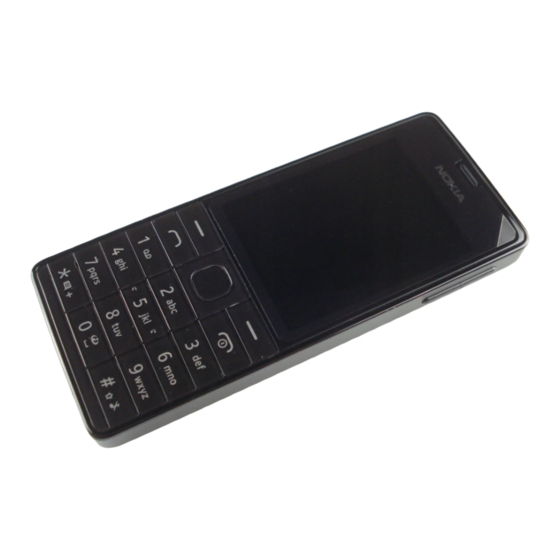
Nokia 515 Dual SIM
(RM-952)
Nokia 515
(RM-953)
Key features
2,4" display (320 x 240) with COrning Gorilla glass
5 Mpix camera with LED flash
Nokia Slam support
MicroSD card support up to 32 GB
Micro-USB connector
Version 1.0
Exploded view
Solder components
Service concept
Disassembly steps
More
Service devices
More
More
©2013 Nokia | Nokia Internal Use only | All Rights Reserved.
Check the repair
policy before
performing any
mechanical repair
on Service Level
1&2!
Assembly hints
More
Product controls and interfaces
More
More
More
Advertisement
Table of Contents


Need help?
Do you have a question about the Nokia 515 RM-953 and is the answer not in the manual?
Questions and answers