Advertisement
INSTALLATION AND OPERATION INSTRUCTIONS
SAVE THESE INSTRUCTIONS
SAVE THSESE INSTRUCTIONS
Caution:
To prevent electric shock disconnect power to heater at main service before wiring or service.
Caution:
Do not obstruct the front of the heater with curtains, furniture, doors, etc. Do not place heaters under
towel racks.Proper operation of the heater requires a free flow intake and exhaust of air.
GENERAL
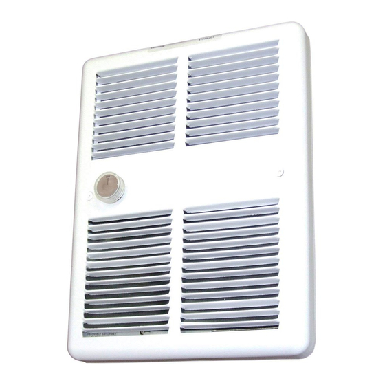
These heaters are designed for 2 X 4 recessed or surface mount installation. The 3200 series heaters may be
wall mounted in a vertical position with top discharge, or horizontal position with right or left discharge. The
minimum clearance for the 3200 series is 12 inches to the adjacent wall and 6 inches minimum from the floor.
These heaters must not be installed without wallbox model no. BOX 30WB.
1.
Position the wall box, maintaining minimum clearances as stated above. Secure to wall stud with nails or
screws. Wall box must be installed with front edge flush with finished wall surface. See figure 1.
2.
Remove knockout in wall box for power source, and install cable clamp.
3.
Insert supply cable through clamp allowing 6-8" for field wiring.
NOTE:
Field wiring must enter the wall box on the left side of the fan end of the heater.
INSTALLATION
INSTRUCTIONS
3200 SERIES
INSTALLATION OF WALL BOX 30WB
FOR NEW CONSTRUCTION
INSTALLATION
INSTRUCTIONS
FORM: 8979
ECO 1-5550
Advertisement
Table of Contents

Summary of Contents for TPI 3200 Series
- Page 1 The minimum clearance for the 3200 series is 12 inches to the adjacent wall and 6 inches minimum from the floor. These heaters must not be installed without wallbox model no. BOX 30WB.
- Page 2 INSTALLATION OF WALL BOX 30WB FOR EXISTING CONSTRUCTION Carefully cut a hole measuring 9 1/4” wide by 12 1/4” long in wall. Wall box BOX4300 must be attached to a wall stud on one edge. Minimum clearances of 12 “ to adjacent wall and 6” to floor must be maintained ces. Attach wall box and secure power cable as in new construction.
- Page 3 WIRING SCHEMATICS MANUAL RESET LIMIT MOTOR ELEMENT CONTROL THERMOSTAT DOUBLE POLE MANUAL RESET LIMIT ELEMENT MOTOR CONTROL L2(N) THERMOSTAT SINGLE POLE MAINTENANCE AND CLEANING The heater should be cleaned at least annually to prevent excess build-up of dirt and lint accumulated under normal operating conditions. In an unusually dirty environment the cleaning should be done more often.


Need help?
Do you have a question about the 3200 Series and is the answer not in the manual?
Questions and answers