
Related Manuals for TPI CF35-C


Summary of Contents for TPI CF35-C
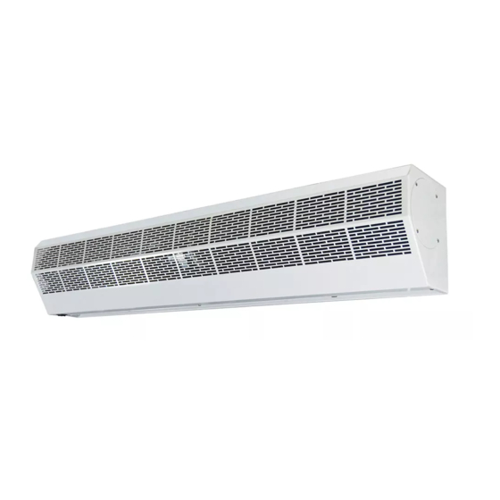
- Page 1 USER’S GUIDE AIR CURTAINS Models: CF35-C, CF47-C, CF59-C Thanks for purchasing this Air Curtain. PLEASE READ AND SAVE THESE INSTRUCTIONS.
-
Page 2: Table Of Contents
WARNING – TO REDUCE THE RISK OF FIRE, ELECTRIC SHOCK, OR INJURY TO PERSONS, OBSERVE THE FOLLOWING: A. Always disconnect, lock and tag power source before installing or servicing. Failure to disconnect power source can result in fire, shock or serious injury. B. -
Page 3: Product Introductions
They can reduce penetration of insects, dust…unconditioned air into a conditioned space by forcing an air stream over the entire entrance to create a comfortable environment for you. 2. INSTALLATION DIMENSIONS UNIT: inch MODEL CF35-C 35.43 11.42 22.05 CF47-C 47.24 1.18... -
Page 4: Installation Cautions
3. INSTALLATION CAUTIONS Must observe the following when installing air curtains: 3.1 Please install the unit on a sturdy 3.2 Please install the unit inside the room. supporting structure to avoid shaking and ensure its security (because the unit running may cause the wall to become loose or shake and make noise). -
Page 5: Installation Instructions
4. INSTALLATION INSTRUCTIONS A. Installing on the concrete wall: 4.1.1 Unscrew the mounting plate and 4.1.2 Determine the mounting location with remove it from the back of the main body. the mounting plate. Fix the bolts in place and pour cement into the bolt holes. 4.1.3 Fix the mounting plate to the wall after 4.1.4 Mount the main body onto the cement setting (use the washers and nuts... -
Page 6: Technical Parameter
100mm. 5. TECHNICAL PARAMETER Max air velocity Air volume Noise level Model Voltage Power (FPM) (CFM) (dB) weight (V~Hz) (Lb) CF35-C 1177 33.1 120~60 2560 1968 CF47-C 1648 1295 43.0 CF59-C 2119 1648 48.5... -
Page 7: Wiring Diagram
6. WIRING DIAGRAM BLUE (YELLOW) ORANGE YELLOW BLACK WHITE GREEN THERMAL CUT-OUT DOUBLE SPEED SWITCH WIRING DIAGRAM 7. OPERATING INSTRUCTIONS 7.1 Connect power to the unit. 7.2 Push the power switch to the left/right to switch on the unit. [L] - Low speed, [H] - High speed. 7.3 Adjust the air deflector to obtain optimum effect.
Need help?
Do you have a question about the CF35-C and is the answer not in the manual?
Questions and answers